

KitchenAid KUDS01VMSS7, KUDS01VMMT7, KUDS01ILWH6, KUDS01FLSS7, KUDI01ILWH6 Installation Guide
...
t
KitchenA;d '>
HOME APPLIANCES
Lavava]immasem
8564554
_r
8564554
TabUe of Contents
Dishwasher Safety ................................. 2
installation Requirements ........................... 3
Tools and parts ................................. 3
Location Requirements .......................... 3
Drain Requirements ............................. 5
Water SuppHy Requirements ...................... 5
EHectricaH Requirements .......................... 5
Installationinstructions............................. 6
Prepare cabinet opening
using existing utility hookups ..................... 6
Prepare cabinet opening
where there are no existing ufiHity hookups .......... 7
Prepare dishwasher ............................. 9
Make electrical connection ...................... 12
Connect to water supply ........................ 13
Connect to drain ............................... 14
Secure dishwasher in cabinet opening ............. 14
Dishwasher Safety
Your safety and the safety of others are very important.
We have provided many important safety messages in this manual and on your appliance. Always read and obey all safety
messages.
This is the safety alert symbol,
This symbol alerts you to potential hazards that can kill or hurt you and others,
Al! safety messages will follow the safety alert symbol and either the word "DANGER" or 'WARNING,"
These words mean:
You can be killed or seriously injured if you don't immediatemy
folmow instructions.
You can be killed or sedousmy injured if you don't follow
instructions.
All safety messages will tell you what the potential hazard is, tell you how to reduce the chance of injury, and tell you what can
happen if the instructions are not followed.
Tip Over Hazard
Do not use dishwasher until compmetemy installed.
Do not push down on open door.
Doing so can resultin serious injury or cuts.
You need to:
®Slowly open dishwasher door while someone grasps the
rear of the dishwasher. Remove shipping materials, drain
hose and lower rack Close dishwasher door until latched.
Observe all governing codes and ordinances.
®Install this dishwasher as specified in these instructions.
o Installation should be performed by a qualified service
technician.The dishwasher must be installed to meet all
electrical and plumbing national and local codes and
ordinances.
Installation Requirements
Location Requirements
TooJs and Parts
Gather the required toois and parts before starting
installation. Read and follow the instructions provided with
any toois Hsted here.
AH installations
Tools needed:
+ piiers
+ PhHHps screwdriver
+ 5/16" and 1/4" nut drivers
or hex sockets
+ measuring tape or ruier
+ 10" adjustabie wrench that
opens to 1-1/8" {2.9 cm)
+ fiat-Made screwdriver
®utility knife
+ 2 twist-on wire connectors
which are the proper size
to connect your househoH
wiring to 16+gauge wiring
in dishwasher
+ small level
+TORX+T15 screwdriver (if
installing custom front
panels)
In addition, for new installations
Tools needed: Parts needed:
+ electric drill with 1/2", 3/4"
and 1-1/2" hole saw bits
+ small tubing cutter
®wire stripper
®1-1/2"+2" screw-type clamp
if connecting to waste+tee
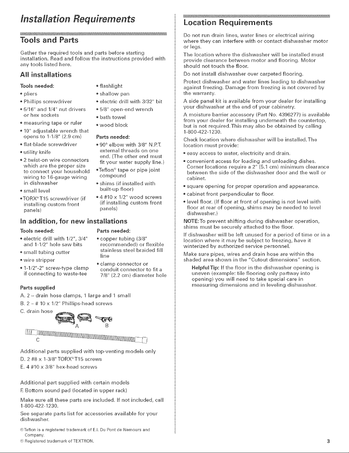
Parts supplied
A. 2 - drain hose clamps, 1 large and 1 small
B. 2 - # 10 x 1/2" Phillips-head screws
C. drain hose
®flashlight
+ shallow pan
+ electric drill with 3/32" bit
+ 5/8" open-end wrench
+ bath towel
+ wood block
Parts needed:
+90° elbow with 3/8" N,RT,
external threads on one
end, (The other end must
fit your water supply line,}
+Teflon x tape or pipe joint
compound
+shims (if installed with
built-up floor)
+4 #10 x 1/2" wood screws
(if installing custom front
panels)
+ copper tubing (3/8"
recommended) or flexible
stainless steel braided fill
line
+ clamp connector or
conduit connector to fit a
7/8" (22 cm) diameter hole
Do not run drain lines, water lines or electrical wiring
where they can interfere with or contact dishwasher motor
or legs.
The location where the dishwasher will be installed must
provide clearance between motor and flooring. Motor
should not touch the floor.
Do not install dishwasher over carpeted flooring.
Protect dishwasher and water lines leading to dishwasher
against freezing. Damage from freezing is not covered by
the warranty.
A side panel kit is available from your dealer for installing
your dishwasher at the end of your cabinetry.
A moisture barrier accessory (Part No. 4396277) is available
from your dealer for installing underneath the countertop,
but is not required.This may also be obtained by calling
1-800-422+1230.
Check location where dishwasher will be installed.The
location must provide:
+ easy access to water, electricity and drain.
+ convenient access for loading and unloading dishes.
Corner locations require a 2" (5.1 cm) minimum clearance
between the side of the dishwasher door and the wall or
cabinet.
+ square opening for proper operation and appearance.
+ cabinet front perpendicular to floor.
+ level floor. (if floor at front of opening is not level with
floor at rear of opening, shims may be needed to level
dishwashery
NOTE:To prevent shifting during dishwasher operation,
shims must be securely attached to the floor.
If dishwasher will be left unused for a period of time or in a
location where it may be subject to freezing, have it
winterized by authorized service personnel.
Make sure pipes, wires and drain hose are within the
shaded area shown in the "Cutout dimensions" section.
HelpfulTip: if the floor in the dishwasher opening is
uneven {example: tile flooring only partway into
opening) you will need to take special care in
measuring dimensions and in leveling dishwasher.
B
C
Additional parts supplied with top-venting models only
D. 2 #8 x l°3/8"TORX+T15 screws
E, 4 #10 x 3/8" hexohead screws
Additional part supplied with certain models
E Bottom sound pad (located in upper rack)
Make sure all these parts are included. If not included, call
1-800+422-1230.
See separate parts list for accessories available for your
dishwasher.
(R;Teflon is a registered trademark of E.I. Du Pont de Nemours and
Company.
{R;Registered trademark of TEXTRON.
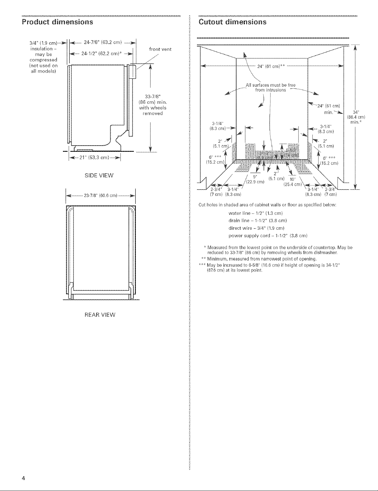
Product dimensions
Cutout dimensions
3/4" (!.9 cm)-a_
insu !ation -
may be
compressed
(not used on
al! models)
24-7/8" (63.2 cm) _1
24-1/2" (62.2 cm) _ _11 _
_- 21" (53.3 cm)--_ I
SIDE VIEW
23-7/8" (60.6 cm)
/
I I front vent
I Ill SS-TJS"
Ill I (s6cm>mh_.
removed
All surfaces must be free
/'_- from intrusions
I ÷1
._ (5.1 cm) 10"
2-3/4" 3-1/4"
(7 cm) (8.3 cm) (8.3 cm) (7 cm)
Cut holes in shaded area of cabinet walls or floor as specified below:
water line - 1/2" (1.3 cm)
drain line- 1-1/2" (3.8 cm)
direct wire - 3/4" (!.9 cm)
power supply cord - 1-1/2" (3.8 cm)
(25.4
34 _'
(86.4 cm)
min.
!
REAR VIEW
Measured from the lowest point on the underside of countertop. May be
reduced to 33-7/8" (86 cm) by removing wheels from dishwasher.
Minimum, measured from narrowest point of opening.
May be increased to 6-5/8" (16.6 cm) if height of opening is 34-1/2"
(876 cm) at its lowest point.

Drain Requirements
EJectricaJ Requirements
o Use the new drain hose suppHbd with your dishwasher.
IftMs is not [ong enough, use a new drain hose with a
maximum [ength of 12 feet (3.7 m) that meets all[
current AHAM/[APMO test standards, is resistant to
heat and detergent, and fits the 1" (2.5 cm) drain
connector of the dishwasher.
o Connect drain hose to waste tee or disposer inlet
above drain trap in house plumbing and 20" (50.8 cm)
minimum above the floor, it is recommended that the
drain hose either be looped up and securely fastened
to the underside of the counter, or be connected to an
air gap.
air gap
o Use an air gap if the drain hose is connected to house
plumbing lower than 20" (50.8 cm} above subfloor or
floor.
o Use 1/2" minimum I.D. drain line fittings.
Water SuppJy Requirements
_A hot water line with 20-120 psi (138-862 kPa) water
pressure.
o 120°F (49°C) water at dishwasher.
o 3/8" O.D. copper tubing with compression fitting or
flexible stainless steel braided fill line (1/2" minimum
plastic tubing is not recommended).
o A 90 ° elbow with 3/8" N.RT. external pipe threads on
one end.
Do not solder within 6" (15.2 cm) from water inlet valve.
Contact a qualified electrician.
Assure that the electrical installation is adequate and in
conformance with aii national and local codes and
ordinances.
You must have:
o 120-volt, 60 Hz, AC-only, 15 or 20 amp, fused electrical
suppl%
®Copper wire only.
We recommend:
o A timeodelay fuse or circuit breaker.
o A separate circuit,
ff direct wiring dishwasher:
Use flexible, armored or nonometallic sheathed, copper
wire with grounding wire that meets the wiring
requirements for your home and local codes and
ordinances.
Use strain relief method provided with house wiring
junction box or install a U.L.-listed/CSAocertified clamp
connector to the house wiring junction box. if using
conduit, use a U.L.-listed/CSA-certified conduit connector.
_fconnecting dishwasher with a power supply cord:
Use Power Supply Cord Kit (Part No. 4317824} marked for
use with dishwashers. Kit contents include:
-Volex, inc., UL listed 16 gauge 3 wire power supply
cord with 3 prong grounded plug.
- Neer C-500 7/8 inch strain relief.
- 3 wire connectors.
- Part No. 302797 grommet
Follow the kit instructions for installing the power
supply cord.
o Power supply cord must plug into a mating three prong,
grounded outlet, located in the cabinet next to the
dishwasher opening. Outlet must meet all local codes and
ordinances.
/nstM/ation instructions
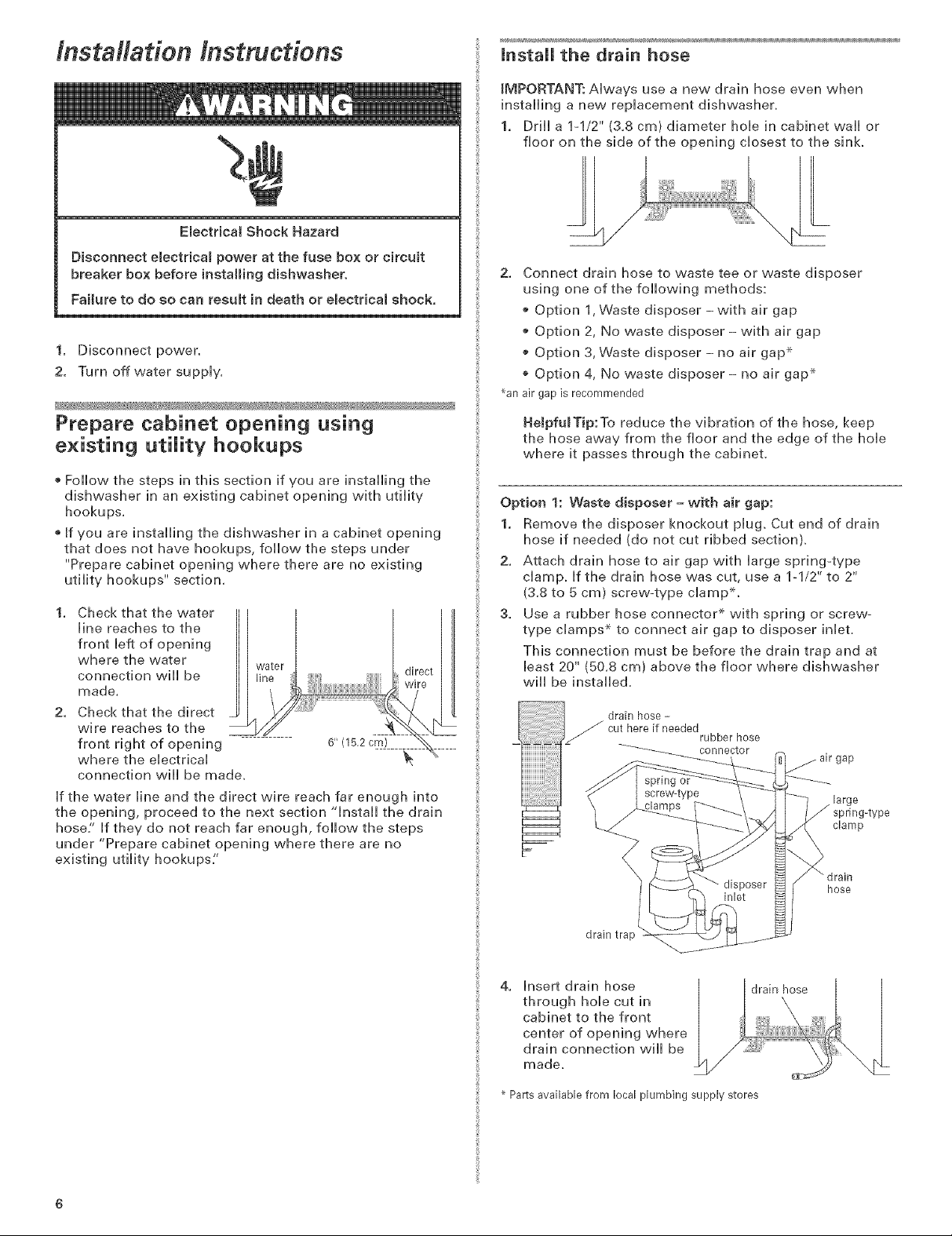
EBectricat Shock Hazard
Disconnect e{ectricam power at the fuse box or circuit
breaker box before installing dishwasher.
Failure to do so can result }n death or emectr}ca{ shock,
1. Disconnect power.
2. Turn off water suppiy.
mnstaH the drain hose
IMPORTANT: Always use a new drain hose even when
installing a new replacement dishwasher,
1. Drill a 1-1/2" (3,8 cm) diameter hob in cabinet wall or
floor on the side of the opening closest to the sink
2. Connect drain hose to waste tee or waste disposer
using one of the following methods:
o Option 1, Waste disposer-with air gap
o Option 2, No waste disposer- with air gap
o Option 3, Waste disposer - no air gap .×
Option 4, No waste disposer - no air gap _
_anair gap is recommended
Prepare cabinet opening using
existing utility hookups
Follow the steps in this section if you are installing the
dishwasher in an existing cabinet opening with utility
hookups.
®If you are installing the dishwasher in a cabinet opening
that does not have hookups, follow the steps under
"Prepare cabinet opening where there are no existing
utility hookups" section.
1. Check that the water
line reaches to the
front left of opening
where the water
connection will be
made.
2. Check that the direct _
wire reaches to the
front right of opening 6" (15.2 cm)
where the electrical
connection will be made.
If the water line and the direct wire reach far enough into
the opening, proceed to the next section "install the drain
hose/' If they do not reach far enough, follow the steps
under "Prepare cabinet opening where there are no
existing utility hookups:'
HeJpfulTip:To reduce the vibration of the hose, keep
the hose away from the floor and the edge of the hole
where it passes through the cabinet.
Option 1: Waste disposer -with air gap:
1. Remove the disposer knockout plug. Cut end of drain
hose if needed (do not cut ribbed section).
2. Attach drain hose to air gap with large spring-type
clamp. If the drain hose was cut, use a 1-1/2" to 2"
(3.8 to 5 cm) screw-type clampX.
3. Use a rubber hose connector _ with spring or screw-
type clamps _ to connect air gap to disposer inlet.
This connection must be before the drain trap and at
bast 20" (50.8 cm) above the floor where dishwasher
will be installed,
drain hose -
cut here if needed
rubber hose
ector
gap
large
J spring-type
clamp
_ drain
hose
drain trap
4. Insert drain hose
through hole cut in
cabinet to the front
center of opening where
drain connection will be
made,
Parts available from local plumbing supply stores
drain hose

Option 2: No waste disposer - with air gap:
1. Cut end of drain hose if needed (do not cut ribbed
section).
2. Attach drain hose to air gap with large spring-type
damp. if the drain hose was cut, use a 1-1/2" to 2"
(&8 to 5 cm) screw-type damp ×,
3. Use a rubber hose connector _ with spring or screw-
type damps .×.to connect air gap to waste tee_
This connection must be before the drain trap and at
least 20" (50.8 cm) above the floor where dishwasher
will be installed_
drain hose-
cut here if needed
rubber hose
connector
large
spring4ype
waste
drain trap hose
tee drain
Option 4: No waste disposer - no air gap:
1. Cut end of drain hose if needed (do not cut ribbed
section),
2. Attach drain hose to waste tee with lq/2" to 2"
(3,8 to 5 cm) screw-type clampX,
This connection must be before the drain trap and at
bast 20" (50,8 cm) above the floor where dishwasher
will be installed, it is recommended that the drain hose
be looped up and securely fastened to the underside of
the counter,
4. insert drain hose |
through hob cut in
cabinet to the front
center of opening where
drain connection will be /
made.
Parts available from local plumbing supply stores
drain hose
Option 3: Waste disposer - no air gap:
1. Remove the disposer knockout plug. Do not cut end of
drain hose.
2. Attach drain hose to disposer inlet with large spring_
type damp.
This connection must be before the drain trap and at
least 20" (50.8 cm) above the floor where dishwasher
will be installed, it is recommended that the drain hose
be looped up and securely fastened to the underside of
the counter.
large spring-type
clamp
drain hose
disposer
inlet
drain trap
3. insert drain hose |
through hole cut in
cabinet to the front
center of opening where
drain connection will be
made.
drain hose
3. Insert drain hose
through hole cut in
cabinet to the front
center of opening where
drain connection will be
made.
Parts available from local plumbing supply stores
drain hose
Prepare cabinet opening where there
are no existing utility hookups
Electrical connection
Option1: Direct wire method:
HeJpfu_Tip: Wiring the dishwasher wiii be easier if you
route wire into the cabinet opening from the right side.
1. Drill a 3/4" (1.9 cm) optional preferred
hob in right-hand locations locations
cabinet side, rear or
floor. Preferred and
optional locations are
shown.
2. Wood cabinet: Sand
hob until smooth.
Metal cabinet: Cover
hob with grommet, not provided.
3,
Run wire into house wiring junction box.
4.
Install a U.L.qisted/CSA-certified clamp connector
(strain relief) for flexible-type wire. If installing conduit,
attach a U.L.qisted/CSA-certified conduit connector to
the junction box.
5,
Run other end of wire
through cabinet hole.
Cable must extend to the
right front of cabinet
opening.
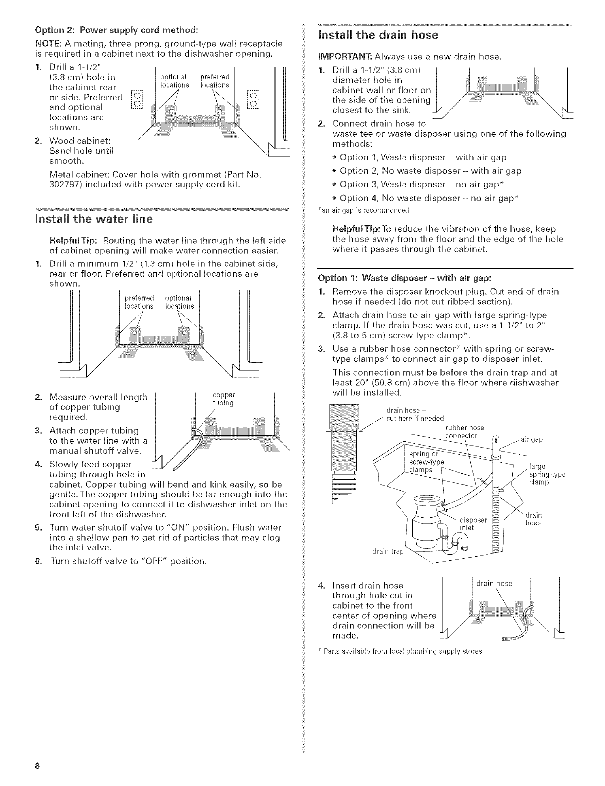
Option2: Powersupplycordmethod:
NOTE:Amating,threeprong,ground-typewallreceptacle
isrequiredinacabinetnexttothedishwasheropening.
1. Drilla1ol/2"
(3.8cm)holein optionalpreferred
thecabinetrear locationslocations
orside,Preferred[ii_i
andoptional ......
locationsare
shown.
2. VVoodcabinet:
Sandholeuntil
smooth.
Metal cabinet: Cover hole with grommet (Part No.
302797) included with power supply cord kit.
mnstall the water line
NeJpfuJTip: Routing the water line through the left side
of cabinet opening will make water connection easier.
Drill a minimum 1/2" {1.3 cm) hole in the cabinet side,
rear or floor. Preferred and optional locations are
shown.
preferred
locations
2. Measure overall length
of copper tubing
required.
3. Attach copper tubing
to the water line with a
manual shutoff valve.
4. Slowly feed copper
tubing through hole in
cabinet. Copper tubing will bend and kink easily, so be
gentle.The copper tubing should be far enough into the
cabinet opening to connect it to dishwasher inlet on the
front left of the dishwasher.
5. Turn water shutoff valve to "ON" position. Flush water
into a shallow pan to get rid of particles that may clog
the inlet valve.
6. Turn shutoff valve to "OFF" position.
optional
locations
copper
tubing
mnstaH the drain hose
IMPORTANT: Always use a new drain hose.
1. Drill a 1-1/2" (3.8 cm)
diameter hole in
cabinet wall or floor on
the side of the opening
closest to the sink.
2. Connect drain hose to
waste tee or waste disposer using one of the following
methods:
o Option 1,Waste disposer -with air gap
o Option 2, No waste disposer- with air gap
o Option 3, Waste disposer- no air gap _
Option 4, No waste disposer - no air gap _
_anair gap is recommended
HeJpfulTip:To reduce the vibration of the hose, keep
the hose away from the floor and the edge of the hole
where it passes through the cabinet.
Option 1: Waste disposer = with air gap:
1. Remove the disposer knockout plug. Cut end of drain
hose if needed (do not cut ribbed section).
2. Attach drain hose to air gap with large spring-type
clamp. If the drain hose was cut, use a 1-1/2" to 2"
(3.8 to 5 cm) screw-type clampS.
3. Use a rubber hose connector _ with spring or screw-
type clamps _ to connect air gap to disposer inlet.
This connection must be before the drain trap and at
least 20" (50.8 cm) above the floor where dishwasher
will be installed.
drain hose -
cut here if needed
rubber hose
connector
drain trap
gap
large
J spring-type
clamp
hose
4. Insert drain hose
through hole cut in
cabinet to the front
center of opening where
drain connection will be
made.
Parts available from local plumbing supply stores
drain hose

Option 2: No waste disposer - with air gap:
1. Cut end of drain hose if needed (do not cut ribbed
section).
2. Attach drain hose to air gap with Harge spring-type
champ. If the drain hose was cut, use a 1-1/2" to 2"
(&8 to 5 cm) screw-type cHamp x,
3. Use a rubber hose connector _ with spring or screw-
type champs .×.to connect air gap to waste tee_
This connection must be before the drain trap and at
Heast20" (50.8 cm) above the floor where dishwasher
wHHbe instaHHe&
cuthereif needed
rubber hose
connector
Option 4: No waste disposer - no air gap:
1. Cut end of drain hose if needed (do not cut ribbed
section),
2. Attach drain hose to waste tee with lq/2" to 2"
(3,8 to 5 cm) screw-type clampX,
This connection must be before the drain trap and at
least 20" (50,8 cm) above the floor where dishwasher
will be installed, it is recommended that the drain hose
be looped up and securely fastened to the underside of
the counter,
. drain hose-
drain trap hose
springor
large
spring4ype
waste
tee drain
4. hsert drain hose
through hoHe cut in
cabinet to the front
center of opening where
drain connection wHHbe
ZL drain hose
made,
Parts available from local plumbing supply stores
Option 3: Waste disposer = no air gap:
1. Remove the disposer knockout pHug. Do not cut end of
drain hose.
2, Attach drain hose to disposer inlet with large spring_
type clamp,
This connection must be before the drain trap and at
least 20" (50,8 cm) above the floor where dishwasher
will be installed, It is recommended that the drain hose
be looped up and securely fastened to the underside of
the counter,
large spring-type
clamp
drain hose
disposer
inlet
3. Insert drain hose
through hole cut in
cabinet to the front
center of opening where
drain connection will be
made_
Parts available from local plumbing supply stores
l/if drain hose
Prepare dishwasher
Tip Over Hazard
Do not use dishwasher until completemy installed.
Do not push down on open door,
Doing so can result in serious iniury or cuts.
drain trap
3. Insert drain hose
through hole cut in
cabinet to the front
center of opening where
drain connection will be
made,
drain hose
Put corner posts from packaging behind dishwasher,
Grasp sides of dishwasher door frame and put
dishwasher on its back, resting on top of the corner
posts,

2. Remove two screws attaching access panei and bwer
panei to dishwasher using a 1/4" hex socket, nut driver
or PMHips screwdriver.
3. Remove paneis and set paneis aside on a protective
surface.
4. Check that grounding chip is attached to the bwer
panel,
8. Measure height of cabinet opening
from underside of countertop to
floor where dishwasher will be
installed (you need the lowest
point). Check chart for that height
opening. Put wheels in the required
position.
Minimum Wheel
cutout height position front leg
34" (86.4 cm) 1 10
34-1/4" (87 cm) 2 5
wheel
34-I/2" (87.6 cm) 3 0
Number of
turns on
lower
panel
clip
water inlet valve
5. ApplyTeflon :" tape or pipe
joint compound to 90 ° elbow
fitting and connect fitting to
water inlet valve.
& Tighten elbow until snug, and
be sure that it faces to the
rear.
7. Remove terminal box cover. Puii appliance wires
through hole in terminal box. Do not untie the knot in
the wires.
- if you are direct wiring: install a U,h-listed/CSAo
certified damp connector to the terminal box, if using
conduit, use a U,L,olisted/CSAocertified conduit
connector,
- if you are installing a power supply cord kit, do so
now, following kit instructions,
8,
Turn both front leveler legs to the same
height.
If the minimum cutout height is less than
34" (86.4 cm), the rear wheels can be
removed for additional clearance.This will
allow the dishwasher to fit into a 33-7/8"
(86 cm) high cutout, but the dishwasher
wiii be more difficult to move into
position, if the wheels are removed,
protect the floor when moving the dishwashen
If you have built-up floors
1. Measure height of opening
/ countertop
from underside of
countertop to built-up
floor, if the height is at
bast 33-3/4" (85.7 cm), the
dishwasher will fit into the
opening without
modification to the
countertop or flooring.
2. Put wheels in position 1
shim &) t°?
and turn the front leveler
legs up all the vva%
3,
Add shims as needed in the area shown to bring
dishwasher up to proper height.
NOTE: Shims must be securely attached to floor to
prevent their movement when the dishwasher is
operated.
frontleg
33-3/4"
(85.7 cm)
min.
dishwasher
wires --...
\
cable clamp connector
HeJpfuJTip: Put cardboard under dishwasher until it is
installed in cabinet opening.The cardboard will help
protect floor covering during installation.
lO
2"
(5,1 cm)
shim shim
2-3/4" 6"
(7.0cm) (15,2cm) (ZOcm)

JnstaR the door handle {on some modeHs)
IMPORTANT: Do not scratch the front paneH during this
procedure,
1. Remove the Architect TM Series handHe, pHasfic washers
and two screws from handHe package,
2. Attach the handHe to the factory-suppHied full front paneH
as shown,
5. Gently set panel aside,
NOTE: Some models have 4 screws per side.
screws
film that is JfJ'--
not to be
removed
Pro Line "_Series
1. Remove the Pro Line TM Series handHe and two screws
from handHe package,
2. Make sure phsfic spacers are sfiU attached to the door,
3. Attach the handHe to the factory-suppHied full front paneH
as shown,
Install door panel {on some models)
screws door
panel do not remove screw.
6. Lay the factory-supplied full front panel face down on a
protective non-scratching surface.
7. Place the inner panel on the back of the full front panel
as shown and attach, using the four #10-16 x 3/8" screws
in the literature package.
4 screws
?
/
full front panel
inner door panel _ top of panel
8. Attacl_ tl_e factory-supplied full front panel, inner panel,
and handle assembly to the door,
9. Reinstall the two uppermost screws into the inner panel,
do not tighten completely, This will hold the full front
panel in place on the door frame,
Top vented models
NOTE: Features on your
dishwasher may differ
from model shown. vent
Option 1:
ForTop vented models with a factory-supplied stainless or
painted full front panel:
1. Remove the carton containing the factory-supplied full
front panel.
2. Remove the handle package from the front of the
shipping base.
3. Remove the inner panel from the door.
4. With aTORX _screwdriver, remove three screws from
both sides of the door. Hold the inner panel up while
removing the screws.
2 screws ,
10. hstall the two #8-18 x 1-3/8" screws from the literature
package in the top corners of the door.
11. Align the top edge of the full front panel with the top
edge of the console and secure corner screws.
12. Tighten the two screws installed in Step 9.
13. Reinstall and tighten the remaining screws in the inner
panel.
2screws i
align top edges
11
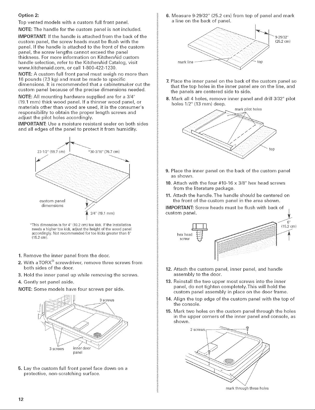
Option 2:
Top vented modeHs with a custom full front panel
NOTE: The handHe for the custom paneH is not incHuded.
IMPORTANT: Hfthe handHe is attached from the back of the
custom panel the screw heads must be flush with the
panel Hfthe handHe is attached to the front of the custom
paneH, the screw Hengths cannot exceed the paneH
thickness. For more information on KitchenAid custom
handHe seHecfion, refer to the KitchenAid CataHog, visit
www.Mtchenaid.com, or call 1-800-422-1230_
NOTE: A custom full front paneH must weigh no more than
16 pounds (7_3 kg) and must be made to specific
dimensions. Htis recommended that a cabinetmaker cut the
custom panel because of the precise dimensions needed.
NOTE: All mounting hardware supplied are for a 3/4"
(19.1 ram) thick wood panel. If a thinner wood panel, or
materials other than wood are used, it is the consumer's
responsibility to obtain the proper length screws and
adjust the pilot holes accordingl%
IMPORTANT: Use a moisture resistant sealer on both sides
and all edges of the panel to protect it from humidity.
23-1/2" (59,7cm) m _30-3/16"(76,7cm)
6. Measure 9-29/32" (25.2 cm) from top of panel and mark
a line on the back of panel.
(25,2 cm)
mark line
7. Place the inner panel on the back of the custom panel so
that the top holes in the inner panel are on the line, and
the panels are centered side to side.
8. Mark all 4 holes, remove inner panel and drill 3/32" pilot
holes 1/2" (13 ram) deep.
mark pilot holes
custom pane!
dimensions
_This dimension is for 4" (10.2 cm) toe kick. If the installation
needs a higher toe kick, adiust the height of the wood panel
accordingly, Not recommended for toe kicks greater than 6"
(15,2 cm).
/
3/4" (19.1 ram)
1. Remove the inner panel from the door,
2. With aTORX <_)screwdriver, remove three screws from
both sides of the door,
3. Hold the inner panel up while removing the screws,
4. Gently set panel aside.
NOTE: Some models have four screws per side,
3 screws
9. Place the inner panel on the back of the custom panel
as shovvn_
10. Attach with the four #10-16 x 3/8" hex head screws
from the literature package.
11. Attach the handle.The handle should be centered on
the front of the custom panel in the area shown.
_MPORTANT: Screw heads must be flush with back of
custom panel.
(15,2 cm)
12.
Attach the custom panel, inner panel, and handle
assembly to the door.
13.
Reinstall the two upper most screws into the inner
panel, do not tighten completely.This will hold the
custom panel assembly in place on the door frame.
14.
Align the top edge of the custom panel with the top of
the console.
15.
Mark two holes on the custom panel through the holes
in the upper corners of the inner panel and console, as
shown,
3 screws inner door
panel
5. Lay the custom full front panel face down on a
protective, non-scratching surface.
12
mark through these holes
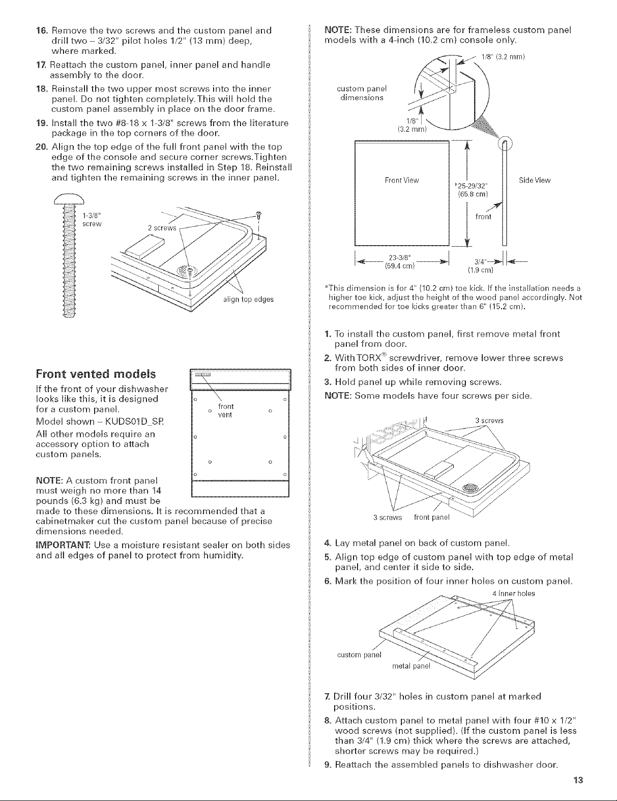
16.Removethetwoscrewsandthecustompaneiand
drHitwo- 3/32"pilothobs1/2"(13ram)deep,
wheremarked.
17. Reattach the custom panei, inner panei and handie
assemMy to the door,
18. Reinstall the two upper most screws into the inner
panel Do not tighten compbteiy, This wHi hoH the
custom panei assemMy in piace on the door frame.
19. Install the two #8-18 x 1-3/8" screws from the iiterature
package in the top corners of the door,
20. Aiign the top edge of the full front panei with the top
edge of the consoie and secure corner screws,Tighten
the two remaining screws installed in Step 18, Reinstall
and tighten the remaining screws in the inner panel
2 screws
align top edges
NOTE: These dimensions are for frameless custom panel
models with a 4-inch (10,2 cm) console only,
custom panel
dimensions
Front View
If-- 23_3J8,, 3J4÷1÷
(59.4cm)
*This dimension is for 4" (10.2 cm) toe kick. If the installation needs a
higher toe kick, adjust the height of the wood panel accordingly. Not
recommended for toe kicks greater than 6" (15.2 cm).
_25-29/32"
(65,8 cm)
fro/
(1.9cm)
Side V[ew
Front vented models
If the front of your dishwasher
looks like this, it is designed
for a custom panel,
Model shown - KUDSO1D SR
All other models require an
accessory option to attach
custom panels,
NOTE: A custom front panel
must weigh no more than 14
pounds (&3 kg} and must be
made to these dimensions, It is recommended that a
cabinetmaker cut the custom panel because of precise
dimensions needed,
IMPORTANT: Use a moisture resistant sealer on both sides
and all edges of panel to protect from humidity.
o \
front
o o
vent
1. To install the custom panel, first remove metal front
panel from door,
2. WithTORX '_:screwdriver, remove lower three screws
from both sides of inner door,
3. Hold panel up while removing screws,
NOTE: Some models have four screws per side,
3 SCrews
3 screws front panel
4. Lay metal panel on back of custom panel,
5. Align top edge of custom panel with top edge of metal
panel, and center it side to side,
6. Mark the position of four inner holes on custom panel,
4 inner holes
custom panel
metal panel
7. Drill four 3/32" holes in custom panel at marked
positions,
8. Attach custom panel to metal panel with four #10 x 1/2"
wood screws (not supplied), (if the custom panel is less
than 3/4" (1,9 cm) thick where the screws are attached,
shorter screws may be required,)
9. Reattach the assembled panels to dishwasher door,
13

Choose attachment option
Using two or more peopHe, stand the dishwasher up.
Option 1: Countertop attachment
The dishwasher must be
secured to the cabinet, There
are two brackets on top of the
dishwasher that can be
attached to the countertop if it
is wood, laminate or other
similar surfaces. If this is not
possible, the brackets may be
moved to the sides of the _
dishwasher.
NOTE: Do not attach the
dishwasher, this will be done
Hater.
Option 2: Dishwasher side attachment
(for marble, granite or other hard surface
countertop)
1. To remove the brackets from the top, flatten tab at back
of brackets with pliers, and pull the brackets out of the
slots,
/
tabs
brackets
front vent
model shown
5. Push bracket into slot on the side of dishwasher, and
bend tab in towards the side of the dishwasher so that
it keeps the bracket in place.
NOTE: Do not attach the dishwasher, this will be done
later.
(
Move dishwasher into cabinet opening
1.
Grasp the sides of the dishwasher
at the edges of the door panel.
2.
Tilt dishwasher backwards on
wheels and move dishwasher close
to cabinet opening. Do not push on
the front of the panel or on the
console--they may dent,
3.
If dishwasher has a power supply
cord, insert power supply cord into hole cut into
cabinet.
If using direct wire, check that it is on the right front
side of opening.
4.
Check that water line is on the left side of opening and
drain hose is near the center of the hole in the cabinet.
5.
Slowly move dishwasher completely into cabinet
opening. Do not kink or pinch copper tubing, drain
hose, power supply cord or direct wire between
dishwasher and cabinet.
He_pfulTip: Once the dishwasher is in position, you
may have to support the front of the dishwasher by
raising, lowering or shimming front feet.
6.
Remove cardboard from under dishwasher.
NOTE: It is all right if dishwasher fits tightly into cabinet
opening. Do not remove insulation blanket --the blanket
reduces the sound level.
2. Break offthe end of the bracket along the scored line.
score
line
3. Open dishwasher door and place towel over pump
assembly and spray arm of dishwasher.This will
prevent screws from falling into pump area when
securing dishwasher to cabinet.
4. Push the plastic buttons out of the side of the tub.
NOTE: Save the buttons to cover the holes after
dishwasher is installed.
14

Check door spring tension
1. With another person holding the dishwasher to prevent
it from tipping, open and close the door a few times. If
the door closes or falls open under its own weight, the
door tension will need to be adjusted.
2. To adjust the door spring tension, unhook the spring
from the rear leg of dishwasher.
3. With a 5/16" nut driver or hex socket, remove the screw
from the tensioner.
4. The screw can be put into one of three holes D, F_Jl,D
in front leg of dishwasher. If the door closes by itself,
move the tensioner to a higher number hole and
replace screw. When door is unlatched, if it opens by
itself, move tensioner to a lower numbered hole and
replace screw.
5. Re-attach door spring to rear leg.Tensioners on both
sides of dishwasher should be secured at same holes.
spring
4. Repeat for other side of dishwasher,
NOTE: Shims must be securely attached to floor to prevent
their movement when the dishwasher is operated,
5. Place level against top front
opening of tub, Check that
dishwasher is level from side to
side, If dishwasher is not level,
adjust front legs up or down until
dishwasher is level,
Make EJectricaJ Conrlection
Check "Electrical requirements" section,
You need to:
®have the correct electrical supply and recommended
grounding method,
if you are:
direct wiring, use Option 1
o using a power supply cord, use Option 2
Option 1: Direct wire method
1. Route direct wire so that it does not touch dishwasher
motor or lower part of dishwasher tub.
2. Pull direct wire through hole in terminal box.
screw
LeveU the dishwasher
Align front of dishwasher door panel with cabinet
doors,You may need to adjust alignment to be even
with your cabinets,
HelpfulTip: Prop up one side of frame to hold
dishwasher up off floor when adjusting front legs,
2. Check that leveling legs are firmly against the floor,
3. Close and latch the door, and place level against the
front panel, Check that dishwasher is plumb, If needed,
adjust leveling leg or add shims under rear wheel until
dishwasher is plumb,
He_pfu_ Tip:
o Select the proper size twist-on
connectors to connect your household _x_
wiring to 16-gauge dishwasher wiring,
o Insert wire ends into twist-on
connector, Do not pre-twist bare wire,
oTwist connector,
o Gently tug on wires to be sure both
are secured_
3. Connect the wires as follows using twistoon connectors
sized to connect direct wire to 16-gauge dishwasher
wire:
Powersupplywire: Terminalboxwire:
white--white
black--black
groundwire_gr0und connector
%/
J
15

ElectficamShockHazard
Option 2: Power supply cord method
Emectricallygrounddishwasher.
Connectgroundwiretogreengroundconnectorin
terminambox.
Donotuseane×tension cord,
Failure to follow these instructions can resumt in death,
fire, or electrical shock.
4. Form bare ground wire into a U-shaped hook, Wrap
ground wire hook cbckwbe around ground connector
and under the washer.
5. Secureiy tighten ground connector, Do not untie knot in
the wires,
groundwire washer
ground wire
6. Tighten clamp connector or conduit connector screws,
screws
ground
connector
/
Emectrical Shock Hazard
Plug into a grounded 3 prong outmet.
Do not remove ground prong.
Do not use an adapter.
Do not use an extension cord.
Faimureto follow these instructions can result in death,
fire, or emectrica_ shock.
1. Hug into a grounded 3 prong outlet,
2. Check that power supply cord does not touch
dishwasher motor or lower part of dishwasher tub,
Connect to water supph!
He_pfu_ Tip:
Compression fittings:
a. Slide nut onto copper tubing about 1" (2.5 cm).
b. Slide ferrule onto the tubing. Do not position ferrule
on the end of the tubing.
c. Put the tubing into the elbow as far as it will go.
d. Slide the nut and ferrule forward and start the nut
onto the elbow threads. Be gentle when handling
and positioning the copper tubing, it bends and kinks
easily.
nut
7. Reinstall terminal box cover with wires inside terminal
box,
The cover must be outside the box on the Heftside,
8. Make sure no wires are pinched by cover,
16
elbow
1. To prevent vibration during operation, route the water
supply line so that it does not touch the dishwasher
base, frame or motor.
2. With copper tubing pushed into compression fitting as
far as it will go, use a wrench and tighten compression
fitting nut to elbow on water inlet valve.
3. Place paper towel under elbow, Turn on water supply
and check for leaks,

Connect to drain
1. To heHp minimize
vibration, route drain
hose to avoid contact
with motor, door springs,
water Hine, cabinet,
flooring or the edge of
the hoHe where it passes
through the cabinet.
2. Do not remove drain
Hoop from side of
dishwasher_
3. Hace pan under end of drain hose. Pan wHHcollect any
water in drain hose.
4. Remove pHug and paper from drain connector.
NOTE: Cutting the zip tie hoHding the end of drain hose
in pHace may make maneuvering the drain hose easier
during installation.
zip tie
hose
5. Hace the smaller drain hose
champ onto the small end of the
drain hose.
/J clamp
Secure dishwasher in cabinet opening
Tip Over Hazard
Do not use dishwasher antim completely installed.
Do not push down on open door.
Doing so can result in serious iniury or cuts.
If you have not already done so, open dishwasher door
and place towel over pump assembly and spray arm of
dishwasher.This will prevent screws from falling into
pump area when securing dishwasher to countertop.
2,
Check that dishwasher is still level and centered side to
side in the opening.
3.
Secure dishwasher to countertop or sides of cabinet
with two, #10 x 1/2" Phillips-head screws.The
dishwasher must be secured to keep it from tipping
when door is opened. Do not drop screws into bottom
of dishwasher.
OR
6. Push the drain hose into the connector up to the stop
on the drain hose,
connector stop
7. Use pliers to open clamp and slide clamp onto
connector between stops on connector as shown,
hose clamp
,j
stops
d
4. Open door about 3 inches (7.6 cm) and check that space
between inner door and tub is equal on both sides. If
spacing is not equal, loosen bracket screws and shift
tub.Tighten bracket screws.
5. Check that top of door does not contact screws,
brackets, or countertop. If it does, dishwasher must be
lowered and reoleveled.
6. If securing to sides of cabinet, replace the plastic
buttons.
7. Remove towel from dishwasher,
8. Reinstall the lower dishrack
17
 Loading...