

KitchenAid KUDD03DT User Manual
8546448
®
HOME APPLIANCES
Installation Instructions
8546448
Drawer Dishwasher
528138/8546448
Table of Contents
Drawer Dishwasher Safety. . . . . . . . . . . . . . . . . . . . . . . . . . . . 2
Installation Requirements. . . . . . . . . . . . . . . . . . . . . . . . . . . . . 3
Tools and Parts . . . . . . . . . . . . . . . . . . . . . . . . . . . . . . . . . . . 3
Location Requirements . . . . . . . . . . . . . . . . . . . . . . . . . . . . . 3
Water Supply Requirements . . . . . . . . . . . . . . . . . . . . . . . . . 4
Electrical Requirements . . . . . . . . . . . . . . . . . . . . . . . . . . . . . 4
Installation Instructions . . . . . . . . . . . . . . . . . . . . . . . . . . . . . . 5
Prepare Cabinet Opening . . . . . . . . . . . . . . . . . . . . . . . . . . . 5
Electrical Connection . . . . . . . . . . . . . . . . . . . . . . . . . . . . . . . 5
If Installing Flexible Trim Pieces. . . . . . . . . . . . . . . . . . . . . . . 8
Install Dishwasher . . . . . . . . . . . . . . . . . . . . . . . . . . . . . . . . . 8
Install Drain Hose . . . . . . . . . . . . . . . . . . . . . . . . . . . . . . . . . 10
Connect to Water Supply . . . . . . . . . . . . . . . . . . . . . . . . . . 11
Install Drawer Front Panels and Toe Panel . . . . . . . . . . . . . 11
Complete Installation . . . . . . . . . . . . . . . . . . . . . . . . . . . . . . 15
DRAWER DISHWASHER SAFETY
Your safety and the safety of others are very important.
We have provided many important safety messages in this manual and on your appliance. Always read and obey all safety
messages.
This is the safety alert symbol.
This symbol alerts you to potential hazards that can kill or hurt you and others.
All safety messages will follow the safety alert symbol and either the word “DANGER” or “WARNING.”
These words mean:
You can be killed or seriously injured if you don't immediately
DANGER
WARNING
All safety messages will tell you what the potential hazard is, tell you how to reduce the chance of injury, and tell you what can
happen if the instructions are not followed.
follow instructions.
can be killed or seriously injured if you don't
You
instructions.
follow
2
INSTALLATION REQUIREMENTS
Tools and Parts
Gather the required tools and parts before starting
installation. Read and follow the instructions provided with
any tools listed here.
Tools needed:
■ utility knife
■ needle-nose pliers
■ tape measure
■ flat-bladed screwdriver
■ #2 Phillips screwdriver
■ side cutting pliers
■ pencil
■ sandpaper
■ level
■ wood cutting board
■ adjustable wrench that
opens to 1-1/8" (29 mm)
Parts supplied:
Located in bottom drawer:
■ 2 flexible trim pieces (for sides)
■ 1 flexible trim piece (for top)
■ edge protection
■ hose clamp, hose type
■ washer
■ 2 installation brackets (top)
■ drain hose support
■ drain hose connector
■ 2 hose clamps, wire type
■ 24 #8 Phillips head wood screws
■ toe panel
■ custom toe panel mounting bracket
■ moisture protection tape
■ 7 mm socket wrench
■ 5 mm socket wrench
■ 5 mm open end or box end
wrench
■ electric or hand drill
■ 1-1/2" hole saw
■ valve (sized to fit hot water
supply line) with 3/8" male
compression fitting
■ protective floor covering
Location Requirements
IMPORTANT: Observe all governing codes and ordinances.
Failure to meet codes and ordinances could lead to fire or
electrical shock.
Proper installation is your responsibility:
■ Contact a qualified installer to ensure that the dishwasher is
installed to meet all electrical and plumbing national and local
codes and ordinances.
■ Install the dishwasher as specified in these instructions.
■ Have everything you need to properly install dishwasher.
■ Protect dishwasher and water lines leading to dishwasher
against freezing. Damage from freezing is not covered by the
warranty.
■ This dishwasher is manufactured for indoor use only.
■ Install and level dishwasher on a floor that will hold the weight,
and in an area suitable for its size and use.
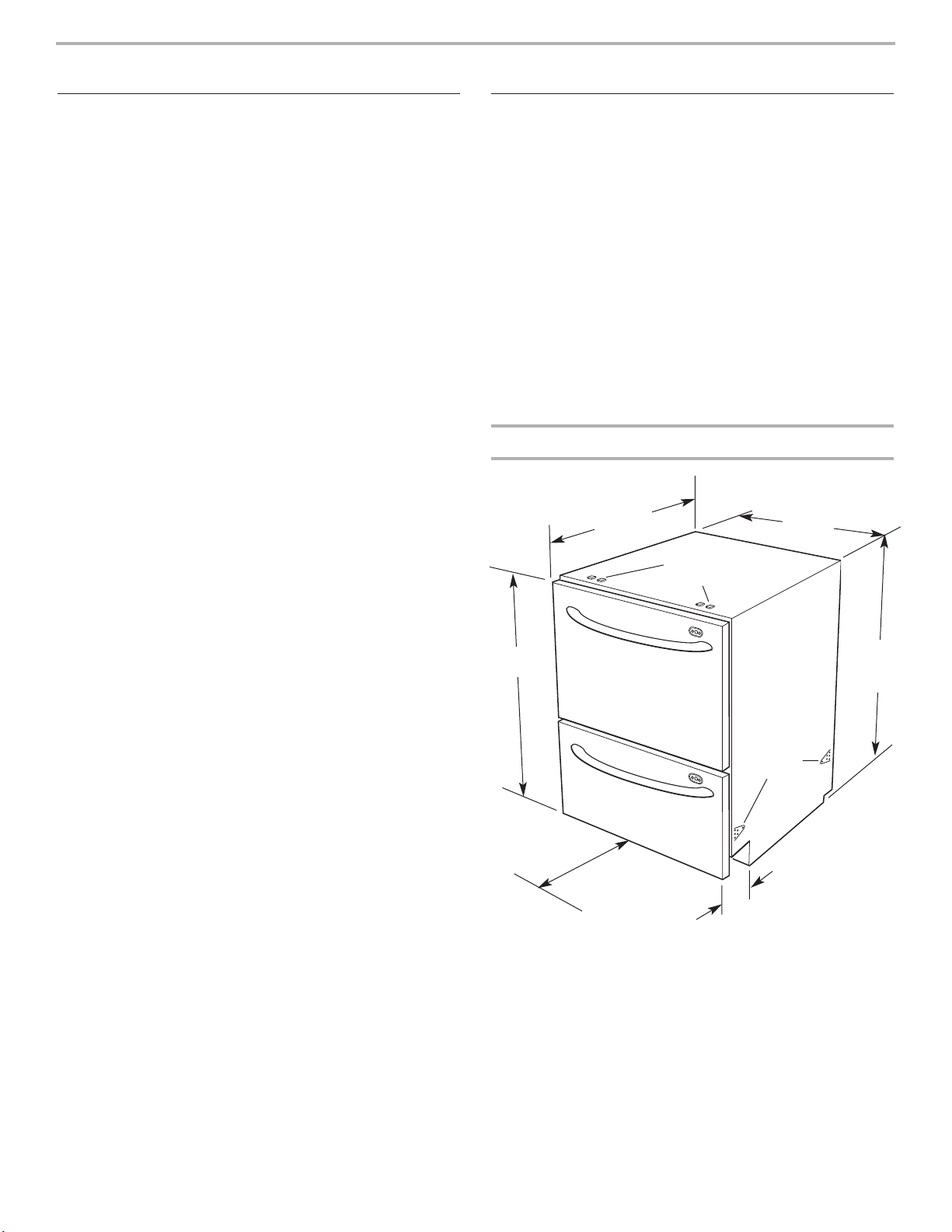
Product dimensions
22-7/16" *
(57 cm)
raised tabs for
optional top
attaching brackets
30" ***
(76.2 cm)
23-7/16"
(59.5 cm)
32-3/16" -
34-1/2"
(81.8 cm -
87.8 cm)
side
attaching
tabs
20-15/32"
(52 cm)
drawer open
* If custom wood panels are to be used, the product depth is specified with an
11/16" (18 mm) door panel thickness.
** Toe panel depth: Factory supplied, 2– 4-3/8" (5 – 11 cm); Custom wood, 5"
(12.7 cm) less the toe panel thickness for integrated. Minimum panel thickness
using the supplied screws is 3/8" (9 mm).
*** Door front height: Factory supplied – 30" (76.2 cm); Custom wood – 28-1/4"
(71.8 cm) minimum.
NOTE: Product shown with front panels for dimension purposes.
2"– 4-3/8" **
(5 cm – 11 cm)
3
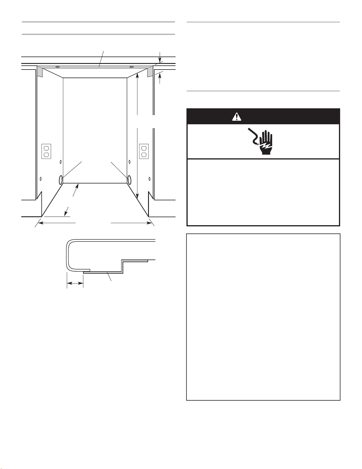
Cabinet dimensions/requirements
Water Supply Requirements
Utility hole:
1-1/2" (3.8 cm) dia.
hole, either side –
immediately adjacent
22-7/8"
(58.0 cm)
23-5/8"* (60.0 cm)
moisture
protection tape
to corner.
4"
(10 cm)
32-5/16"– 34-5/8"
(82.0 cm – 88.0 cm)
For dishwasher:
■ Hot water line with 4.3-145 psi (30-1000 kPa) water pressure.
■ 120°F (48.8°C) water at dishwasher.
■ An easily accessible valve with 3/8" compression fitting must
be installed in the hot water supply line.
Electrical Requirements
WARNING
Electrical Shock Hazard
Plug into a grounded 3 prong outlet.
Do not remove ground prong.
Do not use an adapter.
Do not use an extension cord.
Failure to follow these instructions can result in death,
fire, or electrical shock.
typical
installation
1/2" (12.7 mm) from
front of countertop
tape
countertop
moisture
protection tape
The 3 prong grounded outlet must be installed within 6"
(15.2 cm) to 18" (45.7 cm) of the cabinet side wall.
NOTE: The power outlet must be accessible after installation.
It is recommended that wood cabinetry surrounding the
dishwasher be sealed with an oil-based paint or moisture-proof
polyurethane to prevent possible damage from humidity.
The utility hole must be located as shown. If the hole is not
located as shown, the hoses will prevent the dishwasher from
being pushed back all the way into the cavity. Make sure the
edges of the utility hole are smooth or covered. If the utility hole
is through a metal cabinet, the hole must be protected with the
edge protector provided.
*IMPORTANT: Custom wood door panels, if used, may be wider
than the dishwasher to match surrounding cabinets. The 23-5/8"
(60.0 cm) must be increased so that there is a 1/4" (6.4 mm)
clearance between the cabinet side and panel edge.
For corner installation, there must be a 1/2" (12.7 mm) space
between the adjacent cabinet doors (i.e. door knobs) and open
dishwasher drawer.
GROUNDING INSTRUCTIONS
• For a grounded, cord-connected dishwasher:
The dishwasher must be grounded. In the event of a
malfunction or breakdown, grounding will reduce the risk of
electric shock by providing a path of least resistance for
electric current. The dishwasher is equipped with a cord
having an equipment-ground conductor and a grounding
plug. The plug must be plugged into an appropriate outlet
that is installed and grounded in accordance with all local
codes and ordinances.
WARNING: Improper connection of the equipment-
grounding conductor can result in a risk of electric shock.
Check with a qualified electrician or service representative if
you are in doubt whether the dishwasher is properly
grounded. Do not modify the plug provided with the
dishwasher; if it will not fit the outlet, have a proper outlet
installed by a qualified electrician.
• For a permanently connected dishwasher:
The dishwasher must be connected to a grounded metal,
permanent wiring system, or an equipment-grounding
conductor must be run with the circuit conductors and
connected to the equipment-grounding terminal or lead on
the dishwasher.
SAVE THESE INSTRUCTIONS
A 120-volt, 60 Hz, AC-only, 15 amp fused electrical supply is
required. (Circuit breaker or time-delay fuse is recommended.) It
is recommended that a separate circuit serving only this
appliance be provided.
4
Garbage Disposer:
If you plan to install a garbage disposer, an additional separate
120-volt, 60 Hz, AC-only, 15 or 20 amp fused electrical supply is
required.
INSTALLATION INSTRUCTIONS
Recommended ground method
This appliance must be grounded. This appliance is equipped
with a power supply cord having 3 prong ground plug. To
minimize possible shock hazard, the cord must be plugged into a
mating prong ground-type outlet, grounded in accordance with
local codes and ordinances.
Prepare Cabinet Opening
1. Prepare the cabinet opening by applying self-adhesive
moisture protection tape to the dry dust-free underside
of the countertop.
countertop
moisture
tape
1/2" (12.7 mm) from
front of countertop
2. Turn off water supply.
3. Decide which attaching tabs to use to secure the dishwasher.
The four side attaching tabs are recommended.
4. If the countertop material permits and the optional top
attaching brackets will be used, install them now.
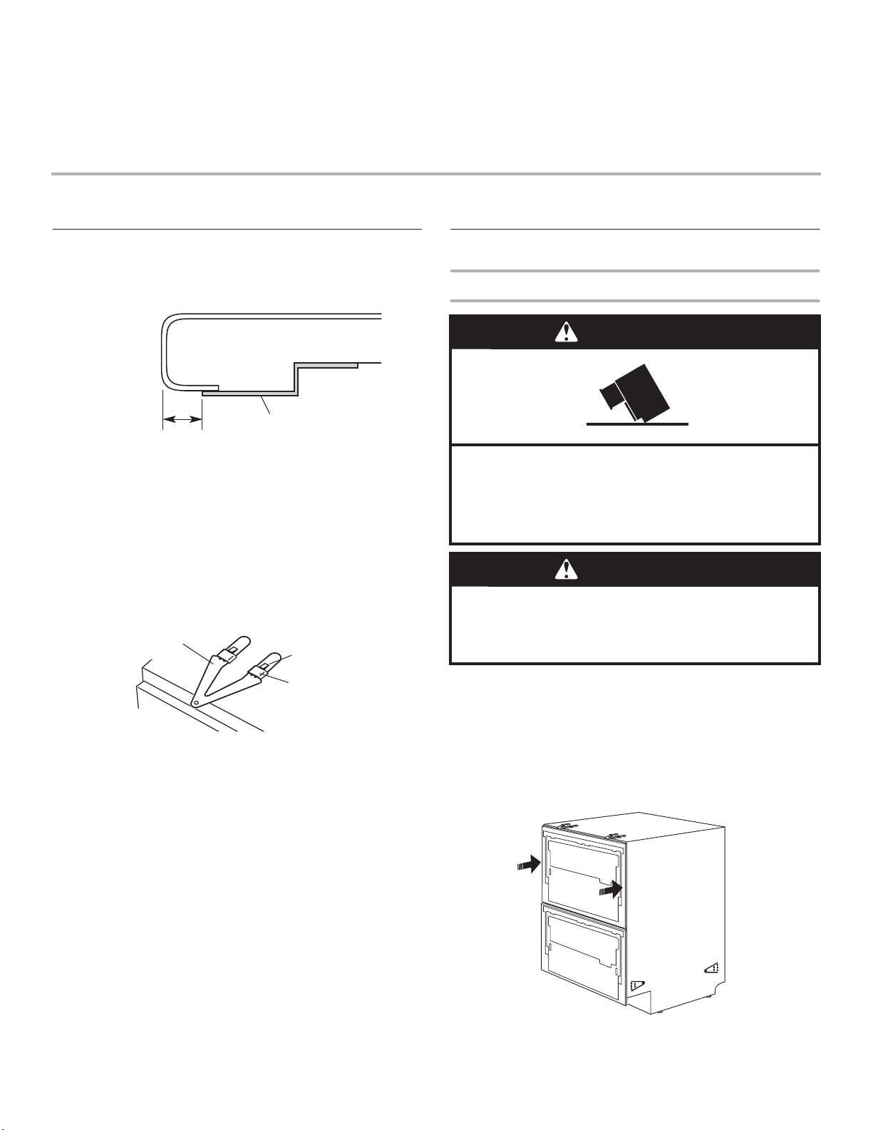
Slide the brackets under the raised tabs. Using the flat side of
the side cutting pliers, lightly tap the brackets into place.
Make sure the locking tabs on the brackets are completely
passed through the raised tabs on the dishwasher.
mounting
bracket
protection tape
locking tab
Electrical Connection
Option 1: Power Supply Cord Method
WARNING
Tip Over Hazard
Do not use dishwasher drawer until inside cabinet
opening.
Doing so can result in serious injury or cuts.
WARNING
Excessive Weight Hazard
Use two or more people to move and install dishwasher.
Failure to do so can result in back or other injury.
raised tab
5. If using the factory-installed power cable and plug, go to
“Electrical connection” section, Option: 1: Power Supply Cord
Method.
If direct wiring the dishwasher, go to “Electrical connection”
section, Option: 2: Direct Wiring Method.
1. Place cardboard or other protective covering on the floor in
front of cabinet opening. Place the dishwasher on covering.
2. Begin to route the hoses and power supply cord through the
utility hole in the cabinet.
3. Push dishwasher partway into the opening.
IMPORTANT: Push against the outside edges of drawers as
shown. Do not push against the center of the drawers.
5
4. As the dishwasher is being pushed into the opening, slowly
pull the inlet hose, drain hoses and power supply cord
through the utility hole.
5. Remove the strap from upper drawer.
Go to “If Installing Flexible Trim Pieces” section.
Option 2: Direct Wiring Method
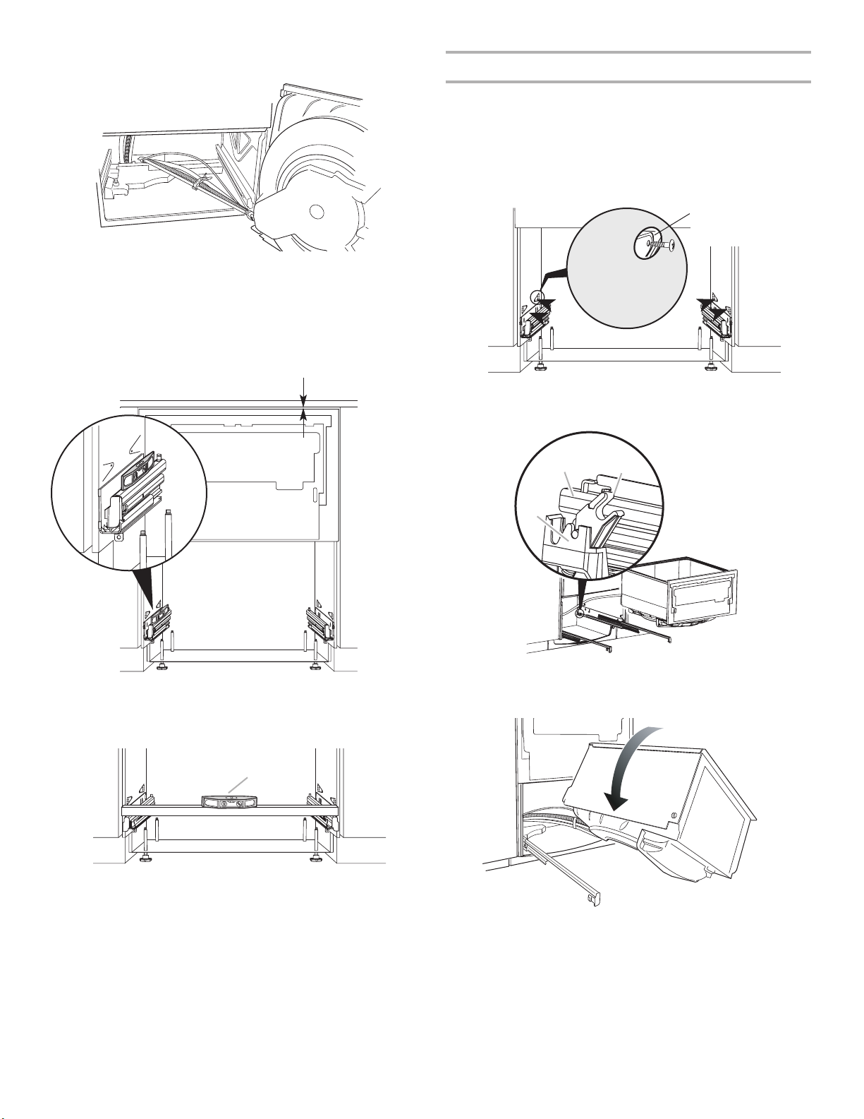
6. Rotate drawer to the right onto its side and place on the
protective cover.
WARNING
Electrical Shock Hazard
Disconnect electrical power at the fuse box or circuit
breaker box before installing dishwasher.
Failure to do so can result in death or electrical shock.
WARNING
Excessive Weight Hazard
Use two or more people to move and install dishwasher.
Failure to do so can result in back or other injury.
1. Place cardboard or other protective covering on the floor in
front of cabinet opening. Place the dishwasher on covering.
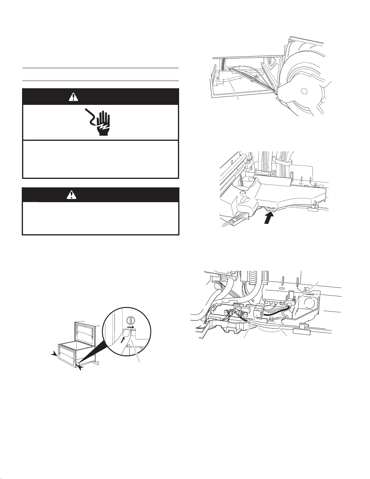
2. Disconnect power.
3. Open the bottom drawer.
4. Press in the right-hand runner clip and push it back about 6"
(15.2 cm). Repeat with the left-hand runner clip.
NOTE: When removing the drawer there is limited range of
movement due to the attached water hoses.
electrical cover
7. Slide the left-hand runner back into the dishwasher.
8. The electrical cover is located in the back left corner.
Use a flat blade screwdriver to press the release button. Slide
the cover to the right and then pull up.
electrical cover
press
release button
Remove factory-installed power cord.
1. Disconnect the black and white wires of the power cord from
the terminal block.
strain relief
runner clip
5. Lift the right edge of the drawer off its runner. Slide that runner
back into the dishwasher. Lift the drawer completely off the
left-hand runner.
6
terminal block
2. Use a 7 mm socket wrench to remove the green ground
screw. Remove the green ground wire.
3. Use a Phillips screwdriver to remove the strain relief screw.
Open the strain relief.
4. Pull the power supply cord off the dishwasher through the
back of the dishwasher.
5. Close the strain relief and replace screw so it does not
interfere with the electrical cover.
green ground screw
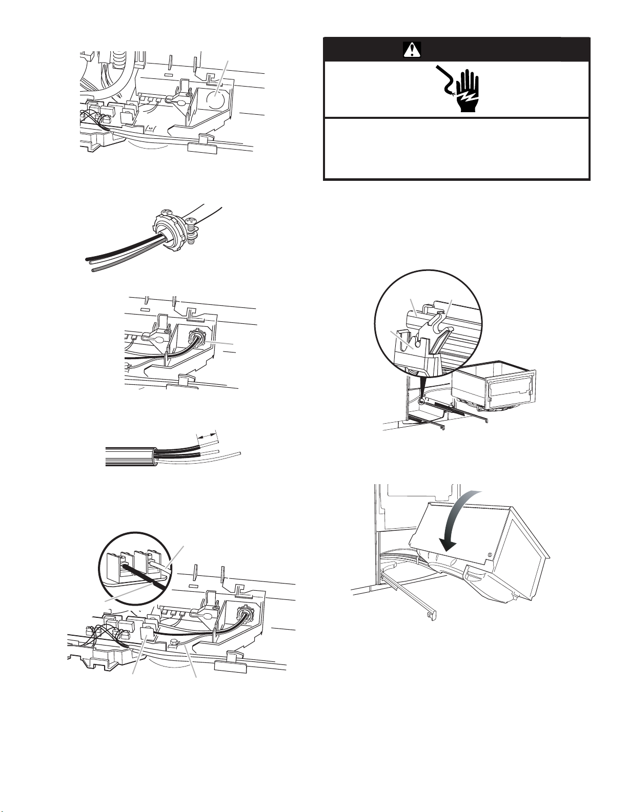
6. Remove the house wiring knockout.
knockout
WARNING
Electrical Shock Hazard
Connect ground wire to green ground screw.
7. Run the house wiring through the conduit connector (not
supplied) and into the dishwasher through the knockout
opening.
8. Secure the conduit connector in the knockout opening.
conduit
connector
9. From the house wiring, strip 1/2" (13 mm) of insulation off of
each wire.
1/2" (13 mm)
10. Insert the black supply wire and the white neutral wire into
the appropriate wire clamp on the terminal block. Securely
tighten the clamps.
terminal block
white wire
Failure to do so can result in death or electrical shock.
11. Place the ground wire under the green ground screw. Use a
7 mm socket wrench to securely tighten the green ground
screw.
12. Tighten the conduit connector. Replace electrical cover.
13. Pull the bottom drawer runners all the way out. Make sure the
latches on the back of each drawer runner are facing forward.
drawer
runner
latch
bracket
latch
14. If the bottom drawer was rotated, rotate the drawer to unwind
the hoses and then put the drawer on the runners, making
sure the hoses are looping upward.
black wire
terminal block
15. Make sure both runner clips have snapped into place. If they
have not, pull the runner clips forward until they do.
16. Close the bottom drawer.
ground wire
7
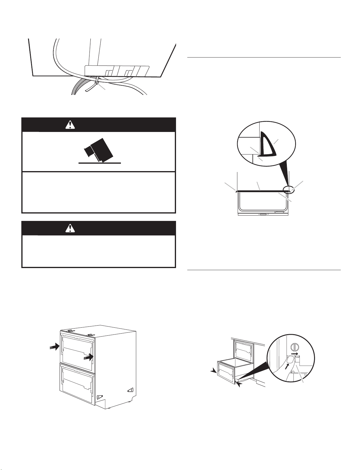
17. Use the side cutting pliers to cut the cable tie securing the
hoses and power supply cord to the back of the dishwasher.
back of
dishwasher
cable tie
18. Completely remove the power supply cord and save it, in
case a power cord installation is needed in the future.
22. As the dishwasher is being pushed into the opening, slowly
pull the inlet hose and drain hoses through the utility hole. Let
the house wiring gather behind the dishwasher.
23. Remove the strap from upper drawer.
If Installing Flexible Trim Pieces
If the cabinet opening is 24" wide x 34-1/2" high (61.0 cm x
87.6 cm), flexible trim pieces can be attached along the top and
sides of the dishwasher. Top and side trim pieces are different
lengths.
1. Open the drawers to expose the chassis trim.
2. Center the flexible trim pieces.
WARNING
Tip Over Hazard
Do not use dishwasher drawer until inside cabinet
opening.
Doing so can result in serious injury or cuts.
WARNING
Excessive Weight Hazard
Use two or more people to move and install dishwasher.
Failure to do so can result in back or other injury.
19. Place cardboard or other protective covering on the floor in
front of cabinet opening. Place the dishwasher on covering.
20. Begin to route the hoses through the utility hole in the cabinet.
IMPORTANT: Push against the outside edges of drawers as
shown. Do not push against the center of the drawers.
21. Push dishwasher partway into the opening.
side trim
chassis
trim
edge
side trim
piece
3. If using the optional top attaching brackets, place the trim
pieces under the attaching brackets.
4. Remove trim pieces backing paper to expose the adhesive.
5. Place the trim pieces on the trim and press.
6. Finish pushing dishwasher into opening.
top trim
piece
open drawer
piece
lip
side trim
piece
chassis trim
edge
Install Dishwasher
1. Leave protective cover on floor.
2. Open the bottom drawer.
3. Press in the right-hand runner clip and push it back about 6"
(15.2 cm). Repeat with the left-hand runner clip.
NOTE: When removing the drawer there is limited range of
movement due to the attached water hoses.
runner clip
4. Lift the right edge of the drawer off its runner. Slide that runner
back into the dishwasher.
5. Lift the drawer completely off the left-hand runner.
8
6. Rotate the drawer to the right onto its side and place on the
protective cover.
7. Slide the left-hand runner back into the dishwasher.
8. Reach inside the dishwasher to adjust the feet using a 5 mm
open end, box end, or socket (if space permits) wrench.
Adjust for cabinet height and level. Place a level on the drawer
runners. Level the dishwasher to within 3/32" (2.4 mm) from
front to back.
3/32" (2.4 mm) minimum
clearance to underside of counter
Choose attachment option
Option 1: Side attachment
1. The dishwasher side attaching tabs are accessed through
holes in the sound insulation.
IMPORTANT: For best installation, use all four attaching tabs.
2. Secure the attaching tabs to the cabinet using #8 Phillips
head screws.
side
mounting
bracket
3. Pull the bottom drawer runners all the way out. Make sure the
latches on the back of each drawer runner are facing forward.
drawer
runner
latch
9. Place a level across the drawer runners. Level the dishwasher
to within 3/32" (2.4 mm) from side to side.
level
latch
bracket
4. If the bottom drawer was rotated, rotate the drawer to unwind
the hoses and then put the drawer on the runners, making
sure the hoses are looping upward.
5. Make sure both runner clips have snapped into place. If they
have not, pull the runner clips forward until they do.
6. Close the bottom drawer.
9
Option 2: Top attachment
1. If the top attaching brackets are used, open the top drawer
slightly.
2. Screw the top attaching brackets to the underside of the
counter with two #8 Phillips head screws.
IMPORTANT: The top attaching brackets can accommodate
a maximum 3/4" (19 mm) vertical gap.
top attaching bracket
3. Close the top drawer.
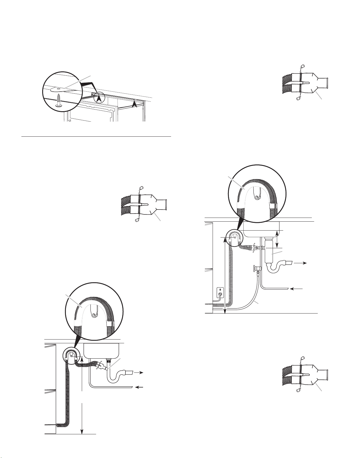
Install the Drain Hose
Option 1: Sink drain waste tee connection
1. Route the drain hoses as shown and press the hoses into
the drain hose support.
2. Decide if the drain hoses need to be trimmed. If they do,
trim them.
3. Slip a wire clip over each drain
hose. Push the hoses into the
drain hose connector firmly,
5 clicks.
4. Position the wire clips between
the two positioning ribs on the
wire clip
drain hose connector.
5. Attach the drain hose connector to the waste tee using
the supplied hose clamp.
6. Attach the drain hose support bracket to the cabinet with
a #8 Phillips head screw at the height shown below.
NOTE: The drain hose connector must not support the weight
of excess hose length. Keep hoses as fully extended as
possible.
drain hose
support
wire clip
drain hose
connector
Option 2: Garbage disposal connection
1. Route the drain hoses as shown and press the hoses
into the drain hose support.
2. Decide if the drain hoses need to be trimmed. If they do,
trim them.
3. Slip a wire clip over each drain
wire clip
hose. Push the hoses into the
drain hose connector firmly,
5 clicks.
4. Position the wire clips between
the two positioning ribs on the
drain hose connector.
wire clip
drain hose
connector
5. Attach the drain hose connector to the garbage disposal
using the supplied hose clamp.
6. Attach the drain hose support bracket to the cabinet with
a #8 Phillips head screw at the height shown below.
NOTE: The drain hose connector must not support the
weight of excess hose length. Keep hoses as fully extended
as possible.
drain hose
support
6" (15.2 cm)
minimum
garbage
disposal
valve
(70 cm – 82 cm)
27-1/2" – 32-1/4"
water supply
waste
10
27-1/2" – 32-1/4"
(70 cm – 82 cm)
waste tee
waste
water supply
8" (20.3 cm) min. bend
radius from valve
Option 3: Air break connection
1. Route the drain hoses as shown.
2. Decide if the drain hoses need to be trimmed. If they do,
trim them.
3. Slip a wire clip over each drain
wire clip
hose. Push the hoses into the
drain hose connector firmly,
5 clicks.
4. Position the wire clips between
the two positioning ribs on the
drain hose connector.
wire clip
drain hose
connector
 Loading...