

KitchenAid KUD-22 User Manual

UitchenAtd*
KUD-22 SERIES
I
tJ
J
DISH WASHERS
--i+
;/
r
INSTA L LA T/ON
INSTRUCTIONS

THIS PAGE
BEFORE STARTING:
Please read these rnstallation instructions COMPLETELY AND CAREFULLY. They will save you time, work, and
help to ensure optimum dishwasher performance. OBSERVE ALL LISTED WARNINGS AND CAUTIONS.
For Replacement Installation - Review these complete instructions to be sure that previous connections are
compatible.
For New Installations - Plumbrng and electrical connections must be provided before the dishwasher is moved
Into place.
These instructions are intended for use by qualified workers who will observe all local codes and ordinances for
plumbing connections as well as local codes and/or the Canadian Electrical Code for’electrical connections.
DO NOT REMOVE THE GALVANIZED STEEL SIDE AND BOTTOM PANELS. THE REMOVAL OF
THESE ITEMS WILL VOID THE C.S.A. CERTIFICATION AND INCREASE THE DANGER OF FIRE AND
ELECTRICAL SHOCK.
I
YOU WILL NEED THESE TOOLS:
Phillrps Screwdriver
Flat Blade Screwdnver
Adjustable Wrenches (2) (if copper fittings are used)
Pipe Wrenches (2) (if galvanized or iron fittings are used)
Nut Driver or Socket Set
Wrre Cutters
Tape Measure
Spirit/Bubble Lever
Electrrc Drrll
1” (25 mm) Drill BII or Hole Saw
58 (3 mm) Drill Bit
Square
. . .
5/a” (16 mm) OD Copper Tubing (of sufficient length for your installation), Shut-off Valve, and Fittings (for copper
l/i” (13 mm) Pipe (of sufficient length for your installation), Shut-off Valve, and Fittings (for galvanized water
%I” (9.5 mm) NPT 90° Street Elbow
90° Compression Elbow: l/z” (13 mm) Tube End & 3/e” (9.5 mm) NPT male pipe end (for copper water supply
l/2” (13 mm) NPT 90° Street Elbow and
9/,6” (14 mm) ID Heat and Detergent Resistant Rubber Hose and Clamps or s/a” (16 mm) OD Copper Tubing
10” (250 mm) Length of 518” (16 mm) OD Soft Copper Tubing, Formed Into a Semicircle (if high loop drain
115 Volt, 15 Amp, 2 Wire, Properly Grounded, Branch Circuit
x/4” (19 mm) Strain Relief Bushing for Electrical Supply Cable.
AA/D THESE MATERIALS:
water supply line)
supply line)
line only) See Fig. 13 page 10.
l/2”
(13 mm) NPT female x 3/a” (9.5 mm) NPT male reducing adapter
(for galvanized water supply line only)
and Fittings (of sufficient length to accommodate your drain line)
is required - see page 7)
-3-
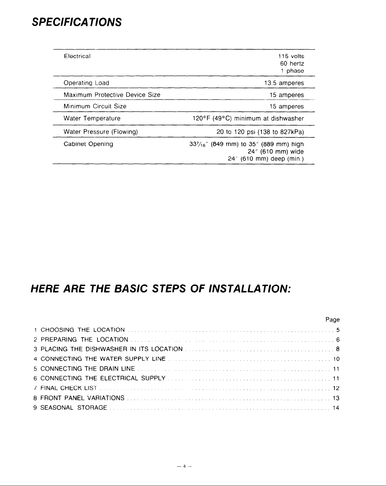
SPECIFICATIONS
Electrical
Operating Load
Maximum Protective Device Size
Minimum Circuit Size
Water Temperature
Water Pressure (Flowing) 20 to 120 psi (138 to 827kPa)
Cabinet Opening 337/16” (849 mm) to 35” (889 mm) high
120°F (49°C) minimum at dishwasher
24” (610 mm) wide
24” (610 mm) deep (min.)
115 volts
60 hertz
1 phase
13.5 amperes
15 amperes
15 amperes
HERE ARE THE BASIC STEPS OF INSTALLATION:
1 CHOOSING THE LOCATION
2 PREPARING THE LOCATION
3 PLACING THE DISHWASHER IN ITS LOCATION
4 CONNECTING THE WATER SUPPLY LINE
5 CONNECTING THE DRAIN LINE
6 CONNECTING THE ELECTRICAL SUPPLY
7 FINAL CHECK LIST
8 FRONT PANEL VARIATIONS
9 SEASONAL STORAGE
-4-
Page
5
10
11
11
.., 12
.., 13
14
I
For easy access to plumbing, it is most convement to have your dishwasher located near the kitchen sink.
Any built-in dishwasher must be fully enclosed on the top, both sides, and the back. Therefore, the cabinet space
below your kitchen counter is probably the best location. If the dishwasher is being installed at the end of a cabinet
or free standing then side panels and a wood top can be purchased from your KitchenAid dealer to enclose the
dishwasher.
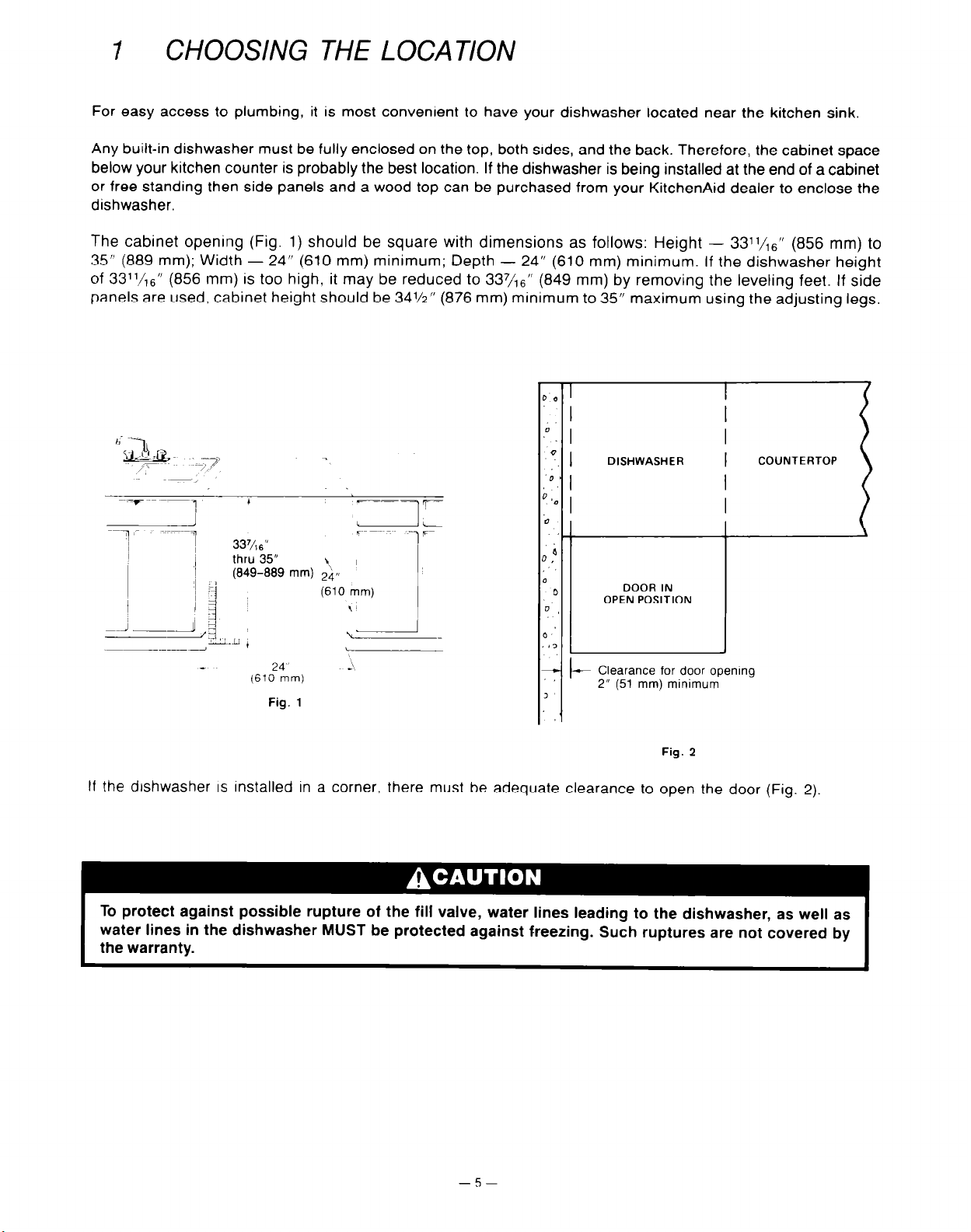
The cabinet opening (Fig. 1) should be square with dimensions as follows: Height - 3311/,6” (856 mm) to
35” (889 mm); Width - 24” (610 mm) minimum; Depth - 24” (610 mm) minimum. If the dishwasher height
of 33”/
panels are used, cabinet height should be 34%” (876 mm) minimum to 35” maximum using the adjusting legs.
CHOOSING THE LOCA T/ON
,6” (856 mm) is too high, it may be reduced to 337h6” (849 mm) by removing the leveling feet. If side
) 0
I
.i[ 1
I-
If the drshwasher
‘1
‘I
COUNTERTOP
337/,6”
thru 35”
(849-889 mm)
p. I
.D *
3
DISHWASHER
Clearance for door openmg
I-
2” (51 mm) minimum
1
Fig. 2
IS
installed in a corner, there must be adequate clearance to open the door (Fig. 2)
To protect against possible rupture of the fill valve, water lines leading to the dishwasher, as well as
water lines in the dishwasher MUST be protected against freezing. Such ruptures are not covered by
the warranty.
I
-5-
I

2
Access holes in the cabmets, floor, or rear wall for the hot water supply line, drain line, and electrical supply must
be located within the shaded area in Fig. 3 in order to avoid Interference with the dishwasher frame or other
components.
PREPARING THE LOCATION
HOT WATER SUPPLY LINE
PLUMBING CONNECTIONS MUST COMPLY WITH APPLICABLE SANITARY, SAFETY, AND PLUMBING
CODES.
Water supply should be 120°F (49OC) minimum at the dishwasher. (Refer to Use & Care Guide.)
The hot water supply line should be 5%” (16 mm) OD copper tubing or
dishwasher fill valve has a l/z” (13 mm) NPT female connection.
Atter determining where the water supply line will enter the dishwasher opening, drill a 1” (25 mm) access
hole and run the line to the approximate fill valve location as shown in Fig. 4.
Fig. 3
l/2”
(13 mm) galvanized pipe. The
I
4” (102 mm)
- (Frbm floor)
6” (152 mm)
Fig. 4
For service convenience, a shut-off valve (not supplied) should be installed in the supply line in a readily accessible
location (such as beneath the sink) and a union (not supplied) should be installed in the supply line near the
dishwasher fill valve.

To prevent heat damage to the fill valve, ALL solder connections must be made BEFORE the water line
is connected to the dishwasher.
DRAIN LINE
The drain line should be 9/,6” (14 mm) ID (minimum) flexible hose or 5,‘~” (16 mm) OD copper tubing. Flexible
hose must be resistant to heat and detergent and may be obtained from a plumbing, hardware, or automotive
supply outlet. DO NOT use any fittings anywhere in the drain line that are less than
l/2”
(13 mm) ID. The
access hole for the drain line should be 1’ (25 mm).
If drain line is copper, clamp a 12” (305 mm) length of g/
16” (14 mm) ID flexible hose (heat and detergent
resistant) to the end of the copper tubing. This will facilitate connection of the drain line to dishwasher check valve.
If the drain line is going to be connected to a food waste disposer, BE SURE to remove the knockout or plug
from the fitting on the disposer before connecting drain line. Rubber adapter fitting may be required.
(KitchenAid part number 115739 or available from local hardware or plumbing stores.)
Typical drain connections to sink plumbing are shown in Fig. 5 & 6.
.
Dra ‘1 or disposer connectlon
’ ~~ --y-- ---
~~~ -__
Air Gap
k--IL
“If &a,” hne IS flex;bie-hose
lhls dlmenslon IS
22” (559 mm)
If drain line IS copper.
the copper should be
12” (305 mm) plus a
12” (305 mm) length of
flexible hose attached to
Ihe end
local code) IS shown in
(;84r&rn)
Fig. 6.
Fig. 6
I
I
_ 4”
(108 r7m;
Fig. 5
I
J , ‘LJ
Typlcal drain connection to an air gap (If required by
IF DRAIN IS ROUTED TO A CONNECTION POINT LESS THAN 20” (508 mm) ABOVE THE FLOOR,
THE DRAIN LINE MUST BE MADE TO FORM A HIGH LOOP TUBE (SHOWN IN FIG. 7).
FAILURE TO PROVIDE EITHER THE PROPER DRAIN CONNECTION HEIGHT (20” (508 mm) ABOVE
FLOOR LEVEL) OR A 20” (508 mm) HIGH LOOP WILL RESULT IN IMPROPER DRAINING OF THE
MACHINE WHICH MAY CAUSE DAMAGE TO THE MACHINE.
TO FORM THE HIGH LOOP TUBE, SEE INSET ON FIG. 7. MAKE SURE THAT NO KINKS DEVELOP
IN THE HOSE OR COPPER TUBING.
II drain lme IS copper,
the copper should be
12” (305 mm) plus a
12” (305 mm) lenglh of
flextble hose attached lo
the end
- a"-
(108
mm)
Fig. 7
VB” (16 mm) O.D. Copper tubing
must be at least 20” (506 mm)
I above floor.
‘If drain line IS flexible hose
this dlmenslon IS
22”
(559 mm)
If drain line IS copper,
the copper should be
12” (305 mm) plus a
12” (305 mm) length of
flexible hose allached 10
Ihe end

ELECTRICAL AND GROUNDING CONNECTIONS MUST COMPLY WITH THE CANADIAN ELECTRICAL
CODE AND/OR OTHER LOCAL CODES.
DISCONNECT ELECTRICAL POWER SUPPLY.
TOt? electrical supply must be a 115 volt, 15 amp, properly grounded, positloned as shown in Fig. 8, and should
be Installed by a qualified electrician. No other appliances or outlets should be on this circuit.
-+I
3” I-
176
mm)
Fig. 0
To access dishwasher connections:
Remove the two screws located on each side and
below the lower panel. Pull out the bottom of the panel
to unhook tabs from frame. Lift the panel up and off.
Set aside. Pull adjustable kickboard straight off.
5
Adjustable
klckboard
Fig. 9
3
PLACING THE DISHWASHER IN ITS LOCATION
The adjustable klckboard and lower panel (Fig. 9) must be removed for access to dishwasher connections. Remove
the kickboard (5) by removing the two screws (one with lock washer) that secure it. Remove two screws (1) and
pull out the bottom of lower panel to unhook tabs (2) from frame. Remove the lower panel by pulling it downward
tO slide panel flanges (3) from behind the support channel (4).
Set ?he dishwasher if-: front of the orepared cabinet opening and evenly adjust the four leveling feet to the desired
herqh!
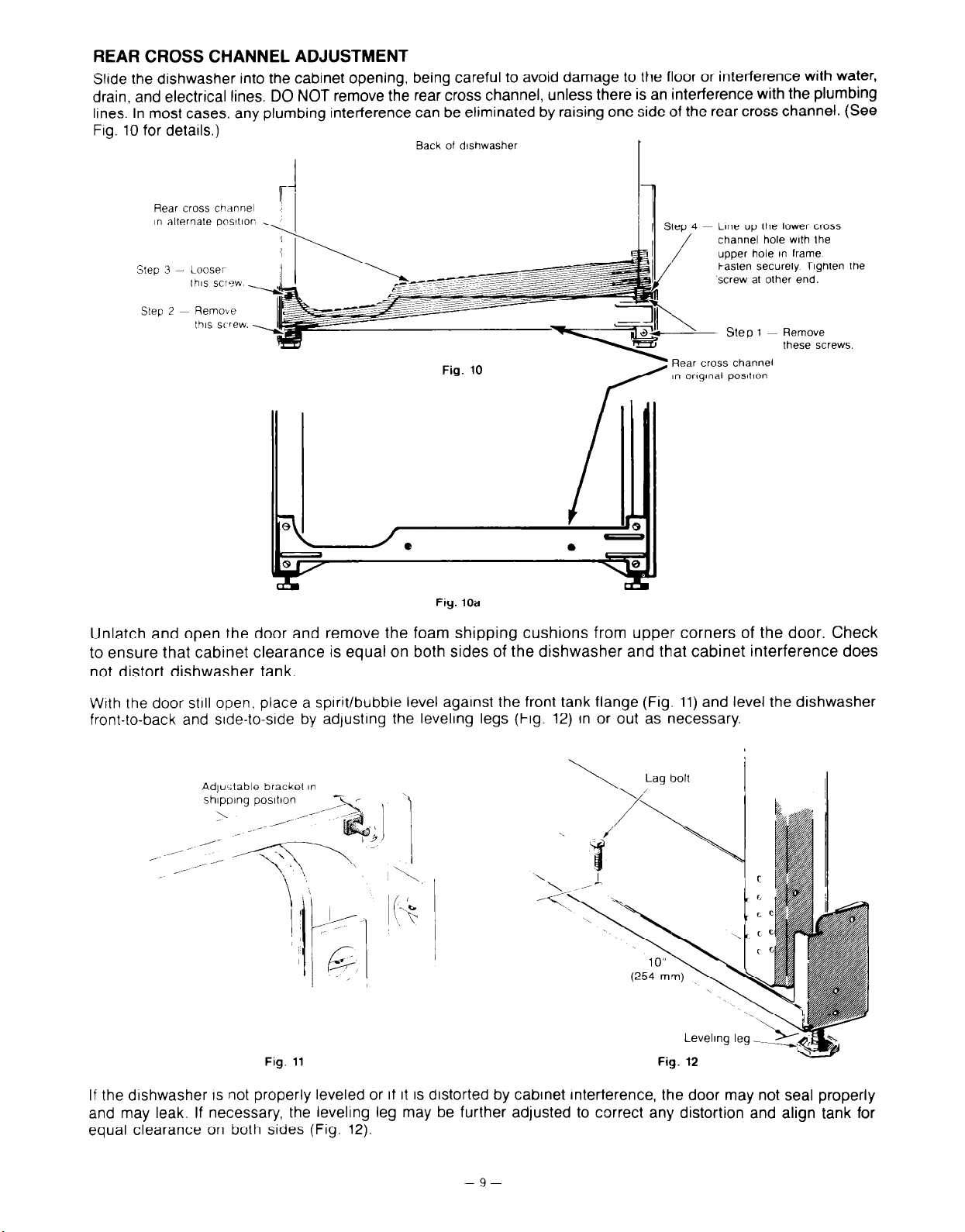
REAR CROSS CHANNEL ADJUSTMENT
Slide the dishwasher into the cabinet opening, being careful to avoid damage to the floor or interference with water,
drain, and electrical lines. DO NOT remove the rear cross channel, unless there is an interference with the plumbing
lines. In most cases, any plumbing interference can be eliminated by raising one side of the rear cross channel. (See
Fig. 10 for details.)
Back of dlshwasher
Rear cross channel
I” alternate pos~llon
SteD
Looser
lhls SC’YW _
Line up the lower cross
channel hole with ihe
upper hole in frame
Fasten securely Tighten
.screw at other end.
the
SleD
Remove
lhls screw. _
Fig. 10a
- Step 1 ~ Remove
these screw’
cross channel
lglnal posltlon
s.
Unlatch and open the door and remove the foam shipping cushions from uppelr corners of the door. Check
to ensure that cabinet clearance is equal on both sides of the dishwasher and that cabinet interference does
not distort dishwasher tank.
With the door still open, place a spirit/bubble level against the front tank flange (Fig. 11) and level the dishwasher
front-to-back
and side-to-side by adjusting the leveling legs (Fig. 12) In or out as necessary.
Adjustable bracket in
shlpolng posltlon
>
Fig. 11
If the dishwasher is not properly leveled or if it is distorted by cabinet interference, the door may not seal properly
and may leak. If necessary, the leveling leg may be further adjusted to correct any distortion and align tank for
equal clearance on both sides (Fig. 12).
-9-
 Loading...