

KitchenAid KUD01, KAD-7 User Manual
TECHNICAL EDUCATION
KAD-7
For the way it's made.™
Inc.
KUD01
STAINLESS STEEL
48
DISHWASHER
JOB AID 4317288

INTRODUCTION
This Job Aid,
mation on the operation, diagnosis and repair of the KitchenAid KUD01 series Stainless Steel Dishwasher.
KUD01 STAINLESS STEEL DISHWASHERS
tion on design, features, operation, troubleshooting, and repair procedures.
KUD01 STAINLESS STEEL DISHWASHERS
has been compiled to provide the most recent informa-
, Part No. 4317288 provides specific infor-
GOALS AND OBJECTIVES
The goal of this Job Aid is to provide detailed information that will enable the service technician to
properly diagnose malfunctions and repair the KUD01 Stainless Steel Dishwasher.
The objectives of the Job Aid are:
The service technician will -
• Understand proper safety precautions.
• Successfully troubleshoot and diagnose malfunctions.
• Successfully perform necessary repairs.
• Successfully return the dishwasher to proper operational status.
TO THE INSTRUCTOR/INDEPENDENT STUDENT
This Job Aid is designed to be used with the video tape,
Part No. 4317287V.
ERS,
KITCHENAID CORPORATION ASSUMES NO RESPONSIBILITY
FOR ANY REPAIRS MADE ON OUR PRODUCTS BY ANYONE
OTHER THAN AUTHORIZED SERVICE TECHNICIANS.
KUD01 STAINLESS STEEL DISHWASH-
© 2000 KitchenAid, Inc., St. Joseph, MI 49013
II

-- NOTES --
TABLE OF CONTENTS
Section One
INSTALLATION CONSIDERATIONS .................................................. 1
GENERAL CONSIDERATION.................................................................1
Section Two
THEORY OF OPERATION ................................................................. 3
CONTROL PANELS ................................................................................3
CYCLES AND CYCLE VARIATIONS ......................................................4
AUTOMATIC PURGE FILTRATION ........................................................ 5
CANCELING A CYCLE ........................................................................... 6
CHANGING A CYCLE .............................................................................6
OPTION SELECTIONS............................................................................7
CYCLE STATUS INDICATORS............................................................... 9
FUNCTION DESCRIPTION ................................................................... 10
Section Three
COMPONENT ACCESS ...................................................................13
COMPONENT LOCATION ....................................................................13
ACCESSING COMPONENTS IN THE DOOR .......................................14
ACCESSING COMPONENTS INSIDE THE TUB ..................................17
SERVICING THE SUMP ASSEMBLY ...................................................2 0
Section Four
TROUBLESHOOTING AND DIAGNOSIS ..........................................25
TROUBLESHOOTING CHART..............................................................25
COMMON CYCLE TIME CHART...........................................................27
HOW TO USE COMMON CYCLE TIME CHART .................................. 28
COMMON CYCLE TIME CHART NOTES .............................................32
RAPID ADVANCE FEATURE & DIAGNOSTIC CYCLES .....................36
DIAGNOSTIC CYCLE TIME CHART..................................................... 37
Section Five
TECH TIPS .................................................................................... 39
WIRING DIAGRAM ................................................................................39
STRIP CIRCUITS ...................................................................................40
ELECTRONIC CONTROL CONNECTOR PINS ....................................41
MODEL/SERIAL NUMBER PLATE .......................................................42
MODEL SPECIFIC SERVICE PARTS TABLE ......................................43
KEY PAD MATRIX.................................................................................43
SPECIFICATIONS .................................................................................44
WATER USAGE.....................................................................................44
WHAT TO DO IF THE DISHWASHER DOOR DOES NOT OPEN ........45
46
III
SAFETY
! WARNING
ELECTRICAL SHOCK HAZARD
Disconnect power before servicing the dishwasher.
Replace all panels before operating the dishwasher.
Failure to do so can result in death or electrical shock.
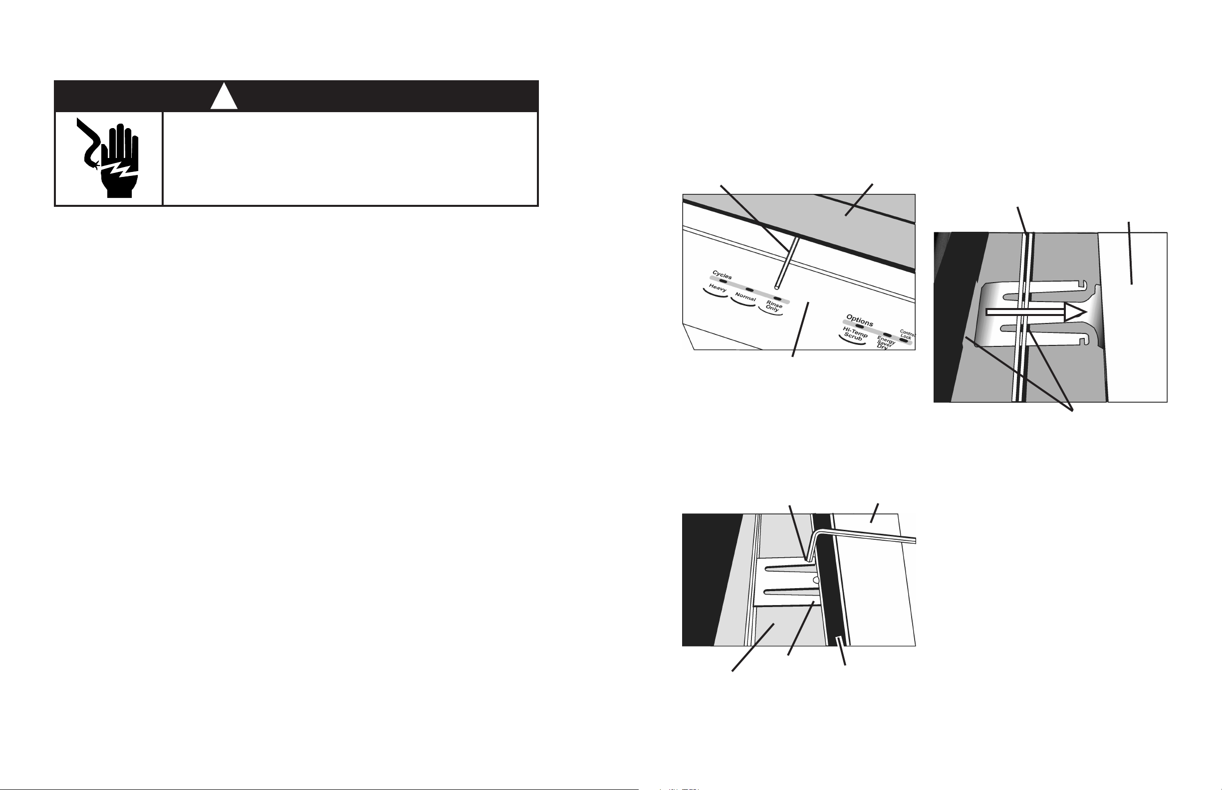
WHAT TO DO IF THE DISHWASHER DOOR DOES NOT OPEN
If the door latch assembly is damaged or malfunctions, the dishwasher door may not open. If this
occurs, the following procedure will open the dishwasher door and allow repairs to the door latch
assembly.
1. Insert an Allen wrench between the
countertop and the top of the console in
the vicinity of the door latch.
Allen Wrench
(Fig. 5-1)
Countertop
3. Open the door. The unsnapped latch
strike will remain attached to the door
catch and will be pulled out of the mount
ing slots in the support collar.
Cabinet Seal
Removed
(Fig. 5-3)
Top
of
Console
Console
Fig. 5-1
2. Turn the Allen wrench down and press
down on the latch strike retainer brackets
to release them from the support collar.
The latch strike retainer brackets are
snapped into the metal ridge on which
the cabinet seal is installed.
Press Here
(Fig. 5-2)
Top
of
Console
Mounting
Slots
Fig. 5-3
4. Remove the latch strike from the door latch
assembly.
5. Repair the door latch assembly.
6. Reinsert the latch strike into the slots in
the support collar and snap it into place.
(Fig. 3)
IV
Support
Collar
Press Here
Cabinet
Seal
Fig. 5-2
45
SECTION ONE
SPECIFICATIONS
ELECTRICAL SUPPLY: (Under Load) 60Hz, 120VAC
SUPPLY WATER FLOW RATE: (To Fill 2 Quarts (1.9 L) in 27 secs.) - 120psi Max., 20psi MIN.
SUPPLY WATER TEMPERATURE: 120° F to 160° F (49° C to 71° C)
WATER CHARGE: 1.8 Gal. (6.8 L) / First Fill
1.7 Gal. (6.5 L) / All Other Fills
LOWER SPRAY ARM ROTATION: 25 TO 40 RPM
UPPER SPRAY ARM ROTATION: 25 TO 35 RPM
APF DRAIN: .1 Gal. (.38 L) per 5 sec.
APF Pressure Switch Trip Point: 10 In. Water Column
HEATING ELEMENT HEATING RATE: 1°+ F Rise per Minute
WATER USAGE
Baked On Cookware Heavy, Normal
Soil Level
Sensed
High
Water
Usage
(gal/L)
8.8 -10.4/
33.4 -39.4
China - Light/China
Soil Level
Sensed
High
Water
Usage
(gal/L)
7.1-8.6/
26.9-32.5
INSTALLATION CONSIDERATIONS
GENERAL CONSIDERATIONS
For complete installation procedures see the “Installation Instructions” in the
literature packet provided with the dishwasher.
A video presentation,
4317280V, is available. This video covers the entire installation process.
Each location will present a different set of challenges that can be anticipated and solved before
installation begins.
• Check the planned location of the dishwasher.
• Easy access to hot water, drain line and electricity.
• Convenient access for loading. The dishwasher door should open and close freely.
• The opening under the counter should be square and the cabinet fronts should be perpendicular to the floor.
• Make sure the cabinet opening is free of intrusions such as braces or utility lines.
• Do not install the dishwasher on carpeted floors.
• An outside wall behind the dishwasher should be insulated to prevent the water line, inlet valve
and drain line from freezing and rupturing.
Key Features and Installation Considerations
, part number
Low
Quick Clean Up
First Fill
Water
Temp
Less
than
135° F
(57° C)
Greater
than
135° F
(57° C)
6.9/
26.2
Water
Usage
(gal/L)
6.9-8.4/
26.1-31.8
5.2-6.7/
19.7-25.4
Rinse Only
Low
Water
Usage
1.8-2.1/
6.9-7.9
5.5/
20.8
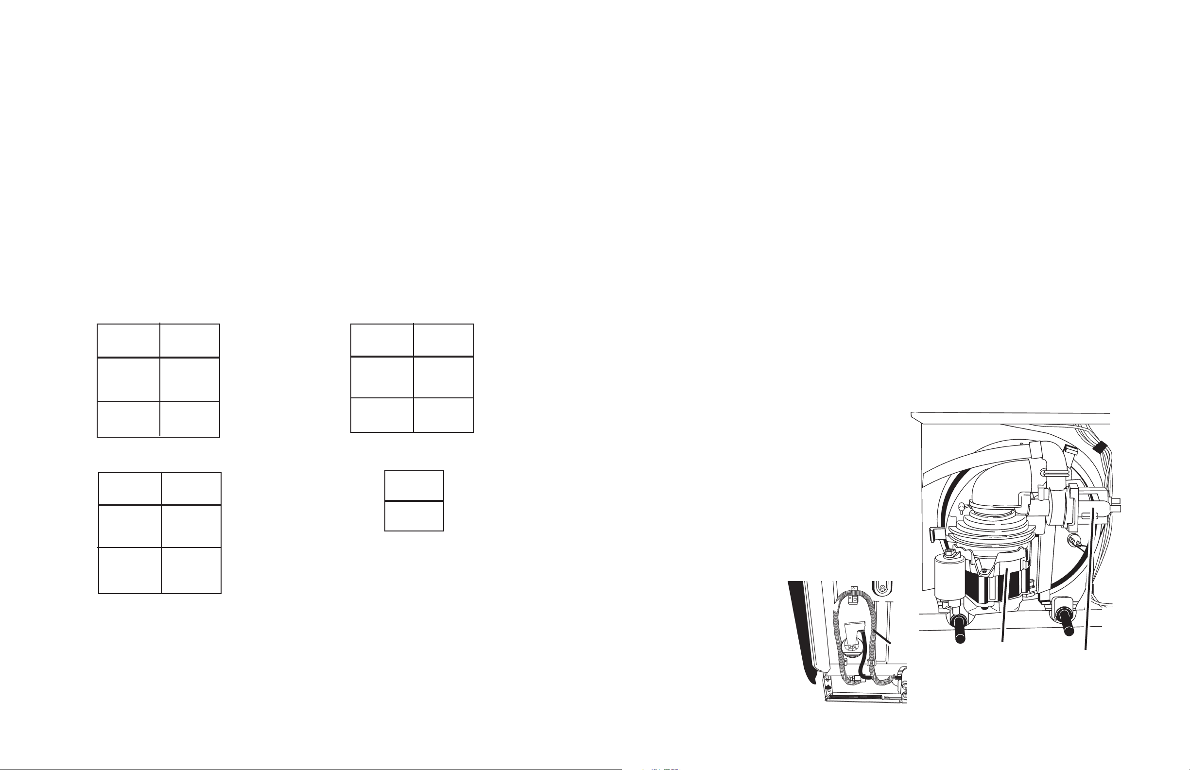
Additional Considerations
The application of a horizontal pump and filter
technology allows for the tub to be designed three
inches deeper than current models. This deeper
tub and longer door design will impact the installation process because there is less working
space available underneath the unit and correct
routing and placement of the drain hose, water
supply and electrical wiring is critical.
The tub must be level. Reduced water consumption of this dishwasher requires that it be installed
level and plumb for proper water recirculation back
into the sump area during operation.
Do not remove the drain
tube from the left side of
the tub. If the loop is
removed, the dishwasher
will not initiate Automatic
Purge Filtration. The drain
tube also contains a check
valve in the L-connector that
prevents backflow of water into
the dishwasher from the household drain system.
Drain Tube
Loop
Main Wash Motor
View of Sump Assembly from Underneath
Showing Horizontal Wash Pump Motor
and Drain Pump Motor
Drain Pump
Motor
44
1
-- NOTES --
MODEL SPECIFIC TABLES
MODEL
NO.
KUDS01DJ
KUDS01IJ
KUDR01TJ
KUDM01TJ
KUDI01TJ
MODEL
NO.
KUDS01DJ
KUDS01IJ
KUDR01TJ
KUDM01TJ
KUDI01TJ
USER
INTERFACE
8269200 (Top)
8269201 (Front)
8269199
8269198
8269197
8269196
PRESSURE
SWITCH
8268477
N/A
JUMPER
TAILS
8269202 8269207
N/A
INTERCONNECT
CARD
N/A
RINSE
DISPENSER
AID
SENSOR
8269189 8269190
8269996
N/A N/A
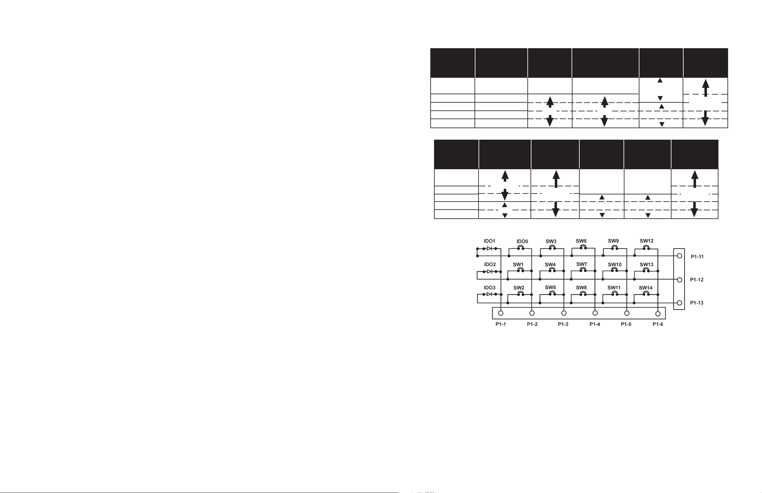
KEYPAD MATRIX
NUMERIC
DISPLAY
8269206
N/A
RINSE
AID
HARNESS
PUMP &
MOTOR
ASSMEBLY
8268422
WIRING
HARNESS
8269191
2
43
MODEL/SERIAL NUMBER PLATE
SECTION TWO
SERIAL NUMBER DESIGNATOR
SERIAL NUMBER
MANUFACTURING SITE
F = Findlay, OH
YEAR OF MANUFACTURE
K = 2000
WEEK OF MANUFACTURE
PRODUCT SEQUENCE NUMBER
F K 36 50001
MODEL NUMBER DESIGNATOR
MODEL NUMBER
INTERNATIONAL SALES OR
MARKETING CHANNEL
K = KITCHENAID BRAND
PRODUCT IDENTIFIER
PD = Convertable/Potable UD = Undercounter
FEATURE LEVEL: I, J, M, P, R, S
SERIES CONFIGURATION
UD JK01WHST 0
Model/Serial
Number Plate
(Left side of
frame behind
door)
THEORY OF OPERATION
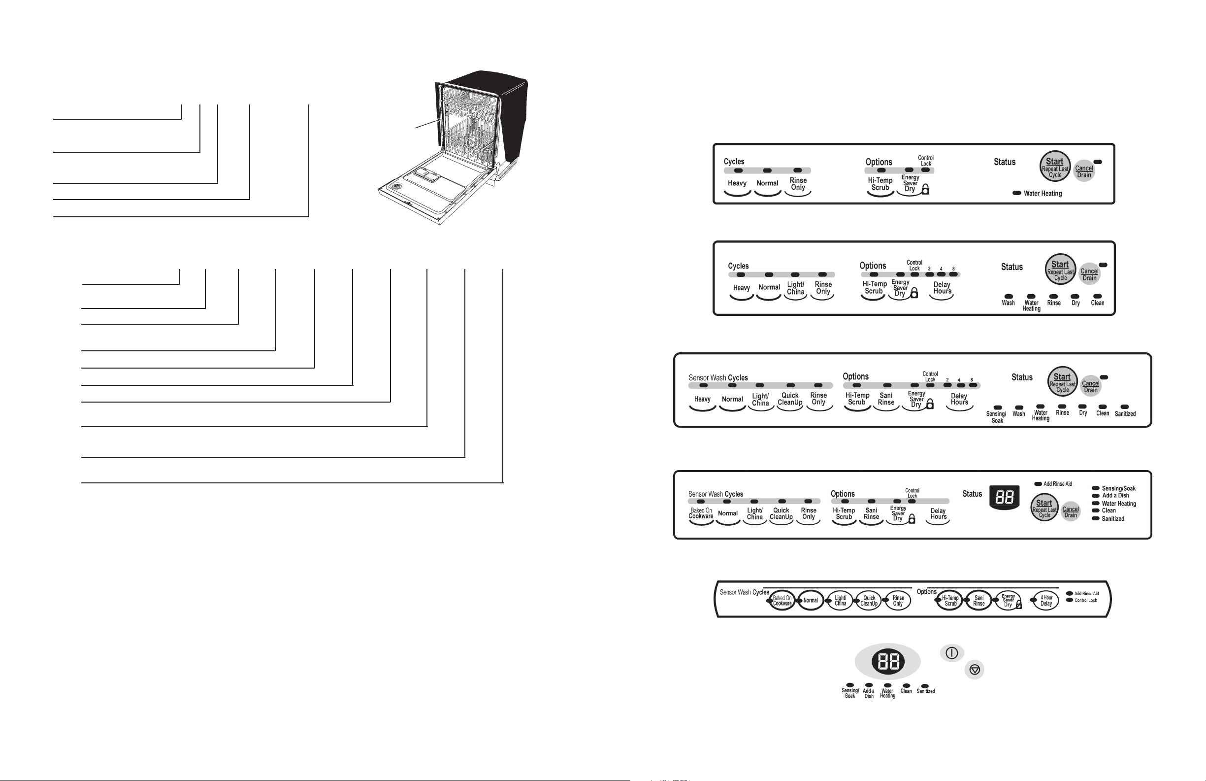
CONTROL PANELS
MODEL KUDI01TJ - 6” Console
MODEL KUDM01TJ - 6” Console
MODEL KUDR01TJ - 4” Console
FEATURES
YEAR OF INTRODUCTION
J = 2000
COLOR CODE
WH = White GR = Graphite BT = Biscuit
AL = Almond BL = Black
ENGINEERING CHANGE
0 = Basic Release; 1 = First Revision; 2 = Second Revision
MODEL KUDS01IJ - 4” Console
MODEL KUDS01DJ - 4” Split Console
TOP
42
FRONT
3
CYCLES AND CYCLE VARIATION
The KUD01 dishwasher optimizes washing performance and efficiently uses resources by varying
cycle functions and length. The selection of wash options allows the consumer to customize a cycle
for optimum washing performance. The soil sensor monitors soils in the wash water and sends input
to the electronic control. Generally, if the consumer does not choose a wash option, the electronic
control determines which cycle variation should be used.
In models without the soil sensor feature the electronic control automatically uses the Low Soil variation of the cycle unless the customer has chosen the High Temp Scrub option.
Wash Options
• The consumer’s selection of a High Temp Scrub wash option mandates a preset long version
of a wash cycle. The exception is the Normal cycle. If very little soils are present the electronic
control will use the Low Soil cycle variation with the High Temp Scrub option.
• The Sani Rinse option will mandate a higher final rinse temperature. This does not lengthen a
cycle except for the time spent in the thermal hold to raise the water temperature to the required 160° F.
• The Energy Saver Dry option merely turns off the heat during the drying function of the cycle.
Soil Sensing
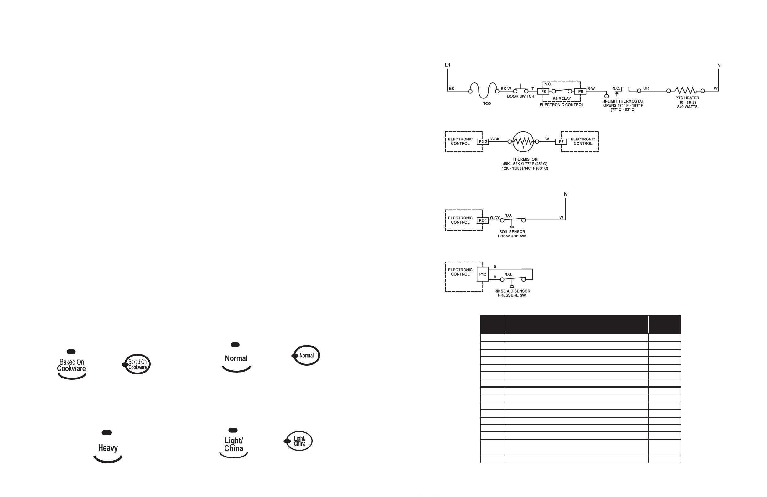
WATER HEATING
Heater Circuit
Thermistor
SOIL SENSING
* Resistance and
Wattage
Varies with Temperature
The Soil Sensor (pressure switch) monitors soil concentrations during wash functions and communicates this to the electronic control. If one or more soil sensor trips occur in the first washing interval
(interval “42”) of the Pre-Wash Period, the electronic control will use the High Soil version of the cycle.
If there are no trips and no options selected, the control uses the light soil version starting at interval
41. Soil sensor trips also invoke Automatic Purge Filtration (APF) events during the Pre-Wash and
Wash Periods. See APF description on page 5.
First Fill Water Temperature
The duration of the Quick Cleanup cycle may be modified based upon the water temperature of the
first fill. If the thermistor senses water temperature of 135°F or higher, the electronic control will eliminate the second wash function. The Quick Cleanup cycle is the only cycle in which this occurs.
Baked On Cookware
The most aggressive to virtually eliminate bacteria from the dish load. Use this cycle for hard-toclean, heavily soiled pots, pans, casseroles and
Normal
Use this cycle for loads with normal amounts of
food soil. (The energy-usage label is based on
this cycle.) Initial display time: 95 min.
regular tableware. Initial display time: 99 min.
Light/China
Heavy
Use this cycle for hard-to-clean, heavily soiled
pots, pans, casseroles and regular tableware.
Initial display time: 97 min.
Use this cycle for china and crystal. This cycle
uses a light wash and gentle dry. During heated
dry, the heating element cycles on and off. Initial
display time: 79 min.
RINSE AID SENSING
ELECTRONIC CONTROL CONNECTOR PINS
PIN
NO.
P1
P2-1
P2-2
P2-3
P2-4
P2-5
P2-6
P3
P4
P5
P6
P7
P8
P9
P10
P12
NOTE: Switch closes when significant soils accumulate in the pump.
NOTE: Switch closes when the Rinse Aid dispenser is empty.
DESCRIPTION
RIBBON CABLE TO USER INTERFACE
PRESSURE SWITCH (SOIL SENSE)
THERMISTOR
FILL VALVE
DISPENSER
OPEN
TO CONTROL POWER SUPPLY
DRAIN MOTOR
WASH MOTOR AUX WINDING
WASH MOTOR RUN WINDING
SWITCHED L1 TO HEATER
AC NEUTRAL
SWITCHED L1 FROM TCO
SWITCHED L1 TO WASH MOTOR COMMON
SWITCHED L1 TO VENT, FILL VALVE,
DISPENSER & PRESSURE SWITCH
OPTIONAL RINSE AID
WIRE
COLOR
-
O-GY
Y-BK
BR
LBU
O-BK
T
GY
Y
BU
W-R
W-V
T
R-BK
BU-BK
R
4
41
 Loading...