

KitchenAid KTRC22KVSS User Manual
REFRIGERATOR USER INSTRUCTIONS
THANK YOU for purchasing this high-quality product. If you should experience a problem not covered in TROUBLESHOOTING,
please visit our website at www.kitchenaid.com for additional information. If you still need assistance, call us at 1-800-422-1230.
In Canada, visit our website at www.kitchenaid.ca or call us at 1-800-807-6777.
You will need your model and serial number, located on the inside wall of the refrigerator compartment.
Table of Contents / Índice / Table des matières
REFRIGERATOR SAFETY.............................. 1
INSTALLATION INSTRUCTIONS .................. 2
REFRIGERATOR USE .................................. 10
REFRIGERATOR CARE................................ 11
TROUBLESHOOTING................................... 12
WATER FILTER CERTIFICATIONS .............14
PRODUCT DATA SHEETS ........................... 15
WARRANTY................................................... 17
REFRIGERATOR SAFETY
SEGURIDAD DEL REFRIGERADOR ........... 18
INSTRUCCIONES DE INSTALACIÓN ......... 19
USO DE SU REFRIGERADOR ..................... 28
CUIDADO DE SU REFRIGERADOR............ 30
SOLUCIÓN DE PROBLEMAS...................... 31
HOJA DE DATOS DEL PRODUCTO ........... 34
GARANTÍA..................................................... 36
SÉCURITÉ DU RÉFRIGÉRATEUR............... 37
INSTRUCTIONS D'INSTALLATION............. 38
UTILISATION DU RÉFRIGÉRATEUR .......... 47
ENTRETIEN DU RÉFRIGÉRATEUR ............ 49
DÉPANNAGE................................................. 50
FEUILLES DE DONNÉES
SUR LE PRODUIT......................................... 53
GARANTIE..................................................... 55
Your safety and the safety of others are very important.
We have provided many important safety messages in this manual and on your appliance. Always read and obey all safety
messages.
This is the safety alert symbol.
This symbol alerts you to potential hazards that can kill or hurt you and others.
All safety messages will follow the safety alert symbol and either the word “DANGER” or “WARNING.”
These words mean:
You can be killed or seriously injured if you don't immediately
DANGER
WARNING
All safety messages will tell you what the potential hazard is, tell you how to reduce the chance of injury, and tell you what can
happen if the instructions are not followed.
follow instructions.
can be killed or seriously injured if you don't
You
instructions.
follow
W10208837A
IMPORTANT SAFETY INSTRUCTIONS
To reduce the risk of fire, electric shock, or injury to persons when using the refrigerator, follow basic precautions,
WARNING:
including the following:
■
■
Plug into a grounded 3 prong outlet.
■
Do not remove ground prong.
■
Do not use an adapter.
■
Do not use an extension cord.
■
Disconnect power before servicing.
■
Replace all parts and panels before operating.
■
Remove doors from your old refrigerator.
Use nonflammable cleaner.
■
Keep flammable materials and vapors, such as gasoline,
away from refrigerator.
■
Use two or more people to move and install refrigerator.
■
Disconnect power before installing ice maker (on ice maker
kit ready models only).
SAVE THESE INSTRUCTIONS
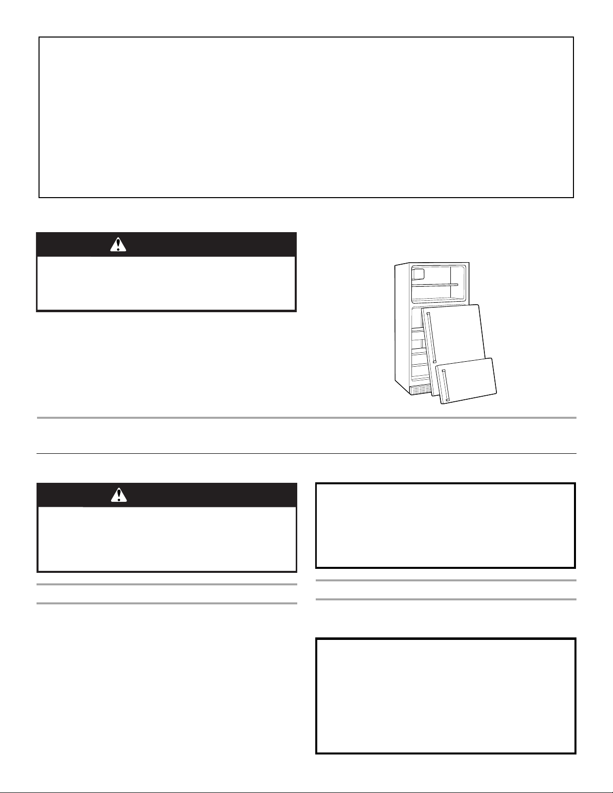
Proper Disposal of Your Old Refrigerator
WARNING
Suffocation Hazard
Remove doors from your old refrigerator.
Failure to do so can result in death or brain damage.
IMPORTANT: Child entrapment and suffocation are not problems
of the past. Junked or abandoned refrigerators are still dangerous
– even if they will sit for “just a few days.” If you are getting rid of
your old refrigerator, please follow these instructions to help
prevent accidents.
INSTALLATION INSTRUCTIONS
Unpack the Refrigerator
WARNING
Excessive Weight Hazard
Use two or more people to move and install
refrigerator.
Failure to do so can result in back or other injury.
Before You Throw Away Your Old Refrigerator or Freezer:
■ Take off the doors.
■ Leave the shelves in place so that children may not easily
climb inside.
When Moving Your Refrigerator:
Your refrigerator is heavy. When moving the refrigerator
for cleaning or service, be sure to protect the floor.
Always pull the refrigerator straight out when moving it.
Do not wiggle or “walk” the refrigerator when trying to move
it, as floor damage could occur.
Remove the Packaging
Do not use sharp instruments, rubbing alcohol, flammable fluids,
or abrasive cleaners to remove tape or glue. These products can
damage the surface of your refrigerator. For more information, see
“Refrigerator Safety.”
IMPORTANT: Do not remove the white foam air return insert from
behind the control panel on the ceiling of the refrigerator. If the
insert is removed, ice may migrate down from the freezer and
cause icicles to form.
2
Clean Before Using
After you remove all of the package materials, clean the inside of
your refrigerator before using it. See the cleaning instructions in
“Refrigerator Care.”
Important information to know about glass shelves
and covers:
Do not clean glass shelves or covers with warm water when
they are cold. Shelves and covers may break if exposed to
sudden temperature changes or impact, such as bumping.
Tempered glass is designed to shatter into many small,
pebble-size pieces. This is normal. Glass shelves and covers
are heavy. Use special care when removing them to avoid
impact from dropping.
Location Requirements
Electrical Requirements
WARNING
Explosion Hazard
Keep flammable materials and vapors, such as
gasoline, away from refrigerator.
Failure to do so can result in death, explosion, or fire.
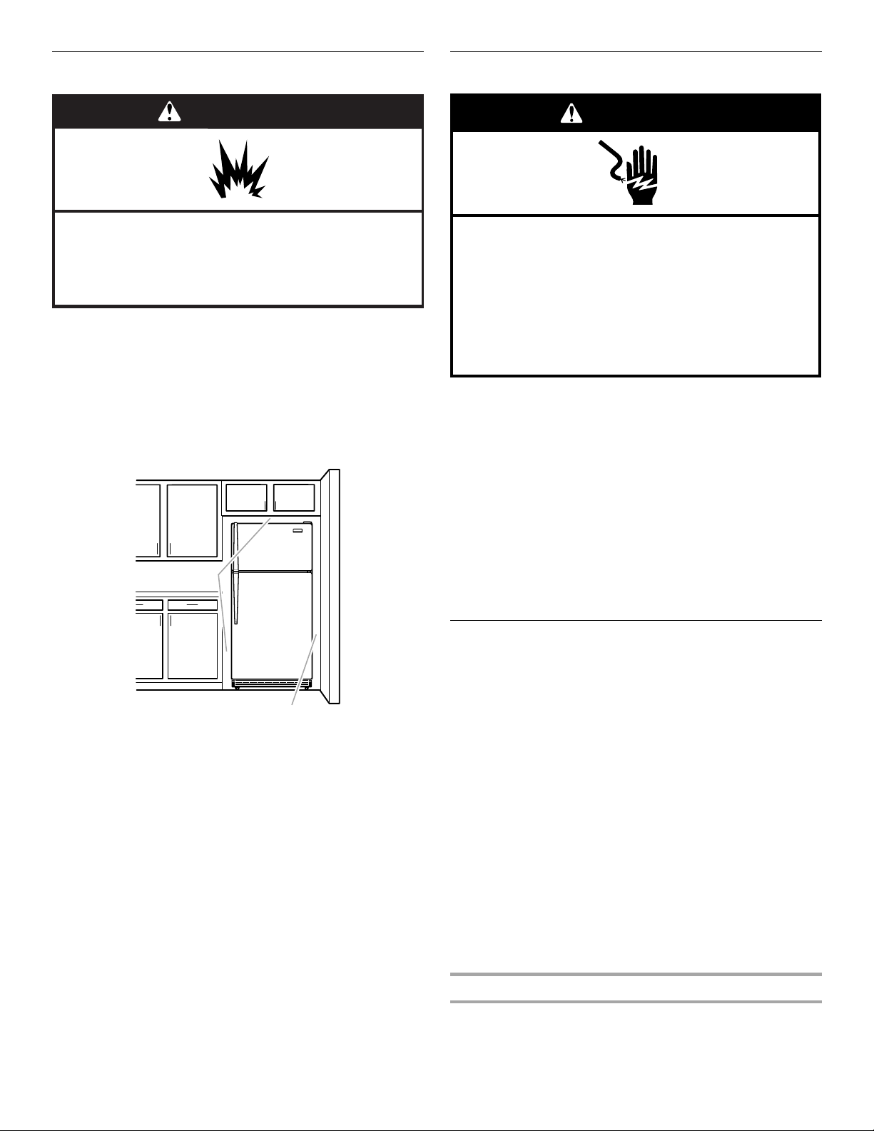
To ensure proper ventilation for your refrigerator, allow for a ½"
(1.25 cm) space on each side and at the top. When installing your
refrigerator next to a fixed wall, leave 2" (5.08 cm) minimum on the
hinge side (some models require more) to allow for the door to
swing open. If your refrigerator has an ice maker, allow extra
space at the back for the water line connections.
NOTE: It is recommended that you do not install the refrigerator
near an oven, radiator, or other heat source. Do not install the
refrigerator in a location where the temperature will fall below
55°F (13°C).
1
/
2" (1.25 cm)
WARNING
Electrical Shock Hazard
Plug into a grounded 3 prong outlet.
Do not remove ground prong.
Do not use an adapter.
Do not use an extension cord.
Failure to follow these instructions can result in death,
fire, or electrical shock.
Before you move your refrigerator into its final location, it is
important to make sure you have the proper electrical connection.
Recommended Grounding Method
A 115 Volt, 60 Hz., AC only, 15- or 20-amp fused, grounded
electrical supply is required. It is recommended that a separate
circuit serving only your refrigerator be provided. Use an outlet
that cannot be turned off by a switch. Do not use an
extension cord.
NOTE: Before performing any type of installation, cleaning, or
removing a light bulb, turn the control (Thermostat, Refrigerator or
Freezer Control depending on the model) to OFF and then
disconnect the refrigerator from the electrical source. When you
are finished, reconnect the refrigerator to the electrical source and
reset the control (Thermostat, Refrigerator or Freezer Control
depending on the model) to the desired setting. See “Using the
Controls.”
2" (5.08 cm)
Water Supply Requirements
Gather the required tools and parts before starting installation.
Read and follow the instructions provided with any tools listed
here.
TOOLS NEEDED:
■ Flat-blade screwdriver
■ ⁷⁄₁₆" (11.11 mm) and ¹⁄₂" (12.7 mm)
open-end or two adjustable
wrenches
NOTE: Your refrigerator dealer has a kit available with a ¹⁄₄"
(6.35 mm) saddle-type shutoff valve, a union, and copper tubing.
Before purchasing, make sure a saddle-type valve complies with
your local plumbing codes. Do not use a piercing-type or ³⁄₁₆"
(4.76 mm) saddle valve which reduces water flow and clogs more
easily.
IMPORTANT:
■ All installations must meet local plumbing code requirements.
■ Use copper tubing and check for leaks. Install copper tubing
only in areas where the household temperatures will remain
above freezing.
Water Pressure
A cold water supply with water pressure of between 30 and
120 psi (207 and 827 kPa) is required to operate the water
dispenser and ice maker. If you have questions about your water
pressure, call a licensed, qualified plumber.
■ ¹⁄₄" (6.35 mm) nut
driver
■ ¹⁄₄" (6.35 mm) drill bit
■ Cordless drill
3
Reverse Osmosis Water Supply
C
IMPORTANT: The pressure of the water supply coming out of a
reverse osmosis system going to the water inlet valve of the
refrigerator needs to be between 30 and 120 psi (207 and
827 kPa).
If a reverse osmosis water filtration system is connected to your
cold water supply, the water pressure to the reverse osmosis
system needs to be a minimum of 40 to 60 psi (276 to 414 kPa).
If the water pressure to the reverse osmosis system is less than
40 to 60 psi (276 to 414 kPa):
■ Check to see whether the sediment filter in the reverse
osmosis system is blocked. Replace the filter if necessary.
■ Allow the storage tank on the reverse osmosis system to refill
after heavy usage.
■ If your refrigerator has a water filter, it may further reduce the
water pressure when used in conjunction with a reverse
osmosis system. Remove the water filter. See “Water Filtration
System.”
If you have questions about your water pressure, call a licensed,
qualified plumber.
Connect the Water Supply
Read all directions before you begin.
IMPORTANT: If you turn the refrigerator on before the water line is
connected, turn the ice maker OFF.
Connect to Water Line
1. Unplug refrigerator or disconnect power.
2. Turn OFF main water supply. Turn ON nearest faucet long
enough to clear line of water.
3. Locate a ½" to 1¹⁄₄" (1.25 cm to 3.18 cm) vertical cold water
pipe near the refrigerator.
IMPORTANT:
■ Make sure it is a cold water pipe.
■ Horizontal pipe will work, but drill on the top side of the
pipe, not the bottom. This will help keep water away from
the drill and normal sediment from collecting in the valve.
4. Determine the length of copper tubing you need. Measure
from the connection on the lower left rear of refrigerator to the
water pipe. Add 7 ft. (2.1 m) to allow for cleaning. Use ¹⁄₄"
(6.35 mm) O.D. (outside diameter) copper tubing. Be sure both
ends of copper tubing are cut square.
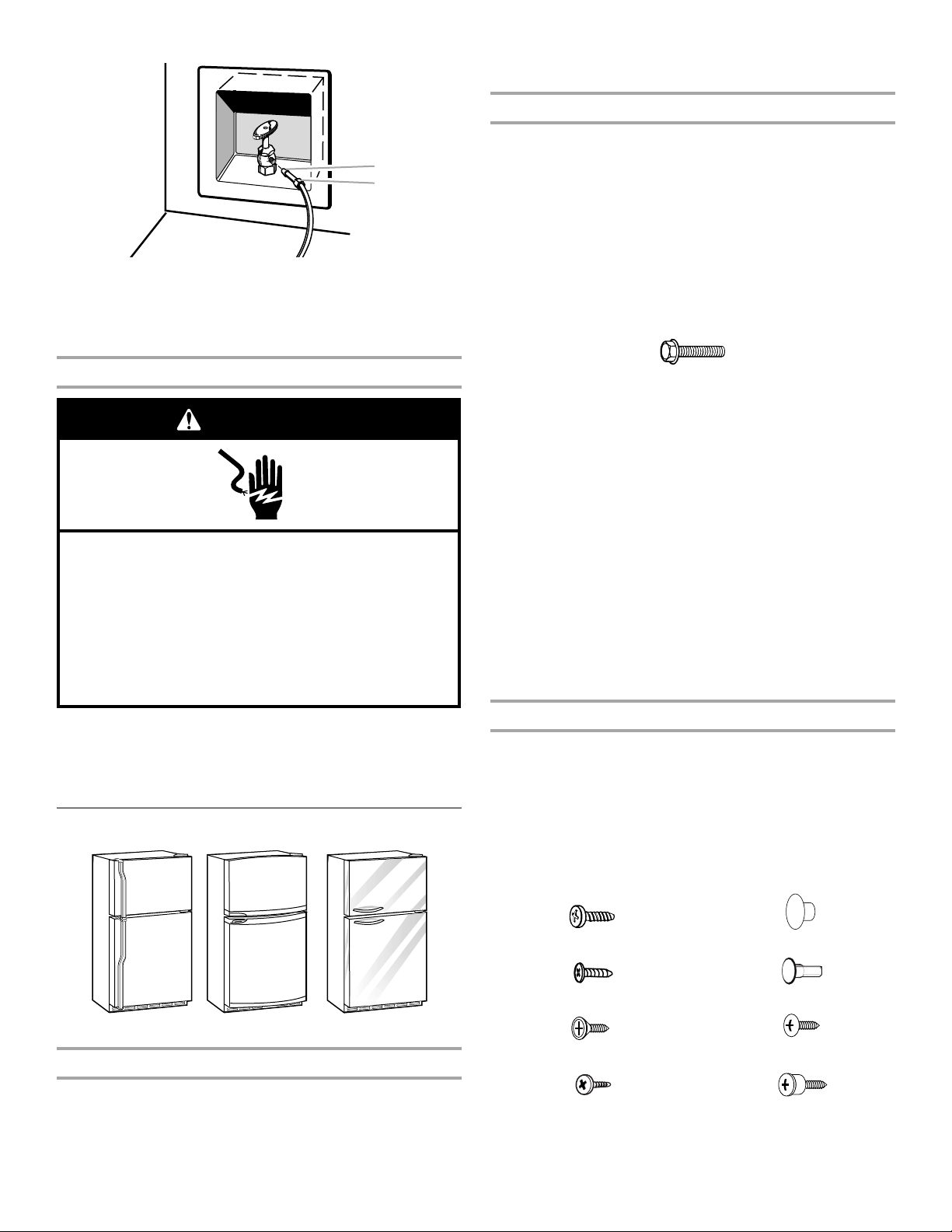
5. Using a cordless drill, drill a ¹⁄₄" hole in the cold water pipe you
have selected.
8. Place the free end of the tubing in a container or sink, and turn
ON the main water supply. Flush the tubing until water is clear.
Turn OFF the shutoff valve on the water pipe. Coil the copper
tubing.
Connect to Refrigerator
Style 1
1. Unplug refrigerator or disconnect power.
2. Attach the copper tube to the valve inlet using a compression
nut and sleeve as shown. Tighten the compression nut. Do not
overtighten.
3. Use the tube clamp on the back of the refrigerator to secure
the tubing to the refrigerator as shown. This will help avoid
damage to the tubing when the refrigerator is pushed back
against the wall.
4. Turn shutoff valve ON.
5. Check for leaks. Tighten any connections (including
connections at the valve) or nuts that leak.
A
B
D
E
A. Tube clamp
B. Tube clamp screw
C. Copper tubing
D. Compression nut
E. Valve inlet
6. The ice maker is equipped with a built-in water strainer. If your
water conditions require a second water strainer, install it in
the ¹⁄₄" (6.35 mm) water line at either tube connection. Obtain
a water strainer from your nearest appliance dealer.
Style 2
1. Unplug refrigerator or disconnect power.
2. Remove and discard the black nylon plug from the gray water
tube on the rear of the refrigerator.
3. If the gray water tube supplied with the refrigerator is not long
enough, a ¹⁄₄" x ¹⁄₄" (6.35 mm x 6.35 mm) coupling is needed in
order to connect the water tubing to an existing household
water line. Thread the provided nut onto the coupling on the
end of the copper tubing.
NOTE: Tighten the nut by hand. Then tighten it with a wrench
two more turns. Do not overtighten.
A
G
B
C
DEF
A. Cold water pipe
B. Pipe clamp
C. Copper tubing
D. Compression nut
E. Compression sleeve
F. Shutoff valve
G. Packing nut
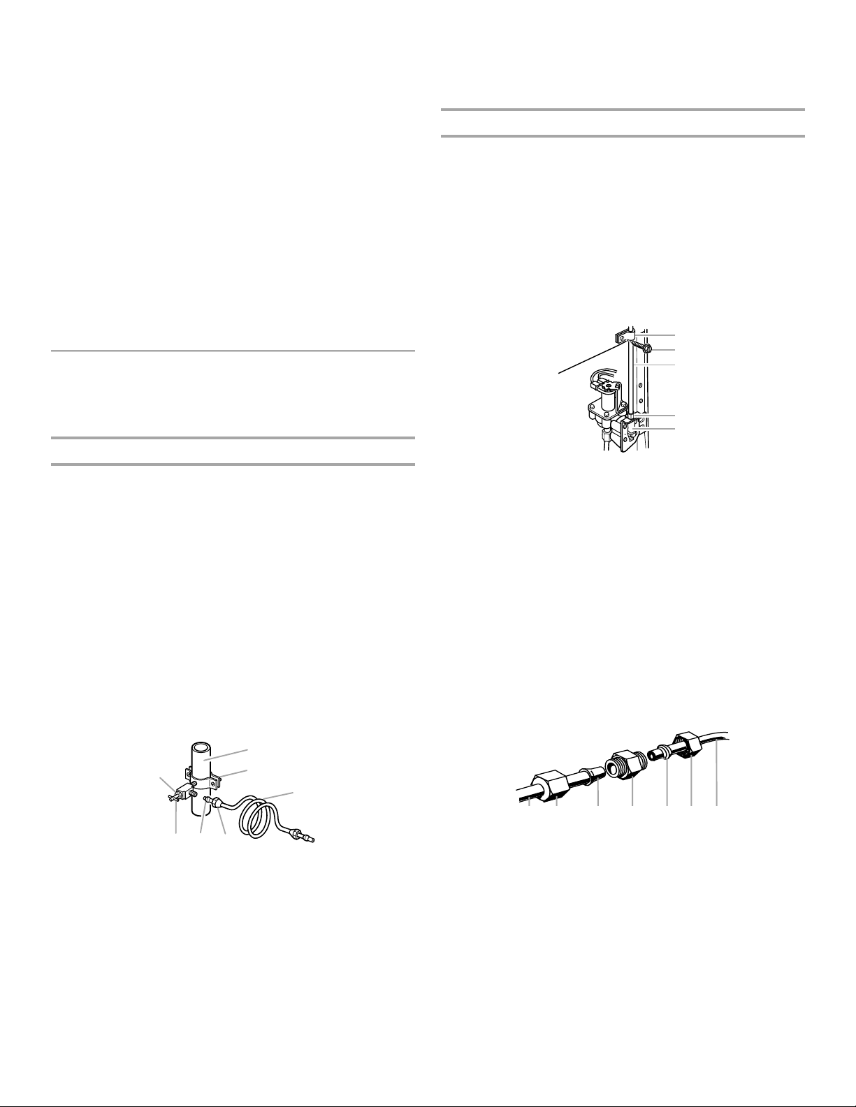
6. Fasten the shutoff valve to the cold water pipe with the pipe
clamp. Be sure the outlet end is solidly in the ¹⁄₄" (6.35 mm)
drilled hole in the water pipe and that the washer is under the
pipe clamp. Tighten the packing nut. Tighten the pipe clamp
screws slowly and evenly so washer makes a watertight seal.
Do not overtighten or you may crush the copper tubing.
7. Slip the compression sleeve and compression nut onto the
copper tubing as shown. Insert the end of the tubing into the
outlet end squarely as far as it will go. Screw compression nut
onto outlet end with adjustable wrench. Do not overtighten.
4
A B C D E F G
A. Refrigerator water tubing
B. Nut (provided)
C. Bulb
D. Coupling (provided)
E. Ferrule (purchased)
F. N u t ( pu rc ha s ed )
G.Household water line
4. Turn shutoff valve ON.
5. Check for leaks. Tighten any nuts or connections (including
connections at the valve) that leak.
Style 3
1. Unplug refrigerator or disconnect power.
2. Remove and discard the black nylon plug from the gray water
tube on the rear of the refrigerator.
3. Thread the provided nut onto the water valve as shown.
NOTE: Tighten the nut by hand. Then tighten it with a wrench
two more turns. Do not overtighten.
A. Bulb
A
B
w
B. Nut (provided)
4. Turn shutoff valve ON.
5. Check for leaks. Tighten any nuts or connections (including
connections at the valve) that leak.
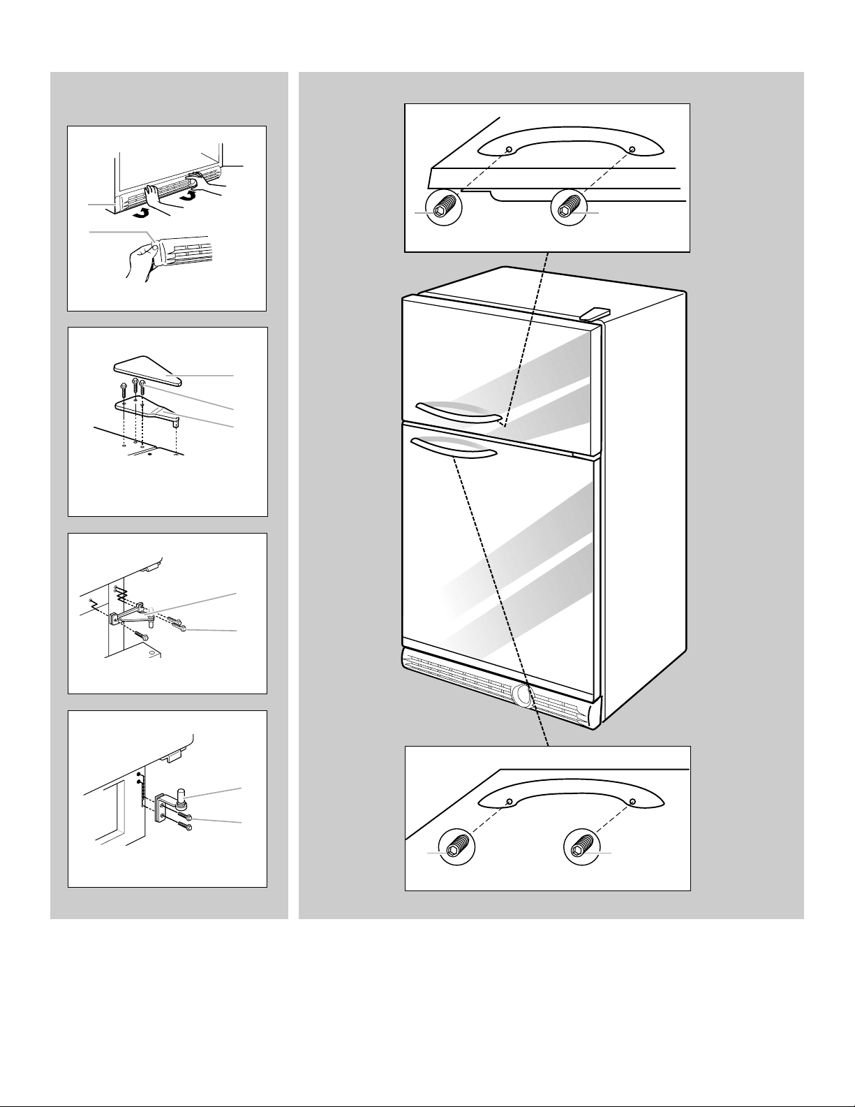
2. Pull handle straight out from the door. Make sure you keep
screws for reattaching handles.
Remove Doors and Hinges (all models)
IMPORTANT:
■ Unplug refrigerator or disconnect power.
■ Remove food and any adjustable door or utility bins from
doors.
■ If you are only removing and replacing the doors, the
instructions are the same regardless of door style.
■ If you have a standard or contour door and are also going to
reverse the door swing, follow the instructions for the
appropriate door style.
■ All graphics referenced in the following instructions are
included later in this section after “Final Steps.”
Complete the Installation
WARNING
Electrical Shock Hazard
Plug into a grounded 3 prong outlet.
Do not remove ground prong.
Do not use an adapter.
Do not use an extension cord.
Failure to follow these instructions can result in death,
fire, or electrical shock.
1. Plug into a grounded 3 prong outlet.
2. Flush the water system. See “Water Dispenser.”
NOTE: Allow 24 hours to produce the first batch of ice. Discard
the first three batches of ice produced. Allow 3 days to completely
fill ice container.
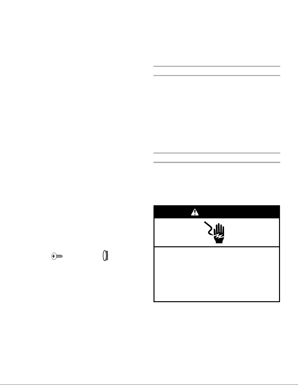
Refrigerator Doors
⁵⁄₁₆" Hex-Head Hinge Screw
TOOLS NEEDED: ⁵⁄₁₆" hex-head socket wrench, #2 Phillips
screwdriver, flat-blade screwdriver, ⁵⁄₁₆" open-end wrench, flat 2"
putty knife.
1. Unplug refrigerator or disconnect power.
2. Open refrigerator door and remove base grille from the bottom
front of the refrigerator. See Base Grille graphic.
3. Close the refrigerator door and keep both doors closed until
you are ready to lift them free from the cabinet.
NOTE: Provide additional support for the doors while the
hinges are being moved. Do not depend on the door magnets
to hold the doors in place while you are working.
4. Remove the parts for the top hinge as shown in Top Hinge
graphic. Lift the freezer door free from the cabinet.
5. Remove the parts for the center hinge as shown in the Center
Hinge graphic. Lift the refrigerator door free from the cabinet.
6. Remove the parts for the bottom hinge as shown in the
Bottom Hinge graphic.
Reverse Doors (optional on some models)
IMPORTANT:
■ Architect
■ If you want to reverse your standard or contour doors so they
open from the opposite side, follow these steps. If you are not
reversing the doors, see “Replace Doors and Hinges” later in
this section.
®
Series doors with curved handle are not reversible.
Standard Door
Graphics are included later in this section.
Standard Contour
Architect
®
Series
Remove Handle (Architect® Series)
Graphics are included later in this section.
NOTE: These instructions are for the Architect® Series doors with
curved handle only.
1. Using a ¹⁄₈" Allen wrench, loosen the two setscrews located
underneath each handle.
Door Stop Screw
Door Handle Sealing Screw
Flat-Head Handle Screw
Door Handle Seal Screw Front
Door Hinge Hole Plug
Cabinet Hinge Hole Plug
Round-Head Handle Scre
Shoulder Handle Screw
5
Cabinet
1. Remove ⁵⁄₁₆" hex-head hinge screws from handle side and
move them to opposite side. See Graphic 1-1.
2. Remove cabinet hinge hole plugs from cabinet top and move
them to opposite side hinge holes as shown. See
Graphic 1-2.
Freezer door
1. Remove freezer handle assembly as shown. Keep all parts
together. See Graphic 2.
2. Remove door hinge hole plug. Move to opposite side as
shown. See Graphic 3.
3. Remove door handle sealing screws. Move to opposite side of
freezer door as shown. See Graphic 4.
4. Remove door stop. Move to opposite side of freezer door as
shown. See Graphic 5.
5. Position handle on opposite side of freezer door. Assemble
handles on door as shown. See Graphic 2.
6. Tighten all screws. Set aside door until hinges and refrigerator
compartment door are in place.
Refrigerator door
1. Remove the handle screw cover. Depending on your model,
see Graphic 6-1 or 6-2.
2. Remove the handle screws. Keep all parts together. See
Graphic 6-3.
3. Remove door hinge hole plug from the refrigerator door. Move
to the opposite side hinge hole as shown. See Graphic 3.
4. Remove the door handle sealing screws. Move to opposite
side of the refrigerator door. See Graphic 4.
5. Remove door handle seal screw front. Move to opposite side
of refrigerator door as shown. See Graphic 7.
6. Remove door stop. Move to opposite side of refrigerator door
as shown. See Graphic 5.
7. Position the refrigerator handle on the opposite side of the
refrigerator door. Drive the two top screws. Then, align the
lower portion of handle and drive the bottom screw. See
Graphic 6-3.
8. Tighten all screws.
9. Replace the screw cover. Depending on your model, see
Graphic 6-1 or 6-2.
10. Set aside the refrigerator door until the bottom hinge is
installed on the product.
3. Remove freezer handle assembly as shown. Keep all parts
together. See Graphic 4.
4. Remove refrigerator handle assembly as shown. Keep all
parts together. See Graphic 5.
5. Rotate and position handle from refrigerator door onto freezer
door and assemble as shown in Graphic 6.
6. Rotate and position handle from freezer door onto refrigerator
door and assemble as shown in Graphic 7.
7. Reinstall door stops to opposite side. See Graphic 8.
Replace Doors and Hinges
NOTE: Graphic may be reversed if door swing is reversed.
1. Replace the parts for the bottom hinge as shown and tighten
screws. See Bottom Hinge graphic. Replace the refrigerator
door.
NOTE: Provide additional support for the doors while the
hinges are being moved. Do not depend on the door magnets
to hold the doors in place while you are working.
2. Assemble the parts for the center hinge as shown and tighten
all screws. See Center Hinge graphic. Replace the freezer
door.
3. Assemble the parts for the top hinge as shown in Top Hinge
graphic. Do not tighten screws completely.
4. Line up the doors so that the bottom of the freezer door aligns
evenly with the top of the refrigerator door. Tighten all screws.
Final Steps
1. Check all holes to make sure that hole plugs and screws are in
place. Reinstall top hinge cover. See Top Hinge graphic.
NOTE: On the left-hand side of the base grille there is a
removable tab which is a bottom hinge hole plug. Break off
the tab from the base grille and insert the bottom hinge hole
plug into the bottom hinge holes. See Base Grille graphic.
2. Replace the base grille. See Base Grille graphic.
WARNING
Contour Door
Graphics are included later in this section.
Round-Head
Handle Screw
Cabinet
1. Remove
move them to opposite side. See Graphic 1-1.
2. Remove cabinet hinge hole plugs from the cabinet top and
move them to opposite side hinge holes as shown in
Graphic 1-2.
Doors
1. Remove door hinge hole plug from top of freezer door. Move
to opposite side as shown in Graphic 2.
2. Remove door stop from both the freezer and refrigerator door.
See Graphic 3.
NOTE: When reversing the door, the freezer handle becomes the
refrigerator door handle and the refrigerator door handle becomes
the freezer handle. See Door Handle Reversal graphic.
⁵⁄₁₆" hex-head hinge screws from handle side and
Door Handle
Screw Hole Plug
6
Electrical Shock Hazard
Plug into a grounded 3 prong outlet.
Do not remove ground prong.
Do not use an adapter.
Do not use an extension cord.
Failure to follow these instructions can result in death,
fire, or electrical shock.
3. Plug into a grounded 3 prong outlet.
4. Return all removable door parts to the doors and food to the
product.
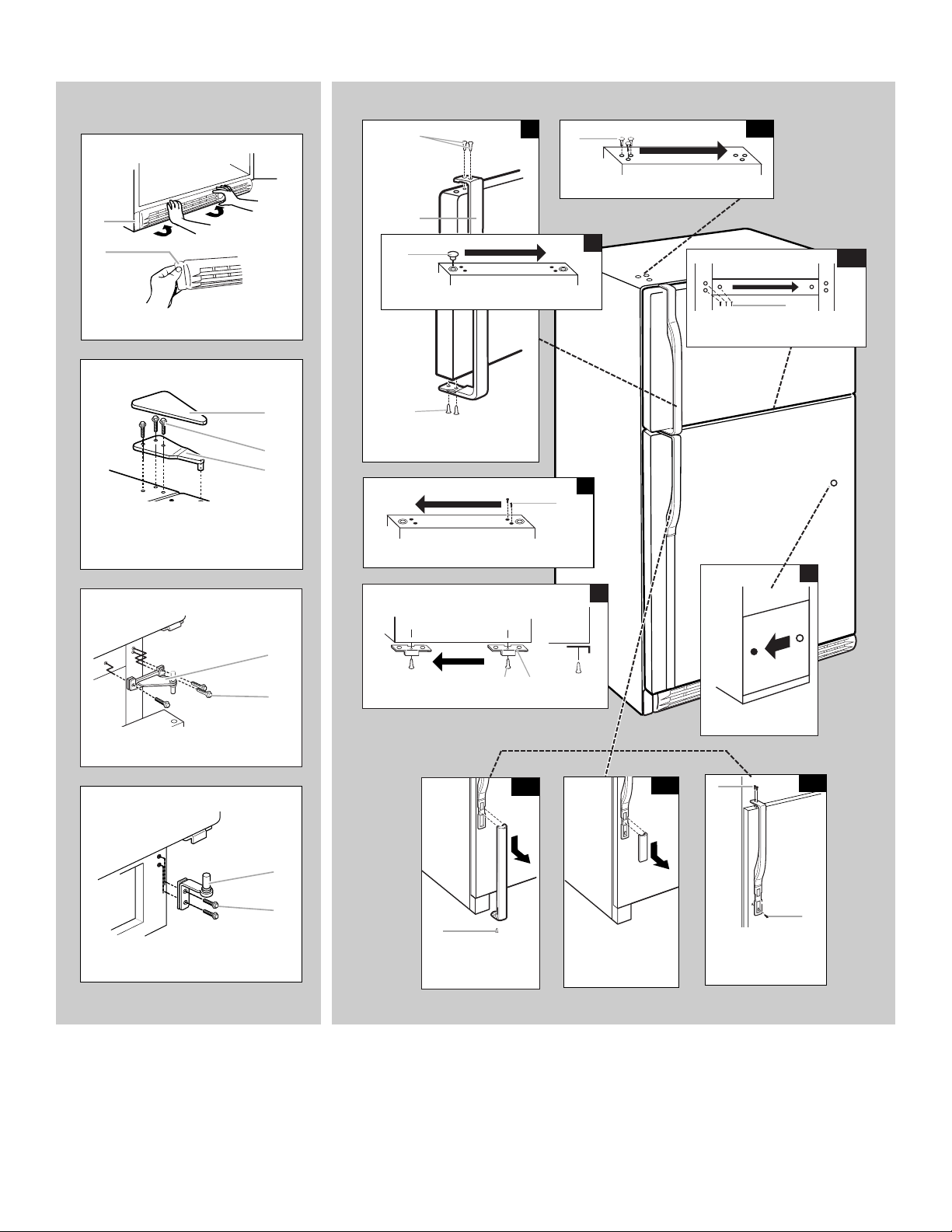
Standard
Door Removal &
Replacement
Base Grille
A
A
A. Bottom Hinge Hole Plug
Top Hinge
A. Top Hinge Cover
B. ⁵⁄₁₆" Hex-Head Hinge Screws
C. Top Hinge
Center Hinge
Door Swing Reversal (optional)
A
2
A
A. Cabinet Hinge Hole Plugs
B
A
3
A. Door Hinge Hole Plug
A
. ⁵⁄₁₆"
A
A
A. Flat-Head Handle Screws
B
C
B. Freezer Door Handle
4
A
A. Door Handle Sealing Screws
Front View
Side View
5
1-2
1-1
A
1
Hex-Head Hinge Screws
7
A. Center Hinge
B. ⁵⁄₁₆" Hex-Head Hinge Screws
Bottom Hinge
A. Bottom Hinge
B. ⁵⁄₁₆" Hex-Head Hinge Screws
A
A. Door Stop Screw
B
A
B
B. Door Stop
A
A. Shoulder
Handle Screw
B
A
A. Door Handle
Seal Screw Front
6-1
6-2
A
A. Flat-Head
Handle Screw
B. Round-Head
Handle Screw
6-3
B
7

Contour
Door Removal &
Replacement
Base Grille
A
A
A. Bottom Hinge Hole Plug
Top Hinge
A. Top Hinge Cover
B. ⁵⁄₁₆" Hex-Head Hinge Screws
C. Top Hinge
Center Hinge
Door Swing Reversal (optional)
1-1
A
A.
⁵⁄₁₆"
Hex-Head Hinge Screws
A
B
C
Door Handle Reversal
1-2
A
A. Cabinet Hinge Hole Plugs
2
A
A. Door Hinge Hole Plug
3
Removal of Door Stops
A. Door Stop
B. Door Stop Screw
4
Freezer Door
A
B
A. Door Handle Sealing Screws
B. Door Handle Screw Hole Plugs
A
B
A. Center Hinge
B. ⁵⁄₁₆" Hex-Head Hinge Screws
Bottom Hinge
A. Bottom Hinge
B. ⁵⁄₁₆" Hex-Head Hinge Screws
A
B
A
B
8
Reinstallation of Door Stops
B
A
A. Door Stop
B. Door Stop Screw
5
6
7
Refrigerator Door
A
B
A. Door Handle Screw Hole Plugs
B. Door Handle Sealing Screws
Freezer Door
A
B
A. Door Handle Sealing Screws
B. Door Handle Screw Hole Plugs
Refrigerator Door
A
B
A. Door Handle Screw Hole Plugs
B. Door Handle Sealing Screws
8
Architect
®
Series
Door Removal &
Replacement
Base Grille
A
A
A. Bottom Hinge Hole Plug
Top Hinge
A. Top Hinge Cover
5
/
16
B. " Hex-Head Hinge Screws
C. Top Hinge
Door Handle Removal
A
A. 1/8" Setscrew
A
B
C
A
Center Hinge
A. Center Hinge
5
/
16
B. " Hex-Head Hinge Screws
Bottom Hinge
A. Bottom Hinge
5
/
B. " Hex-Head Hinge Screws
16
A
B
A
B
A
1
A.
/8" Setscrew
A
9

Adjust the Doors
Door Closing
Your refrigerator has two front adjustable rollers – one on the right
and one on the left. If your refrigerator seems unsteady or you
want the doors to close easier, adjust the refrigerator's tilt using
the instructions below.
1. Remove the base grille. See the Base Grille graphic in
“Refrigerator Doors.” The two leveling screws are part of the
front roller assemblies which are at the base of the refrigerator
on either side.
2. Use a screwdriver to adjust the leveling screws. Turn the
leveling screw to the right to raise that side of the refrigerator
or turn the leveling screw to the left to lower that side. It may
take several turns of the leveling screws to adjust the tilt of the
refrigerator.
NOTE: Having someone push against the top of the
refrigerator takes some weight off the leveling screws and
rollers. This makes it easier to adjust the screws.
3. Open both doors again to make sure that they close as easily
as you like. If not, tilt the refrigerator slightly more to the rear
by turning both leveling screws to the right. It may take several
more turns, and you should turn both leveling screws the
same amount.
4. Replace the base grille.
Align Doors
Mid-setting “3”
IMPORTANT:
■ Give your refrigerator time to cool down completely before
adding food. It is best to wait 24 hours before you put food
into the refrigerator.
■ If you add food before the refrigerator has cooled completely,
your food may spoil. Adjusting the Refrigerator and Freezer
Controls to a higher (colder) than recommended setting will
not cool the compartments any faster.
Adjusting Controls
The mid-settings indicated in the previous section should be
correct for normal household usage. The controls are set correctly
when milk or juice is as cold as you like and when ice cream is
firm.
If the temperature is too warm or too cold in the refrigerator or
freezer, first check the air vents to be sure they are not blocked.
If you need to adjust temperatures, use the settings listed in the
chart below as a guide. On models with two controls, adjust the
refrigerator temperature first. Wait at least 24 hours between
adjustments and then recheck the temperatures.
CONDITION/REASON: ADJUSTMENT:
REFRIGERATOR too warm REFRIGERATOR or
FREEZER too warm/too
little ice
TEMPERATURE Control one
setting higher
FREEZER or TEMPERATURE
Control one setting higher
MAX ice production switch
If the space between your doors looks uneven, you can adjust it
using the instructions below:
1. Pry off the top hinge cover.
2. Loosen the top hinge screws using a ⁵⁄₁₆" socket or wrench.
3. Have someone hold the door in place or put a spacer between
the doors while you tighten the top hinge screws.
4. Replace the top hinge cover.
REFRIGERATOR USE
Using the Controls
For your convenience, your refrigerator controls are preset at the
factory. When you first install your refrigerator, make sure that the
controls are still preset to the mid-settings as shown.
NOTE: To turn your refrigerator off, turn the refrigerator control to
the word OFF or until the word OFF appears. Your product will not
cool when the refrigerator control is set to OFF.
Mid-setting “3”
REFRIGERATOR too cold REFRIGERATOR or
TEMPERATURE Control one
setting lower
FREEZER too cold FREEZER or TEMPERATURE
Control one setting lower
Crisper Humidity Control
(on some models)
You can control the amount of humidity in the moisture-sealed
crisper. Adjust the control to any setting between LOW and HIGH.
LOW (open) for best storage of fruits and vegetables with skins.
HIGH (closed) for best storage of fresh, leafy vegetables.
Ice Maker
Turning the Ice Maker On/Off
To turn the ice maker ON, simply lower the wire shutoff arm.
To manually turn the ice maker OFF, lift the wire shutoff arm to the
OFF (arm up) position and listen for the click.
10

NOTE: Your ice maker has an automatic shutoff. As ice is made,
the ice cubes will fill the ice storage bin and the ice cubes will
raise the wire shutoff arm to the OFF (arm up) position. Do not
force the wire shutoff arm up or down.
OptimIce
NORMAL
Ice Production Rate
■ Allow 24 hours to produce the first batch of ice. Discard the
first three batches of ice produced.
■ The ice maker should produce approximately 8 to 12 batches
of ice in a 24-hour period.
■ To increase ice production, lower the freezer and refrigerator
temperature. See “Using the Controls.” Wait 24 hours
between adjustments.
■ For maximum ice production (on some models), push the
switch to OptimIce. The ice maker should produce 16 to
20 batches of ice in a 24-hour period in the OptimIce mode.
Remember
■ The quality of your ice will be only as good as the quality of the
water supplied to your ice maker. Avoid connecting the ice
maker to a softened water supply. Water softener chemicals
(such as salt) can damage parts of the ice maker and lead to
poor quality ice. If a softened water supply cannot be avoided,
make sure the water softener is operating properly and is well
maintained.
■ Do not use anything sharp to break up the ice in the bin. This
can cause damage to the ice container and the dispenser
mechanism.
■ Do not store anything on top of or in the ice maker or ice bin.
Water Dispenser
IMPORTANT:
■ After connecting the refrigerator to a water source, flush the
water system. Use a sturdy container to depress and hold the
water dispenser lever for 5 seconds, then release it for
5 seconds. Repeat until water begins to flow. Once water
begins to flow, continue depressing and releasing the
dispenser lever (5 seconds on, 5 seconds off) for an additional
2 minutes. This will flush air from the filter and water
dispensing system. Additional flushing may be required in
some households. As air is cleared from the system, water
may spurt out of the dispenser.
■ Allow several hours for the refrigerator to cool down and chill
water.
■ Dispense enough water every week to maintain a fresh supply.
Water Filtration System
Do not use with water that is microbiologically unsafe or
of unknown quality without adequate disinfection before
or after the system. Systems certified for cyst reduction
may be used on disinfected waters that may contain
filterable cysts.
Water Filter Status Light (on some models)
The water filter status light will help you know when to change
your water filter. The light will change from green to yellow. This
tells you that it is almost time to change the filter. It is
recommended that you replace the water filter when the status
light changes to red OR water flow to your water dispenser or ice
maker decreases noticeably. The filter should be replaced at least
every 6 months depending on your water quality and usage.
After changing the water filter, reset the water filter status light.
The status light will change from red to green when the system is
reset.
Non-Indicator Water Filter (on some models)
If your refrigerator does not have the water filter status light, you
should change the water filter cartridge at least every 6 months
depending on your water quality and usage. If the water flow to
the water dispenser or ice maker decreases noticeably before
6 months have passed, replace the water filter more often.
Using the Dispenser Without the Water Filter
You can run the dispenser without a water filter. Your water will not
be filtered.
1. Remove the water filter.
2. Slide the cap off the end of the filter and replace the cap in the
base grille.
IMPORTANT: Do not discard the cap. It is part of your
refrigerator. Keep the cap to use with the replacement filter.
REFRIGERATOR CARE
Cleaning
WARNING
Explosion Hazard
Use nonflammable cleaner.
Failure to do so can result in death, explosion, or fire.
To Dispense Water:
There are two water dispenser buttons for use with different sizes
of containers.
1. Press a sturdy glass against the back button or hold a
container under the dispenser while pressing the front button.
2. Remove the glass or release the front button to stop
dispensing.
Both the refrigerator and freezer sections defrost automatically.
However, clean both sections about once a month to avoid
buildup of odors. Wipe up spills immediately.
IMPORTANT:
■ Because air circulates between both sections, any odors
formed in one section will transfer to the other. You must
thoroughly clean both sections to eliminate odors. To avoid
odor transfer and drying out of food, wrap or cover foods
tightly.
11
■ For stainless steel models, stainless steel is corrosion-
WARMER
COOLER
RECOMMENDED SETTING
REFRIGERATOR
WARMER
COOLER
RECOMMENDED SETTING
FREEZER
ALLOW 24 HOURS BETWEEN ADJUSTMENTS
resistant and not corrosion-proof. To help avoid corrosion of
your stainless steel, keep your surfaces clean by using the
following cleaning instructions.
To Clean Your Refrigerator:
NOTE: Do not use abrasive or harsh cleaners such as window
sprays, scouring cleansers, flammable fluids, muriatic acid,
cleaning waxes, concentrated detergents, bleaches or cleansers
containing petroleum products on exterior surfaces (doors and
cabinet), plastic parts, interior and door liners or gaskets. Do not
use paper towels, scouring pads, or other harsh cleaning tools.
1. Unplug refrigerator or disconnect power.
2. Hand wash, rinse, and dry removable parts and interior
surfaces thoroughly. Use a clean sponge or soft cloth and a
mild detergent in warm water.
3. Clean the exterior surfaces.
Painted metal: Wash painted metal exteriors with a clean,
soft cloth or sponge and a mild detergent in warm water.
Rinse surfaces with clean, warm water and dry immediately to
avoid water spots.
Stainless steel: Wash stainless steel surfaces with a clean,
soft cloth or sponge and a mild detergent in warm water.
Rinse surfaces with clean, warm water and dry immediately to
avoid water spots.
NOTE: When cleaning stainless steel, always wipe with the
grain to avoid cross-grain scratching.
4. There is no need for routine condenser cleaning in normal
home operating environments. If the environment is
particularly greasy or dusty, or there is significant pet traffic in
the home, the condenser should be cleaned every 2 to
3 months to ensure maximum efficiency.
If you need to clean the condenser:
■ Remove the base grille.
■ Use a vacuum cleaner with a soft brush to clean the grille,
the open areas behind the grille and the front surface area
of the condenser.
■ Replace the base grille when finished.
5. Plug in refrigerator or reconnect power.
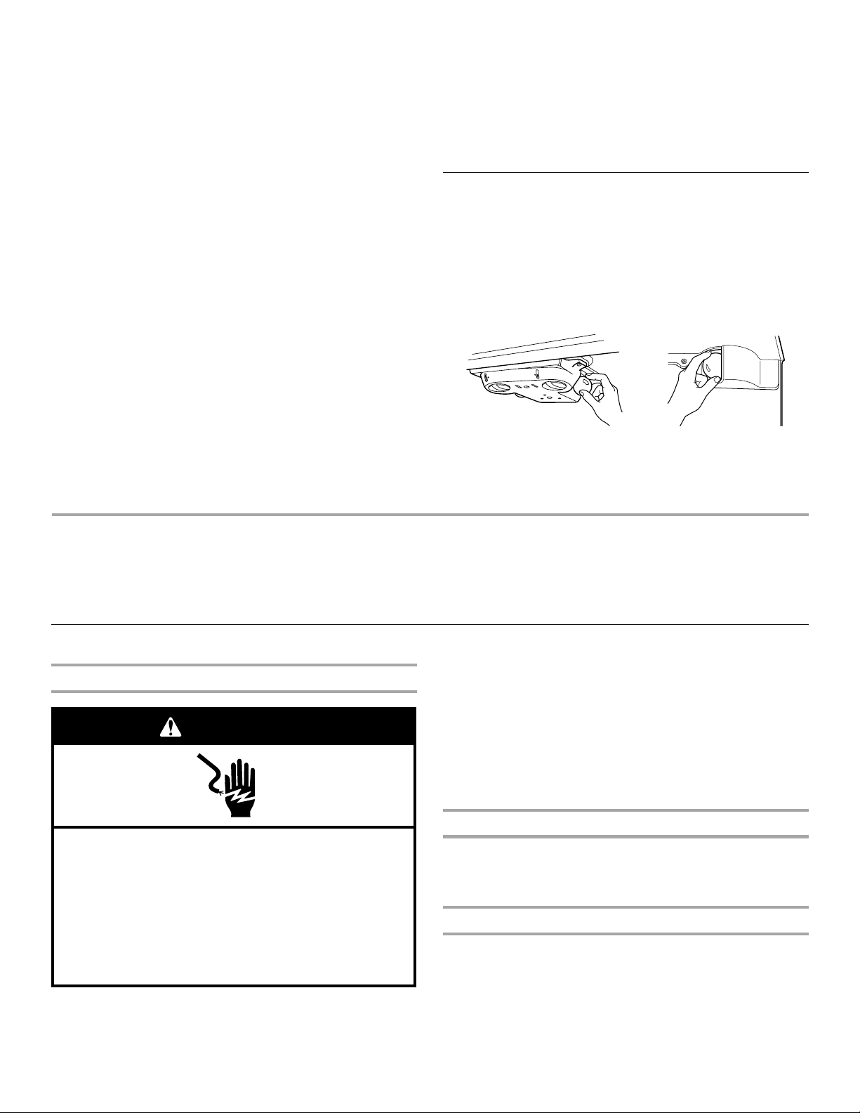
Changing the Light Bulbs
NOTE: Not all bulbs will fit your refrigerator. Be sure to replace the
bulb with an appliance bulb of the same size, shape, and wattage.
1. Unplug refrigerator or disconnect power.
2. Remove the bulb from behind the control panel in the
refrigerator or from behind the light shield in the freezer (on
some models). Replace it with an appliance bulb of the same
wattage.
3. Plug in refrigerator or reconnect power.
1
ARMER
W
2
R
WARME
1
FREEZER
3
2
E
R
3
3
E
R
4
O
C
5
3
G
N
I
T
T
E
S
D
E
D
N
E
M
M
O
C
R
E
R
O
T
A
R
E
G
I
R
F
O
C
L
O
4
G
N
I
T
T
E
S
D
E
ND
E
M
M
5
R
E
L
O
O
C
S
T
N
E
M
T
S
U
J
D
A
N
E
E
W
T
E
B
S
R
U
O
H
4
2
W
O
L
L
A
R
E
TROUBLESHOOTING
First try the solutions suggested here or visit our website and reference FAQs (Frequently Asked Questions)
to possibly avoid the cost of a service call.
In the U.S.A., www.kitchenaid.com In Canada, www.kitchenaid.ca
Refrigerator Operation
The refrigerator will not operate
WARNING
Electrical Shock Hazard
Plug into a grounded 3 prong outlet.
Do not remove ground prong.
Do not use an adapter.
Do not use an extension cord.
Failure to follow these instructions can result in death,
fire, or electrical shock.
■ Power cord unplugged? Plug into a grounded 3 prong outlet.
■ Outlet working? Plug in a lamp to see if the outlet is working.
■ Household fuse blown or circuit breaker tripped? Replace
the fuse or reset the circuit breaker. If the problem continues,
call an electrician.
■ Controls on? Make sure the refrigerator controls are on. See
“Using the Control(s).”
■ New installation? Allow 24 hours following installation for the
refrigerator to cool completely.
NOTE: Adjusting the temperature controls to coldest setting
will not cool either compartment more quickly.
The motor seems to run too much
Your new refrigerator may run longer than your old one due to its
high-efficiency compressor and fans. The unit may run even
longer if the room is warm, a large food load is added, doors are
opened often, or if the doors have been left open.
The refrigerator seems noisy
Refrigerator noise has been reduced over the years. Due to this
reduction, you may hear intermittent noises from your new
refrigerator that you did not notice from your old model. Below are
listed some normal sounds with explanations.
■ Buzzing - heard when the water valve opens to fill the ice
maker
12
■ Pulsating - fans/compressor adjusting to optimize
performance
■ Hissing/Rattling - flow of refrigerant, movement of water
lines, or from items placed on top of the refrigerator
■ Sizzling/Gurgling - water dripping on the heater during
defrost cycle
■ Popping - contraction/expansion of inside walls, especially
during initial cool-down
■ Water running - may be heard when ice melts during the
defrost cycle and water runs into the drain pan
■ Creaking/Cracking - occurs as ice is being ejected from the
ice maker mold.
The doors will not close completely
■ Door blocked open? Move food packages away from door.
■ Bin or shelf in the way? Push bin or shelf back in the correct
position.
The doors are difficult to open
WARNING
Explosion Hazard
Use nonflammable cleaner.
Failure to do so can result in death, explosion, or fire.
■ Gaskets dirty or sticky? Clean gaskets and contact surfaces
with mild soap and warm water. Rinse and dry with soft cloth.
Temperature and Moisture
Temperature is too warm
■ New installation? Allow 24 hours following installation for the
refrigerator to cool completely.
■ Door(s) opened often or left open? Allows warm air to enter
refrigerator. Minimize door openings and keep doors fully
closed.
■ Large load of food added? Allow several hours for
refrigerator to return to normal temperature.
■ Controls set correctly for the surrounding conditions?
Adjust the controls a setting colder. Check temperature in
24 hours. See “Using the Control(s).”
There is interior moisture buildup
NOTE: Some moisture buildup is normal.
■ Humid room? Contributes to moisture buildup.
■ Door(s) opened often or left open? Allows humid air to enter
refrigerator. Minimize door openings and keep doors fully
closed.
Ice and Water
The ice maker is not producing ice or not enough ice
■ Refrigerator connected to a water supply and the supply
shutoff valve turned on? Connect refrigerator to water
supply and turn water shutoff valve fully open.
■ Kink in the water source line? A kink in the line can reduce
water flow. Straighten the water source line.
■ Ice maker turned on? Make sure wire shutoff arm or switch
(depending on model) is in the ON position.
■ New installation? Wait 24 hours after ice maker installation
for ice production to begin. Wait 72 hours for full ice
production.
■ Freezer door closed completely? Firmly close the freezer
compartment door. If the freezer compartment door will not
close all the way, see “The doors will not close completely,”
earlier in this section.
■ Large amount of ice recently removed? Allow 24 hours for
ice maker to produce more ice.
■ Ice cube jammed in the ice maker ejector arm?
Remove ice from the ejector arm with a plastic utensil.
■ Water filter installed on the refrigerator? Remove filter and
operate ice maker. If ice volume improves, then the filter may
be clogged or incorrectly installed. Replace filter or reinstall it
correctly.
■ Reverse osmosis water filtration system connected to
your cold water supply? This can decrease water pressure.
See “Water Supply Requirements.”
The ice cubes are hollow or small
NOTE: This is an indication of low water pressure.
■ Water shutoff valve not fully open? Turn the water shutoff
valve fully open.
■ Kink in the water source line? A kink in the line can reduce
water flow. Straighten the water source line.
■ Water filter installed on the refrigerator? Remove filter and
operate ice maker. If ice quality improves, then the filter may
be clogged or incorrectly installed. Replace filter or reinstall it
correctly.
■ Reverse osmosis water filtration system connected to
your cold water supply? This can decrease water pressure.
See “Water Supply Requirements.”
■ Questions remain regarding water pressure? Call a
licensed, qualified plumber.
Off-taste, odor or gray color in the ice
■ New plumbing connections? New plumbing connections
can cause discolored or off-flavored ice.
■ Ice stored too long? Discard ice. Wash ice bin. Allow
24 hours for ice maker to make new ice.
■ Odor transfer from food? Use airtight, moisture proof
packaging to store food.
■ Are there minerals (such as sulfur) in the water? A water
filter may need to be installed to remove the minerals.
■ Water filter installed on the refrigerator? Gray or dark
discoloration in ice indicates that the water filtration system
needs additional flushing. Flush the water system before using
a new water filter. Replace water filter when indicated. See
“Water Filtration System.”
13

The water dispenser will not operate properly
■ Refrigerator connected to a water supply and the supply
shutoff valve turned on? Connect refrigerator to water
supply and turn water shutoff valve fully open.
■ Kink in the water source line? Straighten the water source
line.
■ New installation? Flush and fill the water system. See “Water
Dispenser.”
■ Is the water pressure at least 35 psi (241 kPa)? The water
pressure to the home determines the flow from the dispenser.
See “Water Supply Requirements.”
■ Water filter installed on the refrigerator? Remove filter and
operate dispenser. If water flow increases, the filter may be
clogged or incorrectly installed. Replace filter or reinstall it
correctly.
■ Refrigerator door closed completely? Close the door firmly.
If it does not close completely, see “The doors will not close
completely,” earlier in this section.
■ Recently removed the doors? Make sure the water
dispenser wire/tube assembly has been properly reconnected.
See “Refrigerator Doors.”
■ Reverse osmosis water filtration system connected to
your cold water supply? This can decrease water pressure.
See “Water Supply Requirements.”
Water is leaking from the dispenser system
WATER FILTER
CERTIFICATIONS
NOTE: One or two drops of water after dispensing is normal.
■ Glass not being held under the dispenser long enough?
Hold the glass under the dispenser 2 to 3 seconds after
releasing the dispenser lever.
■ New installation? Flush the water system. See “Water
Dispenser.”
■ Recently changed water filter? Flush the water system. See
“Water Dispenser.”
■ Water on the floor near the base grille? Make sure the water
dispenser tube connections are fully tightened. See
“Refrigerator Doors.”
Water from the dispenser is warm
NOTE: Water from the dispenser is only chilled to 50°F (10°C).
■ New installation? Allow 24 hours after installation for the
water supply to cool completely.
■ Recently dispensed large amount of water? Allow 24 hours
for water supply to cool completely.
■ Water not been recently dispensed? The first glass of water
may not be cool. Discard the first glass of water.
■ Refrigerator connected to a cold water pipe? Make sure
the refrigerator is connected to a cold water pipe. See “Water
Supply Requirements.”
Accessories
To order stainless steel cleaner or replacement filters, call
1-800-442-9991 and ask for the part number listed below or
contact your authorized KitchenAid dealer. In Canada, call
1-800-461-5681.
Stainless Steel Cleaner and Polish:
Order Part #4396920
Replacement Filter:
Order Part #4396701 (L200V / NL120V / NLC120V)
14
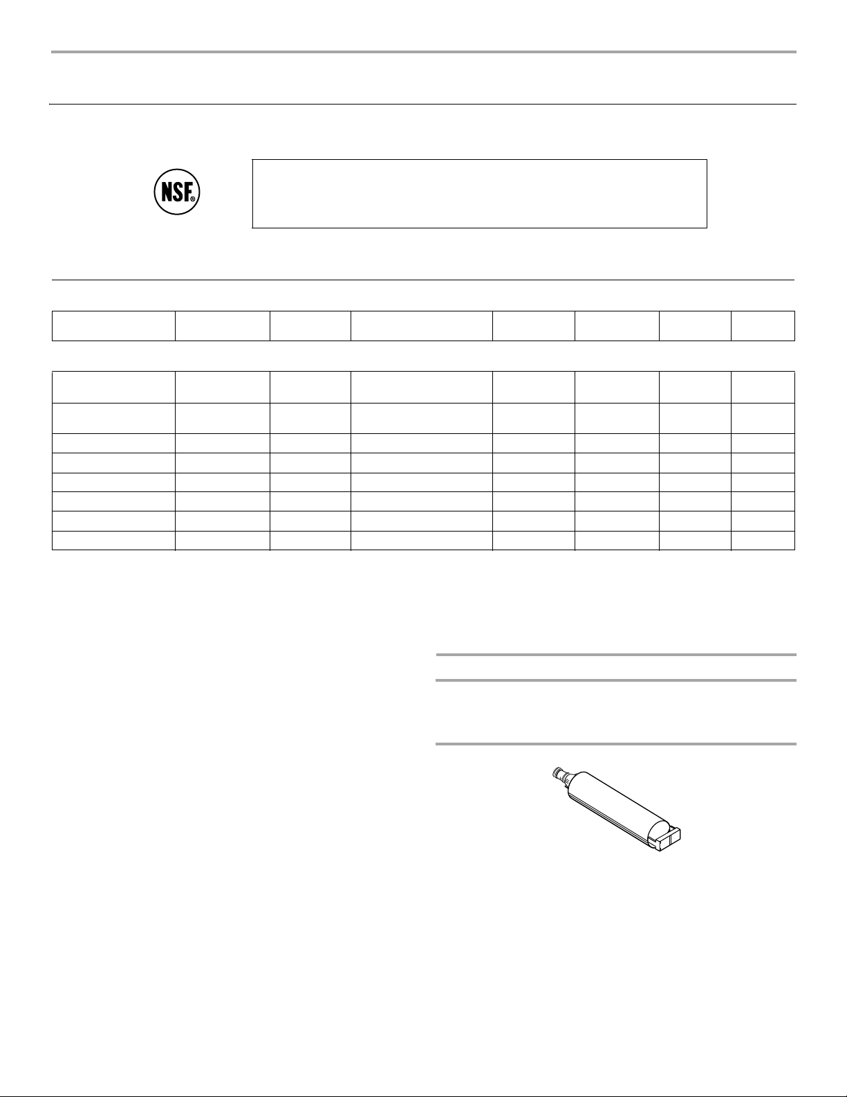
PRODUCT DATA SHEETS
®
Base Grille Water Filtration System
Model WF-L200V Capacity 200 Gallons (757 Liters)
Model WF-NL120V Capacity 120 Gallons (454 Liters)
System tested and certified by NSF International against NSF/ANSI Standard 53 for
the reduction of Lead, Mercury, Benzene, p-dichlorobenzene, O-Dichlorobenzene,
Toxaphene, Ethyl Benzene, 1,2,4-trichlorobenzene and against NSF/ANSI Standard
42 for the reduction of Chlorine Taste and Odor and Particulate Class III.
This system has been tested according to ANSI/NSF 42/53 for the reduction of the substances listed below. The concentration of
the indicated substances in water entering the system was reduced to a concentration less than or equal to the permissible limit for
water leaving the system, as specified in ANSI/NSF 42/53.
Substance Reduction
Aesthetic Effects
Chlorine Taste/Odor
Particulate Class lll
Contaminant
Reduction
Lead:@ pH 6.5
Lead: @ pH 8.5
Mercury: @ pH 6.5
Mercury: @ pH 8.5
Benzene 0.005 mg/L 0.0157 mg/L 0.015 mg/L ± 10% 0.002 mg/L 0.00083 mg/L 87.26% 94.71%
p-dichlorobenzene 0.075 mg/L 0.210 mg/L 0.225 mg/L ± 10% 0.0005 mg/L 0.0005 mg/L 99.76% 99.76%
O-Dichlorobenzene 0.60 1.84 1.8 ± 10% 0.20 0.0418 89.13 97.73
Toxaphene 0.003 0.0143 0.015 ± 10% 0.0012 0.0010 91.60 93.00
Ethyl Benzene 0.70 2.00 2.1 ± 10% 0.40 0.085 80.00 95.75
1,2,4- trichlorobenzene 0.07 0.232 0.21 ± 10% 0.0041 0.0016 98.23 99.31
NSF Reduction
Requirements
≥50%
*
≥85%
NSF Reduction
Requirements
0.01mg/L
0.01mg /L
0.002 mg/L
0.002 mg/L
Average
Influent
1.9 mg/L
49333/mL
Average
Influent
0.14 mg/L
†
0.15 mg/L
0.0059 mg/L
0.0054 mg/L
Influent Challenge
Concentration
2.0 mg/L ± 10%
At least 10,000 particles/mL
Influent Challenge
Concentration
0.15 mg/L ± 10%
†
0.15 mg /L ± 10%
0.006 mg/L ± 10%
0.006 mg /L ± 10%
Maximum
Effluent
0.07 mg/L
640/mL**
Maximum
Effluent
0.0014 mg/L
0.0069 mg/L
0.0009 mg/L
0.0007mg /L
Average
Effluent
0.06 mg/L
312/mL
Average
Effluent
0.0011 mg/L
0.0042 mg/L
0.0004 mg/L
0.00043 mg/L
Minimum%
Reduction
>75%
98.7%
Minimum%
Reduction
99.00%
95.40%%
84.74%
87.03%
Average%
Reduction
>75%
99.0%
Average%
Reduction
99.21%
97.20%
93.22%
92.03%
Test Parameters: pH = 7.5 ± 0.5 unless otherwise noted. Flow = 0.5 gpm (1.9 Lpm). Pressure = 60 psig (413.7 kPa). Temp. = 63°F
(17.2°C).
■ It is essential that operational, maintenance, and filter
replacement requirements be carried out for the product to
perform as advertised.
■ Model WF-L200V: The filter monitor system measures the
■ Refer to the front cover or “Accessories” section for the
Manufacturer’s name, address and telephone number.
■ Refer to the “Warranty” section for the Manufacturer’s limited
warranty.
amount of water that passes through the filter and alerts you
to replace the filter. When 90% of the filter’s rated life is used,
the filter indicator light changes from green to yellow. When
100% of the filter’s rated life is used, the filter indicator light
changes from yellow to red, and it is recommended that you
replace the filter. Use replacement filter L200V / NL120V, part
#4396701. 2007 suggested retail price of $34.99 U.S.A./
$45.99 Canada. Prices are subject to change without notice.
Application Guidelines/Water Supply Parameters
Water Supply
Water Pressure
Water Temperature
Service Flow Rate
City or Well
30 - 120 psi (207 - 827 kPa)
33° - 100°F (0.6° - 37.8°C)
0.5 GPM (1.9 L/min.) @ 60 psi
Model WF-NL120V: Change the water filter every
6 months. Use replacement filter L200V / NL120V, part
#4396701. 2007 suggested retail price of $34.99 U.S.A./
$45.99 Canada. Prices are subject to change without notice.
■ The product is for cold water use only.
■ Do not use with water that is microbiologically unsafe or of
unknown quality without adequate disinfection before or after
the system.
Class Ill particle size: > 5 to < 15 um
*
Test requirement is at least 100,000 particles/mL of AC Fine Test Dust.
**
†
These contaminants are not necessarily in your water supply. Performance may vary based on local water conditions.
NSF is a registered trademark of NSF International.
15
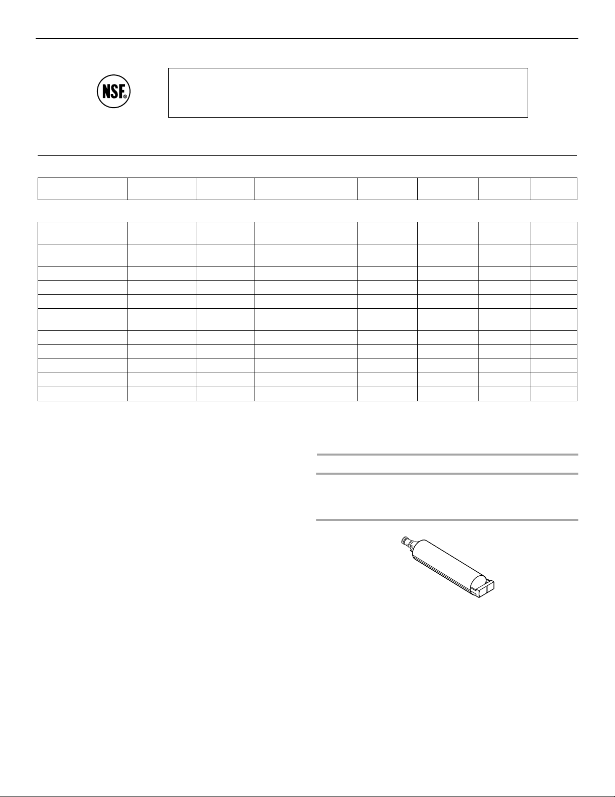
Base Grille Water Filtration System
Model WF-NLC120V Capacity 120 Gallons (454 Liters)
System tested and certified by NSF International against NSF/ANSI Standard 53 for the
reduction of Lead, Mercury, Benzene, p-dichlorobenzene, Cysts, Turbidity, Asbestos,
Endrin, O-Dichlorobenzene, Toxaphene, Ethyl Benzene, 1,2,4-trichlorobenzene and against
NSF/ANSI Standard 42 for the reduction of Chlorine Taste and Odor and Particulate Class I.
This system has been tested according to ANSI/NSF 42/53 for the reduction of the substances listed below. The concentration of
the indicated substances in water entering the system was reduced to a concentration less than or equal to the permissible limit for
water leaving the system, as specified in ANSI/NSF 42/53.
Substance Reduction
Aesthetic Effects
Chlorine Taste/Odor
Particulate Class l
Contaminant
Reduction
Lead: @ pH 6.5
Lead: @ pH 8.5
Mercury: @ pH 6.5
Mercury: @ pH 8.5
Benzene 0.005 mg/L 0.0153 mg/L 0.015 mg/L ± 10% 0.0036 mg/L 0.0014 mg/L 76.47% 90.84%
p-dichlorobenzene 0.075 mg/L 0.215 mg/L 0.225 mg/L ± 10% 0.0037 mg/L 0.0010 mg/L 98.27% 99.52%
Asbestos 99.0%** 842 x 10
‡
Cysts
Turb idi ty
Endrin 0.002 0.0056 0.006 ± 10% 0.0007 0.0004 87.50 92.85
O-Dichlorobenzene 0.60 1.84 1.8 ± 10% 0.33 0.071 82.06 96.14
Toxaphene 0.003 0.0143 0.015 ± 10% 0.001 0.001 93.00 93.00
Ethyl Benzene 0.70 2.00 2.1 ± 10% 0.60 0.169 70.00 91.55
1,2,4- trichlorobenzene 0.07 0.232 0.21 ± 10% 0.0025 0.0007 98.92 99.69
NSF Reduction
Requirements
≥50%
*
≥85%
NSF Reduction
Requirements
0.01mg/L
0.01mg /L
0.002 mg/L
0.002 mg/L
99.95%
0.5 NTU
Average
Influent
1.9 mg/L
5,300,000/mL
Average
Influent
0.14 mg/L
0.15 mg /L
0.0058 mg/L
0.0055 mg/L
165,500/mL
11.75 NTU
†
†
7
Influent Challenge
Concentration
2.0 mg/L ± 10%
At least 10,000 particles/mL
Influent Challenge
Concentration
0.15 mg/L ± 10%
0.15 mg /L ± 10%
0.006 mg/L ± 10%
0.006 mg /L ± 10%
107 to 108 fibers/L
50,000/L min.
11 ± 1 NTU
††
Maximum
Effluent
0.12 mg/L
50,000/mL**
Maximum
Effluent
0.001 mg/L
0.001 mg/L
0.0005 mg/L
0.0013 mg /L
1.6 x 10⁷ mg/L 1.6 x 10⁷ mg/L 99.81 99.81%
1 mg/L
0.38 NTU
Average
Effluent
0.08 mg/L
15,725/mL
Average
Effluent
0.001 mg/L
0.001 mg/L
0.0003 mg/L
0.0005 mg/L
1 mg/L
0.22 NTU
Minimum%
Reduction
>75%
99.0%
Minimum%
Reduction
99.29%
99.32%
91.37%
76.36%
99.99%
96.76%
Average%
Reduction
>75%
99.7%
Average%
Reduction
99.29%
99.32%
94.82%
90.90%
99.99%
98.12%
Test Parameters: pH = 7.5 ± 0.5 unless otherwise noted. Flow = 0.5 gpm (1.9 Lpm). Pressure = 60 psig (413.7 kPa). Temp. = 63°F
(17.2°C).
■ It is essential that operational, maintenance, and filter
replacement requirements be carried out for the product to
■ Refer to the “Warranty” section for the Manufacturer’s limited
warranty.
perform as advertised.
■ Model WF-NLC120V: Change the water filter every 6 months.
Use replacement cartridge NLC120V, part #4396701. 2007
suggested retail price of $34.99 U.S.A./$45.99 Canada. Prices
are subject to change without notice.
■ The product is for cold water use only.
■ Do not use with water that is microbiologically unsafe or of
Application Guidelines/Water Supply Parameters
Water Supply
Water Pressure
Water Temperature
Service Flow Rate
City or Well
30 - 120 psi (207 - 827 kPa)
33° - 100°F (0.6° - 37.8°C)
0.5 GPM (1.89 L/min.) @ 60 psi
unknown quality without adequate disinfection before or after
the system. Systems certified for cyst reduction may be used
on disinfected waters that may contain filterable cysts.
■ Refer to the front cover or “Accessories” section for the
Manufacturer’s name, address and telephone number.
Class I particle size: >0.5 to <1 um
*
Test requirement is at least 100,000 particles/mL of AC Fine Test Dust.
**
†
These contaminants are not necessarily in your water supply. Performance may vary based on local water conditions.
††
Fibers greater than 10 um in length
‡
Based on the use of Cryptosporidium parvum oocysts
® NSF is a registered trademark of NSF International.
16
KITCHENAID® REFRIGERATOR WARRANTY
For one year from the date of purchase, when this major appliance is operated and maintained according to instructions attached to or furnished with
the product, KitchenAid brand of Whirlpool Corporation or Whirlpool Canada LP (hereafter “KitchenAid”) will pay for factory specified parts and repair
labor to correct defects in materials or workmanship that existed when this major appliance was purchased. Service must be provided by a
KitchenAid designated service company. YOUR SOLE AND EXCLUSIVE REMEDY UNDER THIS LIMITED WARRANTY SHALL BE PRODUCT REPAIR
AS PROVIDED HEREIN. This limited warranty is valid only in the United States or Canada and applies only when the major appliance is used in the
country in which it was purchased. Proof of original purchase date is required to obtain service under this limited warranty.
On models with a water filter: 30 day limited warranty on water filter. For 30 days from the date of purchase, when this filter is operated and
maintained according to instructions attached to or furnished with the product, KitchenAid will pay for a replacement water filter to correct defects in
materials and workmanship.
SECOND THROUGH FIFTH YEAR LIMITED WARRANTY ON CAVITY LINER AND SEALED REFRIGERATION SYSTEM
LIMITED WARRANTY
In the second through fifth year from the date of purchase, when this major appliance is operated and maintained according to instructions attached
to or furnished with the product, KitchenAid will pay for replacement or repair of the refrigerator/freezer cavity liner (including labor costs) if the part
cracks due to defective materials or workmanship that existed when this major appliance was purchased. Also, in the second through fifth year from
the date of purchase, when this major appliance is operated and maintained according to instructions attached to or furnished with the product,
KitchenAid will pay for factory specified parts and repair labor for the following components to correct defects in materials or workmanship in the
sealed refrigeration system that existed when this major appliance was purchased: compressor, evaporator, condenser, dryer, and connecting tubing.
SIXTH THROUGH TENTH YEAR LIMITED WARRANTY ON SEALED REFRIGERATION SYSTEM
In the sixth through tenth year from the date of purchase, when this major appliance is operated and maintained according to instructions attached to
or furnished with the product, KitchenAid will pay for factory specified parts for the following components to correct defects in materials or
workmanship in the sealed refrigeration system that existed when this major appliance was purchased: compressor, evaporator, condenser, dryer,
and connecting tubing.
LIFETIME LIMITED WARRANTY ON DOOR BINS AND CAN RACKS
For the lifetime of the product from the date of purchase, when this major appliance is operated and maintained according to instructions attached to
or furnished with the product, KitchenAid will pay for replacement of all SLIDE N LOCK™ Door Bins and SLIDE N LOCK™ Can Racks due to
defective materials or workmanship that existed when this major appliance was purchased.
ITEMS EXCLUDED FROM WARRANTY
This limited warranty does not cover:
1. Replacement parts or repair labor if this major appliance is used for other than normal, single-family household use or when it is used in a
manner that is inconsistent to published user or operator instructions and/or installation instructions.
2. Service calls to correct the installation of your major appliance, to instruct you on how to use your major appliance, to replace or repair house
fuses, or to correct house wiring or plumbing.
3. Service calls to repair or replace appliance light bulbs, air filters or water filters. Consumable parts are excluded from warranty coverage.
4. Damage resulting from accident, alteration, misuse, abuse, fire, flood, acts of God, improper installation, installation not in accordance with
electrical or plumbing codes, or use of products not approved by KitchenAid.
5. Cosmetic damage, including scratches, dents, chips or other damage to the finish of your major appliance, unless such damage results from
defects in materials or workmanship and is reported to KitchenAid within 30 days from the date of purchase.
6. Any food or medicine loss due to refrigerator or freezer product failures.
7. Pickup and delivery. This major appliance is intended to be repaired in your home.
8. Repairs to parts or systems resulting from unauthorized modifications made to the appliance.
9. Expenses for travel and transportation for product service if your major appliance is located in a remote area where service by an authorized
KitchenAid servicer is not available.
10. The removal and reinstallation of your major appliance if it is installed in an inaccessible location or is not installed in accordance with
KitchenAid's published installation instructions.
11. Replacement parts or repair labor on major appliances with original model/serial numbers that have been removed, altered or cannot be easily
determined.
DISCLAIMER OF IMPLIED WARRANTIES
IMPLIED WARRANTIES, INCLUDING ANY IMPLIED WARRANTY OF MERCHANTABILITY OR IMPLIED WARRANTY OF FITNESS FOR A
PARTICULAR PURPOSE, ARE LIMITED TO ONE YEAR OR THE SHORTEST PERIOD ALLOWED BY LAW. Some states and provinces do not allow
limitations on the duration of implied warranties of merchantability or fitness, so this limitation may not apply to you. This warranty gives you specific
legal rights, and you also may have other rights that vary from state to state or province to province.
LIMITATION OF REMEDIES; EXCLUSION OF INCIDENTAL AND CONSEQUENTIAL DAMAGES
YOUR SOLE AND EXCLUSIVE REMEDY UNDER THIS LIMITED WARRANTY SHALL BE PRODUCT REPAIR AS PROVIDED HEREIN. KITCHENAID
SHALL NOT BE LIABLE FOR INCIDENTAL OR CONSEQUENTIAL DAMAGES. Some states and provinces do not allow the exclusion or limitation of
incidental or consequential damages, so these limitations and exclusions may not apply to you. This warranty gives you specific legal rights, and you
also may have other rights that vary from state to state or province to province.
If outside the 50 United States and Canada, contact your authorized KitchenAid dealer to determine if another warranty applies. 6/08
For additional product information, in the U.S.A., visit www.kitchenaid.com In Canada, visit www.kitchenaid.ca
If you do not have access to the Internet and you need assistance using your product or you would like to schedule service, you may contact
KitchenAid at the number below.
Have your complete model number ready. You can find your model number and serial number on the label, located on the inside wall of the
refrigerator compartment.
For assistance or service in the U.S.A., call 1-800-422-1230. In Canada, call 1-800-807-6777.
If you need further assistance, you can write to KitchenAid with any questions or concerns at the address below:
In the U.S.A.:
KitchenAid Brand Home Appliances
Customer eXperience Center
553 Benson Road
Benton Harbor, MI 49022-2692
Please include a daytime phone number in your correspondence.
Please keep this User Instructions and model number information for future reference.
In Canada:
KitchenAid Brand Home Appliances
Customer eXperience Centre
1901 Minnesota Court
Mississauga, Ontario L5N 3A7
17
 Loading...