

KitchenAid KTRC22KMBT05, KTRC22EMBL05, KTRP22KRWH02, KTRP22KRBT02, KTRP19KRWH01 Owner’s Manual
...
REFRIGERATOR USE & CARE GUIDE
MANUAL DE USO Y CUIDADO DEL
GUIDE D'UTILISATION ET D'ENTRETIEN DU
Table of Contents / Indice / Table des mati_res
ASSISTANCE OR SERVICE ............................ 1
REFRIGERATOR SAFETY ............................... 2
INSTALLATION INSTRUCTIONS ................... 3
REFRIGERATOR USE ................................... 11
REFRIGERATOR CARE ................................. 13
TROUBLESHOOTING .................................... 14
WATER FILTER CERTIFICATIONS .............. 16
PRODUCT DATA SHEETS ............................ 17
WARRANTY .................................................... 19
Kitchen kid
REFRIGERADOR
p p
REFRIGERATEUR
AYUDA O SERVIClO TECNICO .................... 20
SEGURIDAD DEL REFRIGERADOR ............ 20
INSTRUCCIONES DE INSTALACION .......... 21
USO DE SU REFRIGERADOR ...................... 30
CUIDADO DE SU REFRIGERADOR ............. 32
SOLUClON DE PROBLEMAS ....................... 33
HOJA DE DATOS DEL PRODUCTO ............ 35
GARANTIA ...................................................... 37
ASSISTANCE OU SERVICE .......................... 38
SleCURITle DU RleFRIGleRATEUR ................ 38
INSTRUCTIONS D'INSTALLATION .............. 39
UTILISATION DU RF=FRIGF=RATEUR ........... 48
ENTRETIEN DU RleFRIGleRATEUR ............. 50
DlePANNAGE .................................................. 51
FEUILLES DE DONNleES
SUR LE PRODUIT .......................................... 53
GARANTIE ...................................................... 55
Assistance or Service
If you need assistance or service, first see the "Troubleshooting"
section. Additional help is available. Call us at 1-800-422-1230
from anywhere in the U,S.A., or write:
KitchenAid Brand Home Appliances
Customer eXperience Center
553 Benson Road
Benton Harbor, MI 49022-2692
In Canada, for installation and service call, 1-800-807-6777.
For assistance call 1-800-461-5681 Monday to Friday 8:00 a.m. -
6:00 p.m. (EST), Saturday 8:30 - 4:30 p.m. (EST), or write:
KitchenAid Canada
Customer Interaction Centre
1901 Minnesota Court
Mississauga, Ontario L5N 3A7
Information may also be obtained by visiting our website at
www.kitchenaid.com
In Canada, visit www.KitchenAid.ca.
Please include a daytime phone number in your correspondence.
Keep this book and your sales slip together for future
reference. You must provide proof of purchase or installation
date for in-warranty service.
Write down the following information about your appliance to help
you obtain assistance or service if you ever need it. You will need
to know your complete model number and serial number. You can
find this information on the model and serial number label, located
on the inside wall of the refrigerator compartment.
Dealer name
Serial number
Address
Phone number
Model number
Purchase date
Toorder stainless steel cleaner or replacement filters, call
1-800-442-9991 and ask for the part number listed below or
contact your authorized KitchenAid dealer. In Canada, call
1-800-461-5681.
Stainless Steel Cleaner & Polish:
Order Part #8171420
Replacement Filter:
Order Part #4396701 (L200V / NL120V / NLC120V)
2314464
REFRIGERATOR SAFETY
Your safety and the safety of others are very important.
We have provided many important safety messages in this manual and on your appliance. Always read and obey all safety
messages.
This is the safety alert symbol.
This symbol alerts you to potential hazards that can kill or hurt you and others.
All safety messages will follow the safety alert symbol and either the word "DANGER" or "WARNING."
These words mean:
You can be killed or seriously injured if you don't immediately
follow instructions.
You can be killed or seriously injured if you don't follow
instructions.
All safety messages will tell you what the potential hazard is, tell you how to reduce the chance of injury, and tell you what can
happen if the instructions are not followed.
IMPORTANT SAFETY INSTRUCTIONS
WARNING: To reduce the risk of fire, electric shock, or injury when using your refrigerator, follow these basic precautions:
• Plug into a grounded 3 prong outlet. • Use nonflammable cleaner.
• Do not remove ground prong.
• Do not use an adapter.
mDo not use an extension cord.
• Disconnect power before servicing.
mReplace all parts and panels before operating.
mRemove doors from your old refrigerator.
SAVE THESE INSTRUCTIONS
• Keep flammable materials and vapors, such as gasoline,
away from refrigerator.
mUse two or more people to move and install refrigerator.
,,,Disconnect power before installing ice maker (on ice maker
kit ready models only).
mUse a sturdy glass when dispensing ice or water (on some
models).
Proper Disposal of Your Old Refrigerator
IMPORTANT: Child entrapment and suffocation are not problems
of the past. Junked or abandoned refrigerators are still dangerous
- even if they will sit for "just a few days." If you are getting rid of
your old refrigerator, please follow these instructions to help
prevent accidents.
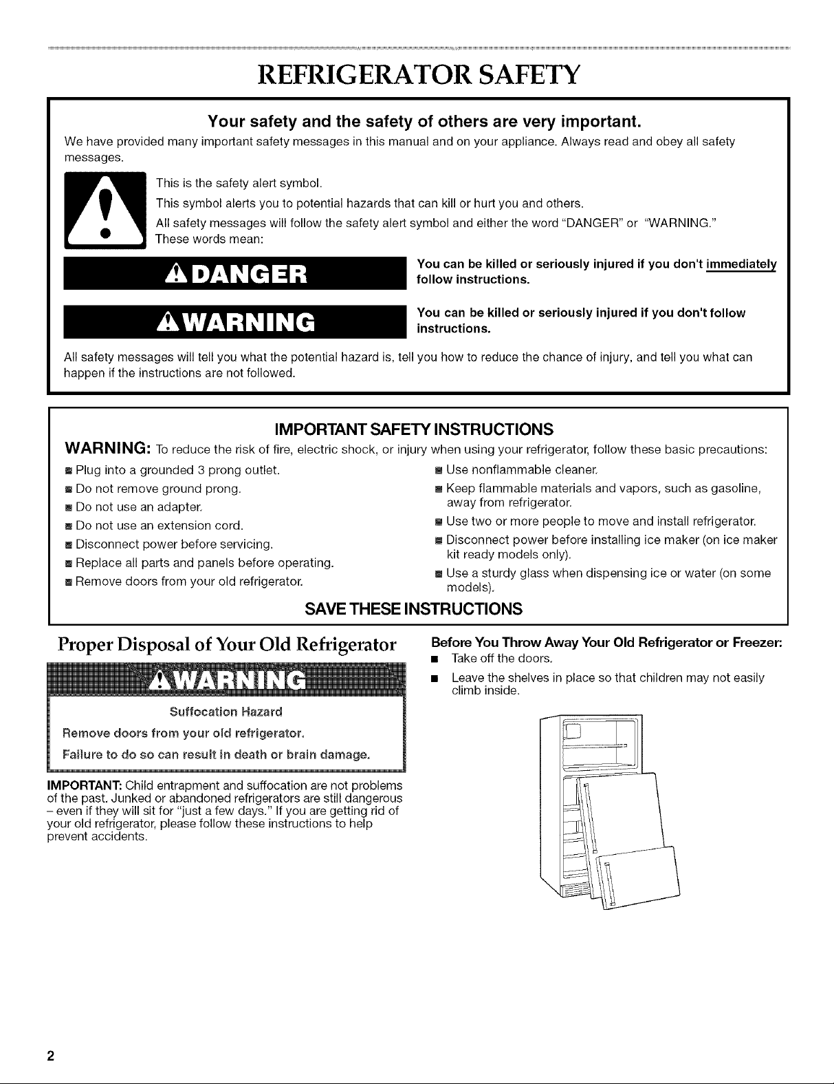
Before You Throw Away Your Old Refrigerator or Freezer:.
• Take off the doors.
• Leave the shelves in place so that children may not easily
climb inside.
INSTALLATION INSTRUCTIONS
i_iii_i_iii:x__;!!_:_:_iiii<t!i:!ii_ili!!_i_iiii:_i!,jii!t_;iil;i!_!!iS!!t_;_i:o i_i:¸
Excessive Weight Hazard
Use two or more people to move and install
refrigerator.
Failure to do so can result in back or other injury.
Remove the Packaging
Do not use sharp instruments, rubbing alcohol, flammable fluids,
or abrasive cleaners to remove tape or glue. These products can
damage the surface of your refrigerator. For more information, see
"Refrigerator Safety."
IMPORTANT: Do not remove the white foam air return insert from
behind the control panel on the ceiling of the refrigerator. If the
insert is removed, ice may migrate down from the freezer and
cause icicles to form.
When Moving Your Refrigerator:
Your refrigerator is heavy. When moving the refrigerator
for cleaning or service, be sure to protect the floor.
Always pulI the refrigerator straight out when moving it.
Do not wiggle or "walk" the refrigerator when trying to move
it, as floor damage could occur.
Explosion Hazard
Keep flammable materials and vapors, such as
gasoline, away from refrigerator.
Failure to do so can result in death, explosion, or fire.
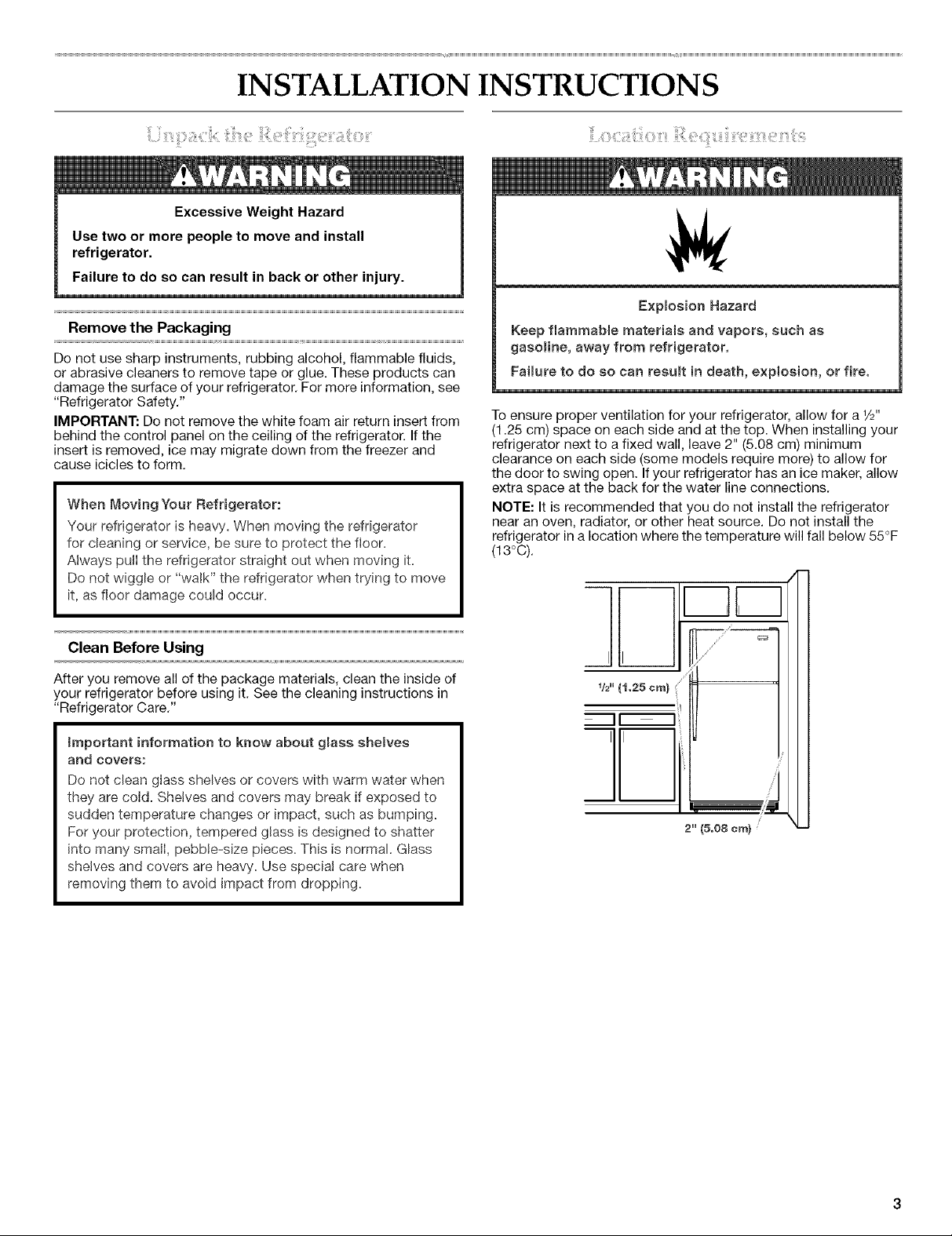
Toensure proper ventilation for your refrigerator, allow for a V2"
(1.25 cm) space on each side and at the top. When installing your
refrigerator next to a fixed wall, leave 2" (5.08 cm) minimum
clearance on each side (some models require more) to allow for
the door to swing open. If your refrigerator has an ice maker, allow
extra space at the back for the water line connections.
NOTE: It is recommended that you do not install the refrigerator
near an oven, radiator, or other heat source. Do not install the
refrigerator in a location where the temperature will fall below 55°F
(13°C).
Clean Before Using
After you remove all of the package materials, clean the inside of
your refrigerator before using it. See the cleaning instructions in
"Refrigerator Care."
_mportant information to know about glass shelves
and covers:
Do not clean glass shelves or covers with warm water when
they are cold. Shelves and covers may break if exposed to
sudden temperature changes or impact, such as bumping.
For your protection, tempered glass is designed to shatter
into many small, pebble-size pieces. This is normal. Glass
shelves and covers are heavy. Use special care when
removing them to avoid impact from dropping.
/
_!_"{1.25 em)
II I
II
i u
2" (5.08era)
Emectrica_ShockHazard
Pmugintoagrounded3 prong outleto
Do not remove ground prong.
Do not use an adapter.
Do not use an extension cord.
FaiJure to follow these }nstructions can resumt }n death,
fire, or electrical shock.
Before you move your refrigerator into its final location, it is
important to make sure you have the proper electrical connection.
Recommended Grounding Method
A 115 Volt, 60 Hz., AC only 15- or 20-amp fused, grounded
electrical supply is required. It is recommended that a separate
circuit serving only your refrigerator be provided. Use an outlet
that cannot be turned off by a switch. Do not use an
extension cord.
NOTE: Before performing any type of installation, cleaning, or
removing a light bulb, turn the control (Thermostat, Refrigerator or
Freezer Control depending on the model) to OFF and then
disconnect the refrigerator from the electrical source. When you
are finished, reconnect the refrigerator to the electrical source and
reset the control (Thermostat, Refrigerator or Freezer Control
depending on the model) to the desired setting.
Gather the required tools and parts before starting installation.
Read and follow the instructions provided with any tools listed
here.
IMPORTANT:
• If you turn the refrigerator on before the water line is
connected, turn the ice maker OFR
• All installations must meet local plumbing code requirements.
• Use copper tubing and check for leaks. Install copper tubing
only in areas where the household temperatures will remain
above freezing.
TOOLS NEEDED: Flat-blade screwdriver, 7A6"and 1/2"open-end
wrenches or two adjustable wrenches, 1/4"nut driver and drill bit,
hand drill or electric drill (properly grounded).
NOTE: Your refrigerator dealer has a kit available with a 1/4"
(6.35 mm) saddle-type shutoff valve, a union, and copper tubing.
Before purchasing, make sure a saddle-type valve complies with
your local plumbing codes. Do not use a piercing-type or 3/16"
(4.76 mm) saddle valve which reduces water flow and clogs more
easily.
Water Pressure
A cold water supply with water pressure of between 30 and
120 psi (207 - 827 kPa) is required to operate the water dispenser
and ice maker. Ifyou have questions about your water pressure,
call a licensed, qualified plumber.
Reverse Osmosis Water Supply
IMPORTANT: The pressure of the water supply coming out of a
reverse osmosis system going to the water inlet valve of the
refrigerator needs to be between 30 and 120 psi (207 - 827 kPa).
If a reverse osmosis water filtration system is connected to your
cold water supply, the water pressure to the reverse osmosis
system needs to be a minimum of 40 to 60 psi (276 - 414 kPa).
If the water pressure to the reverse osmosis system is less than
40 to 60 psi (276 - 414 kPa):
• Check to see whether the sediment filter in the reverse
osmosis system is blocked. Replace the filter if necessary.
• Allow the storage tank on the reverse osmosis system to refill
after heavy usage.
• If your refrigerator has a water filter cartridge, it may further
reduce the water pressure when used in conjunction with a
reverse osmosis system. Remove the water filter cartridge.
See "Water Filtration System."
If you have questions about your water pressure, call a licensed,
qualified plumber.
Read all directions before you begin.
IMPORTANT: If you turn the refrigerator on before the water line is
connected, turn the ice maker OFR
Connect to Water Line
1. Unplug refrigerator or disconnect power.
2. Turn OFF main water supply. Turn ON nearest faucet long
enough to clear line of water.
3. Locate a 1/2"to 11/4'' (1.25 cm to 3.18 cm) vertical cold water
pipe near the refrigerator.
IMPORTANT:
• Make sure it is a cold water pipe.
• Horizontal pipe will work, but drill on the top side of the
pipe, not the bottom. This will help keep water away from
the drill and normal sediment from collecting in the valve.
Determine the length of copper tubing you need. Measure
from the connection on the lower left rear of refrigerator to the
water pipe. Add 7 ft. (2.1 m) to allow for cleaning. Use 1/4"
(6.35 mm) O.D. (outside diameter) copper tubing. Be sure both
ends of copper tubing are cut square.
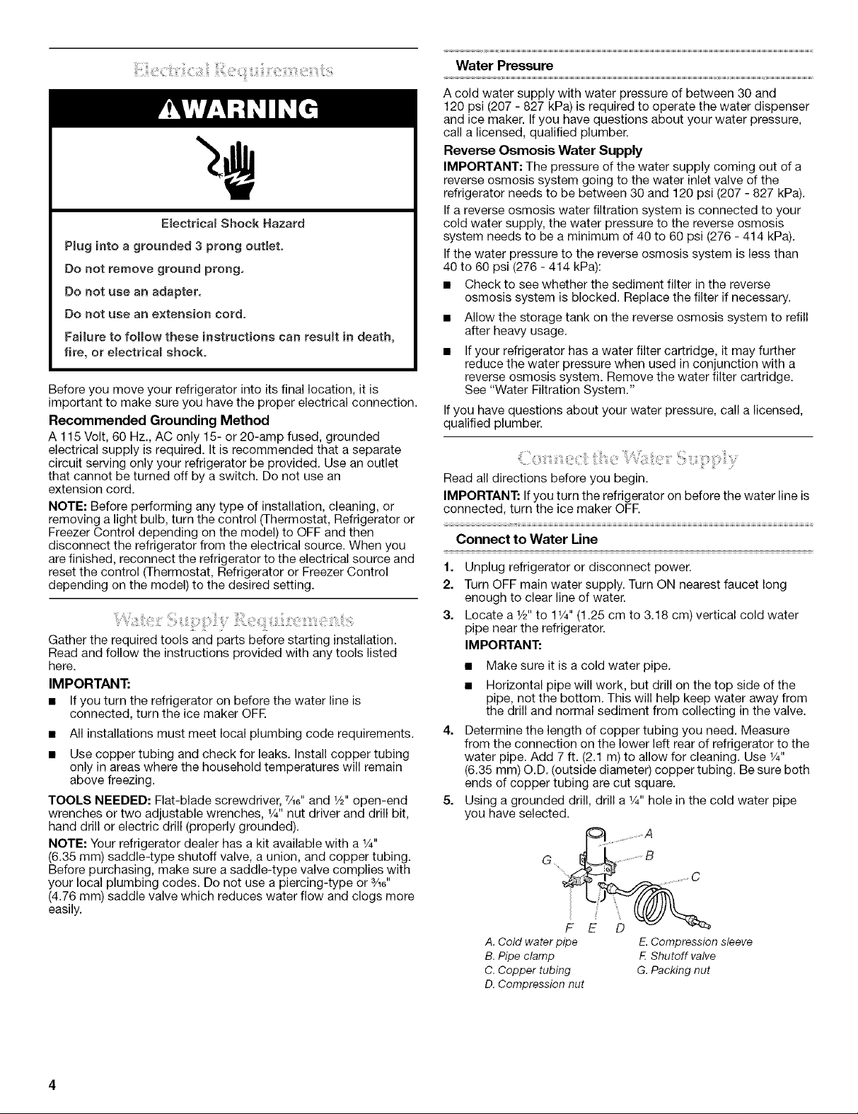
Using a grounded drill, drill a 1/4"hole in the cold water pipe
you have selected.
..................A
G ................B
.............. C
A. Cold waterpipe E.Compression sleeve
B.Pipe clamp F.Shutoff valve
C.Copper tubing G.Packing nut
D. Compression nut
6. Fasten the shutoff valve to the cold water pipe with the pipe
clamp. Be sure the outlet end is solidly in the 1/4"drilled hole in
the water pipe and that the washer is under the pipe clamp.
Tighten the packing nut. Tighten the pipe clamp screws slowly
and evenly so washer makes a watertight seal. Do not
overtighten or you may crush the copper tubing.
7. Slip the compression sleeve and compression nut onto the
copper tubing as shown. Insert the end of the tubing into the
outlet end squarely as far as it will go. Screw compression nut
onto outlet end with adjustable wrench. Do not overtighten.
8. Place the free end of the tubing in a container or sink, and turn
ON the main water supply. Flush the tubing until water is clear.
Turn OFF the shutoff valve on the water pipe. Coil the copper
tubing.
Connect to Refrigerator
Style 1
1. Unplug refrigerator or disconnect power.
2. Attach the copper tube to the valve inlet using a compression
nut and sleeve as shown. Tighten the compression nut. Do not
overtighten.
3. Use the tube clamp on the back of the refrigerator to secure
the tubing to the refrigerator as shown. This will help prevent
damage to the tubing when the refrigerator is pushed back
against the wall.
4. Turn shutoff valve ON.
5. Check for leaks. Tighten any connections (including
connections at the valve) or nuts that leak.
A
4. Turn shutoff valve ON.
5. Check for leaks. Tighten any nuts or connections (including
connections at the valve) that leak.
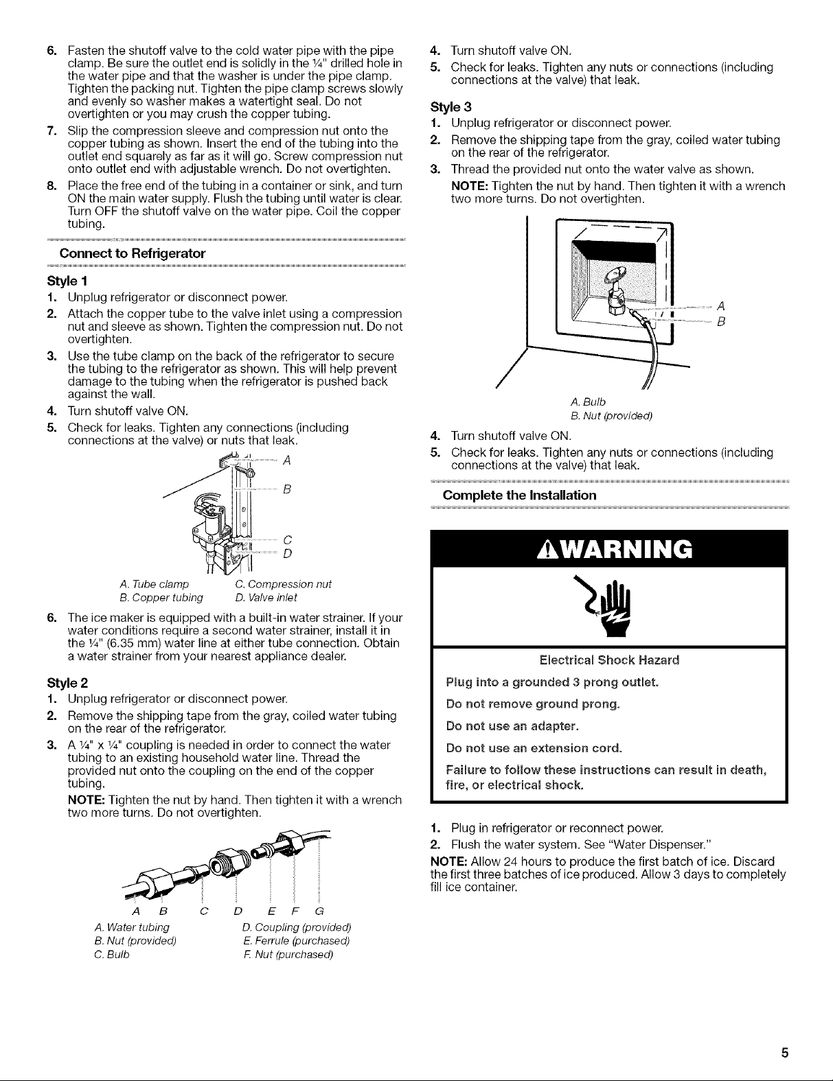
Style 3
1. Unplug refrigerator or disconnect power.
2. Remove the shipping tape from the gray, coiled water tubing
on the rear of the refrigerator.
3. Thread the provided nut onto the water valve as shown.
NOTE: Tighten the nut by hand. Then tighten it with a wrench
two more turns. Do not overtighten.
B
C
D
A. Tube clamp
B. Copper tubing
6=
The ice maker is equipped with a built-in water strainer. If your
C. Compression nut
D. Valve inlet
water conditions require a second water strainer, install it in
the 1/4"(6.35 mm) water line at either tube connection. Obtain
a water strainer from your nearest appliance dealer.
Style 2
1. Unplug refrigerator or disconnect power.
2. Remove the shipping tape from the gray, coiled water tubing
on the rear of the refrigerator.
3. A 1/4"x 1/4"coupling is needed in order to connect the water
tubing to an existing household water line. Thread the
provided nut onto the coupling on the end of the copper
tubing.
NOTE: Tighten the nut by hand. Then tighten it with a wrench
two more turns. Do not overtighten.
Electrica_ Shock Hazard
P_ug into a grounded 3 prong outlet.
Do not remove ground prong.
Do not use an adapter.
Do not use an extension cord.
Failure to follow these instructions can result in death,
fire, or eiectrica_ shock,
1. Plug in refrigerator or reconnect power.
2. Flush the water system. See "Water Dispenser."
NOTE: Allow 24 hours to produce the first batch of ice. Discard
the first three batches of ice produced. Allow 3 days to completely
fill ice container.
A. Water tubing D.Coupling (provided)
B.Nut (provided) E.Ferrule (purchased)
C. Bulb F.Nut (purchased)
! ;!:!iil¸¸¸
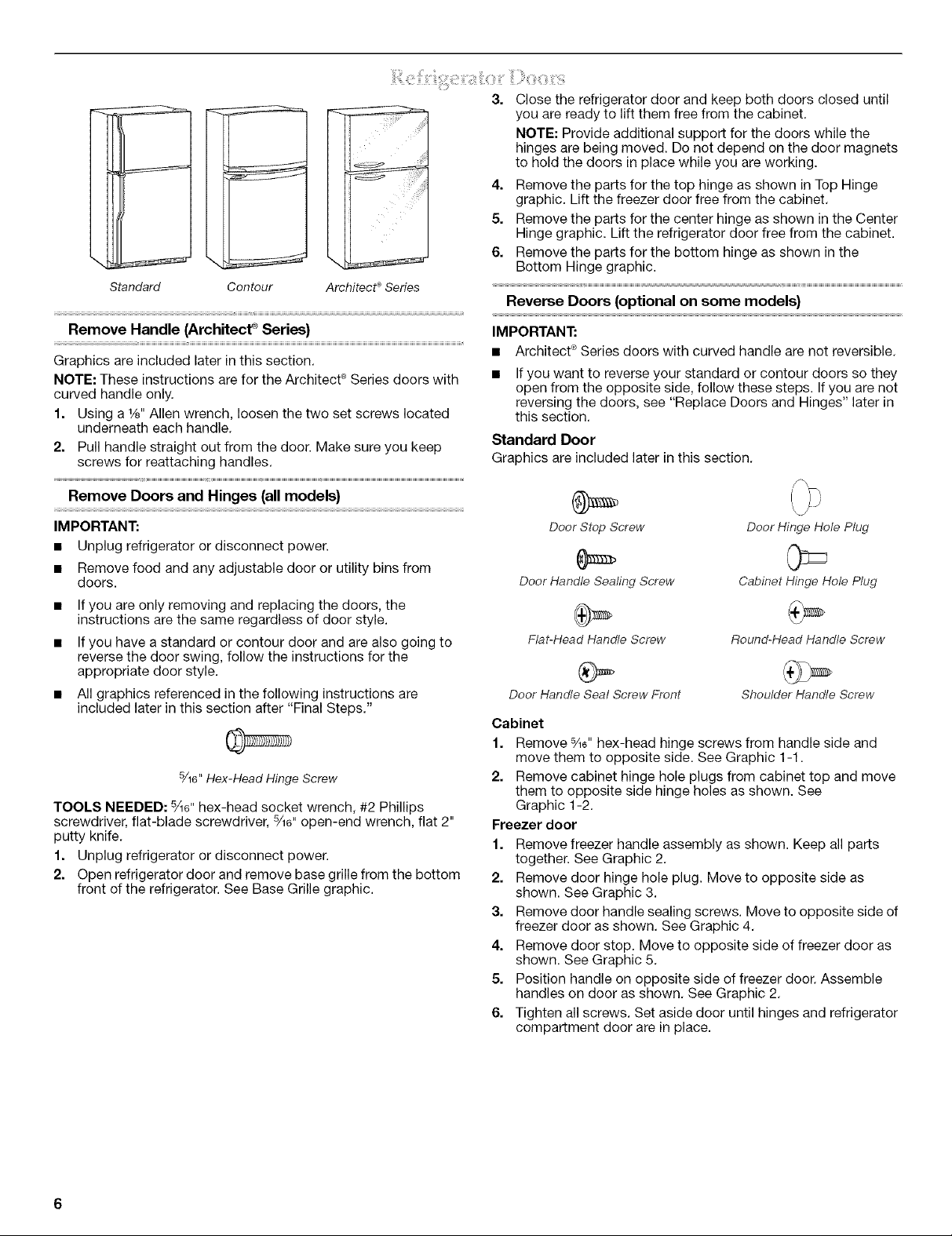
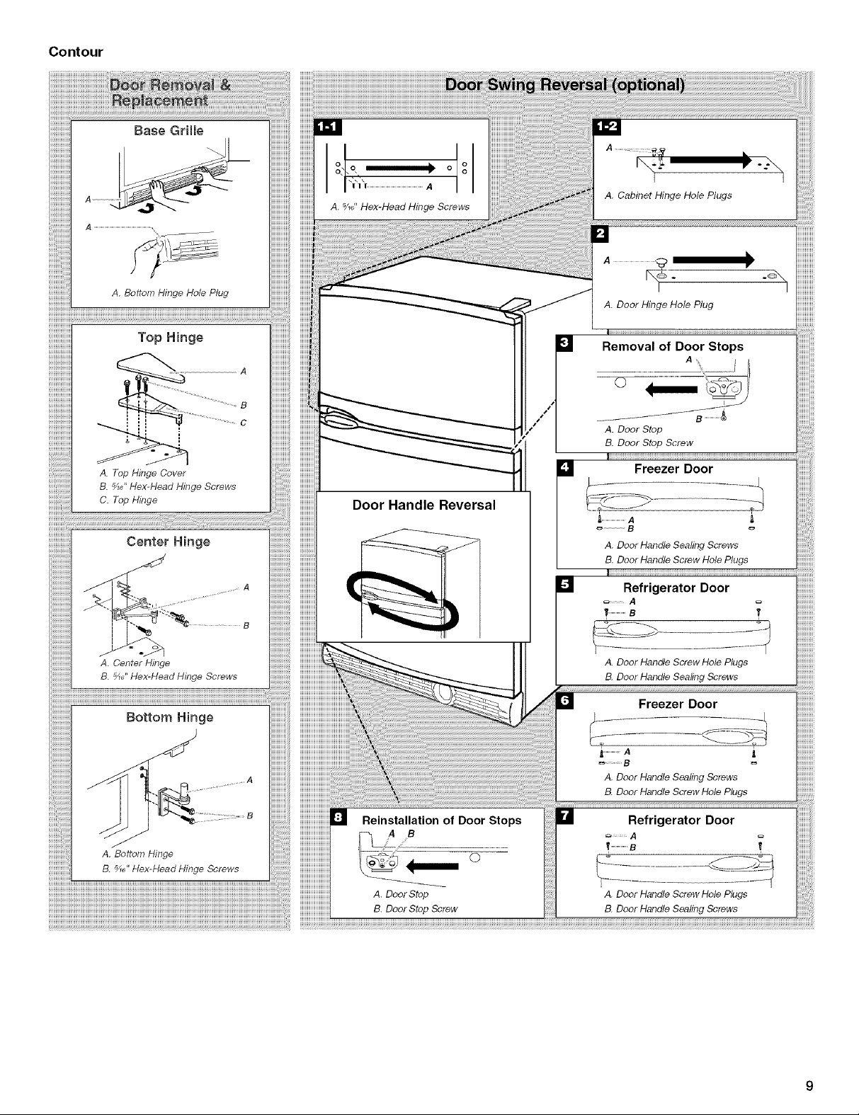
Standard Contour Architectc_Series
3. Close the refrigerator door and keep both doors closed until
you are ready to lift them free from the cabinet.
NOTE: Provide additional support for the doors while the
hinges are being moved. Do not depend on the door magnets
to hold the doors in place while you are working.
4. Remove the parts for the top hinge as shown inTop Hinge
graphic. Lift the freezer door free from the cabinet.
5. Remove the parts for the center hinge as shown in the Center
Hinge graphic. Lift the refrigerator door free from the cabinet.
6. Remove the parts for the bottom hinge as shown in the
Bottom Hinge graphic.
Reverse Doors (optional on some models)
Remove Handle (Architect _ Series)
Graphics are included later in this section.
NOTE: These instructions are for the Architect ®Series doors with
curved handle only.
1. Using a 1/s"Allen wrench, loosen the two set screws located
underneath each handle.
2. Pull handle straight out from the door. Make sure you keep
screws for reattaching handles.
Remove Doors and Hinges (all models}
IMPORTANT:
• Unplug refrigerator or disconnect power.
• Remove food and any adjustable door or utility bins from
doors.
• If you are only removing and replacing the doors, the
instructions are the same regardless of door style.
• If you have a standard or contour door and are also going to
reverse the door swing, follow the instructions for the
appropriate door style.
• All graphics referenced in the following instructions are
included later in this section after "Final Steps."
5/16"Hex-Head Hinge Screw
TOOLS NEEDED: %6" hex-head socket wrench, #2 Phillips
screwdriver, flat-blade screwdriver, %6" open-end wrench, flat 2"
putty knife.
1. Unplug refrigerator or disconnect power.
2. Open refrigerator door and remove base grille from the bottom
front of the refrigerator. See Base Grille graphic.
IMPORTANT:
• Architect ®Series doors with curved handle are not reversible.
If you want to reverse your standard or contour doors so they
open from the opposite side, follow these steps. If you are not
reversing the doors, see "Replace Doors and Hinges" later in
this section.
Standard Door
Graphics are included later in this section.
Door Stop Screw
Door Handle Sealing Screw
Fiat-Head HandleScrew
Door Handle Seal Screw Front
Cabinet
1. Remove %6" hex-head hinge screws from handle side and
move them to opposite side. See Graphic 1-1.
2. Remove cabinet hinge hole plugs from cabinet top and move
them to opposite side hinge holes as shown. See
Graphic 1-2.
Freezer door
1. Remove freezer handle assembly as shown. Keep all parts
together. See Graphic 2.
2. Remove door hinge hole plug. Move to opposite side as
shown. See Graphic 3.
3. Remove door handle sealing screws. Move to opposite side of
freezer door as shown. See Graphic 4.
4. Remove door stop. Move to opposite side of freezer door as
shown. See Graphic 5.
5. Position handle on opposite side of freezer door. Assemble
handles on door as shown. See Graphic 2.
6. Tighten all screws. Set aside door until hinges and refrigerator
compartment door are in place.
Door Hinge Hole Plug
Cabinet Hinge Hole Plug
Round-Head Handle Screw
Shoulder Handle Screw
Refrigeratordoor
1. Removethehandlescrewcover.Dependingonyourmodel,
seeGraphic6-1or6-2.
2. Removethehandlescrews.Keepallpartstogether.See
Graphic6-3.
3. Removedoorhingeholeplugfromtherefrigeratordoor.Move
totheoppositesidehingeholeasshown.SeeGraphic3.
4. Removethedoorhandlesealingscrews.Movetoopposite
sideoftherefrigeratordoor.SeeGraphic4.
5. Removedoorhandlesealscrewfront.Movetooppositeside
ofrefrigeratordoorasshown.SeeGraphic7.
6. Removedoorstop.Movetooppositesideofrefrigeratordoor
asshown.SeeGraphic5.
7. Positiontherefrigeratorhandleontheoppositesideofthe
refrigeratordoor.Drivethetwotopscrews.Then,alignthe
lowerportionofhandleanddrivethebottomscrew.See
Graphic6-3.
8. Tightenallscrews.
9. Replacethescrewcover.Dependingonyourmodel,see
Graphic6-1or6-2.
10.Setasidetherefrigeratordooruntilthebottomhingeis
installedontheproduct.
Contour Door
Graphics are included laterin this section.
Replace Doors and Hinges
NOTE: Graphic may be reversed if door swing is reversed.
1. Replace the parts for the bottom hinge as shown and tighten
screws. See Bottom Hinge graphic. Replace the refrigerator
door.
NOTE: Provide additional support for the doors while the
hinges are being moved. Do not depend on the door magnets
to hold the doors in place while you are working.
2. Assemble the parts for the center hinge as shown and tighten
all screws. See Center Hinge graphic. Replace the freezer
door.
3. Assemble the parts for the top hinge as shown in Top Hinge
graphic. Do not tighten screws completely.
4. Line up the doors so that the bottom of the freezer door aligns
evenly with the top of the refrigerator door. Tighten all screws.
Final Steps
1. Check all holes to make sure that hole plugs and screws are in
place. Reinstall top hinge cover. See Top Hinge graphic.
NOTE: On the left-hand side of the base grille there is a
removable tab which is a bottom hinge hole plug. Break off
the tab from the base grille and insert the bottom hinge hole
plug into the bottom hinge holes. See Base Grille graphic.
2. Replace the base grille. See Base Grille graphic.
Round-Head Door Handle Door Hinge
Handle Screw Screw Hole Plug Hole Plug
Cabinet
1. Remove _1_" hex-head hinge screws from handle side and
move them to opposite side. See Graphic 1-1.
2. Remove cabinet hinge hole plugs from the cabinet top and
move them to opposite side hinge holes as shown in
Graphic 1-2.
Doors
1. Remove door hinge hole plug from top of freezer door. Move
to opposite side as shown in Graphic 2.
2. Remove door stop from both the freezer and refrigerator door.
See Graphic 3.
NOTE: When reversing the door, the freezer handle becomes the
refrigerator door handle and the refrigerator door handle becomes
the freezer handle. See Door Handle Reversal graphic.
3. Remove freezer handle assembly as shown. Keep all parts
together. See Graphic 4.
4. Remove refrigerator handle assembly as shown. Keep all
parts together. See Graphic 5.
5. Rotate and position handle from refrigerator door onto freezer
door and assemble as shown in Graphic 6.
6. Rotate and position handle from freezer door onto refrigerator
door and assemble as shown in Graphic 7.
7. Reinstall door stops to opposite side. See Graphic 8.
Electrical Shock Hazard
Plug into a grounded 3 prong outlet.
Do not remove ground prong,
Do not use an adapter.
Do not use an extension cord.
Failure to follow these instructions can result in death,
fire, or electrica_ shock,
3. Plug in refrigerator or reconnect power.
4. Return all removable door parts to the doors and food to the
product.
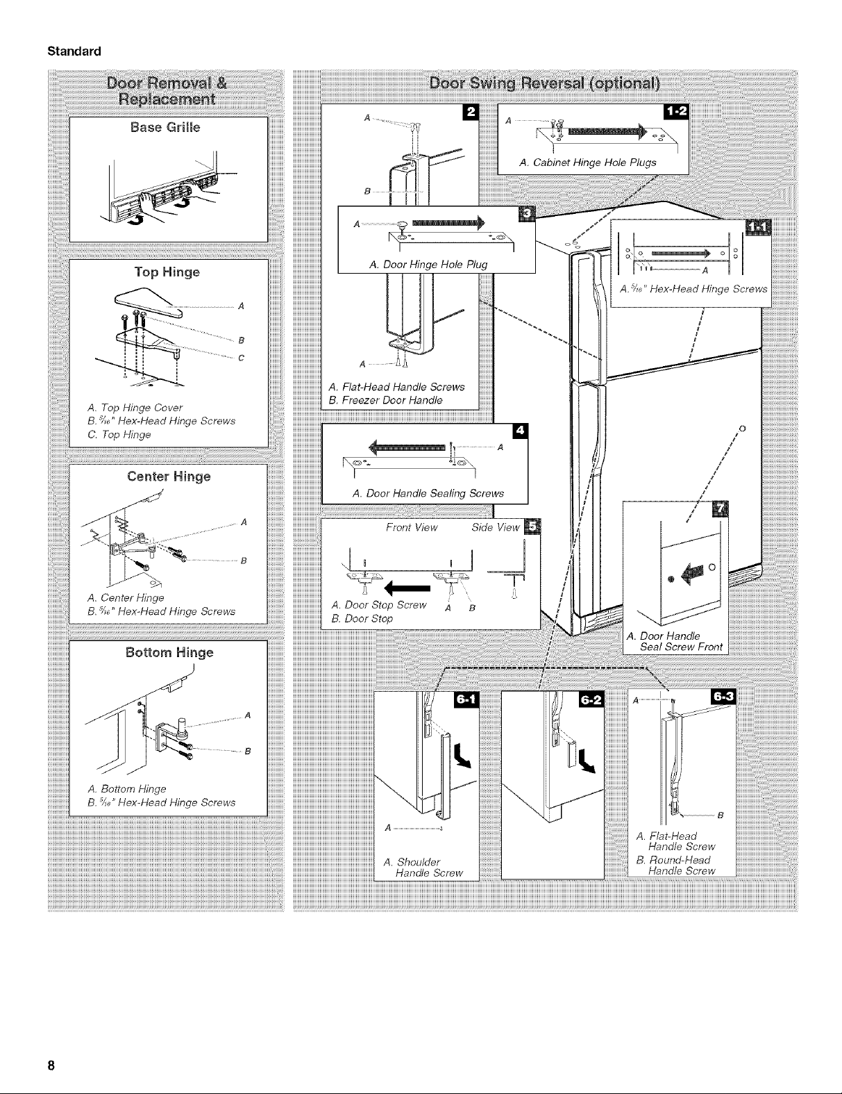
Standard
iiiiiiiiiiiiiiiiiiiiiiiiiii!;!ii
Base Gritte
Center Hinge
B
I Ili
I "_\1
A. Door Hinge Hole Plug
A. Flat-Head Handle Screws
B. Freezer Door Handle
A. Door Handle Sealing Screws
Front View Side View
I I
A. Cabinet Hinge Hole Plugs
A._" Hex-Head Hinge Screws
/
#
/
/
I
0
/
I
/
!
/
i
/
i
A. Center Hinge
B. 5/_,,Hex-Head Hinge Screws
Bottom Hinge
A. Bottom Hinge
B. 5/_,,Hex-Head Hinge Screws
B
A. Door Stop Screw A B
B. Door Stop
B
A ...........................................................
A. Shoulder
Handle Screw
S
A. Door Handle
Seal Screw Front
A. Flat-Head
Handle Screw
B. Round-Head
Handle Screw
Contour
'.....................................................................ooo
A. Cabinet Hinge Hole Plugs
A. ¾_" Hex-Head Hinge Screws
A. Door Hinge Hole Plug
A. Door Step
B. Door Stop Screw
A. Center Hinge
B. _6" HexoHead Hinge Screws
Bottom Binge
A. Bottom Hinge
B. _" Hex-Head Hinge Screws
[] Freezer Door
Door Handle Reversal
............................A
B
A. Door Handle Sealing Screws
B. Door Handle Screw Hole Plugs
Refrigerator Door
A
B
Reinstallation of Door Stops
r
©
T.....................B _'
A. Door Handle Screw Hole Plugs
B. Door Handle Sealing Screws
Freezer Door
_,...................A _,
A. Deer Handle Sealing Screws
B. Door Handle Screw Hole Plugs
Refrigerator Door
A
A. Door Stop
B. Door Stop Screw
A. Door Handle Screw Hole Plugs
B. Door Handle Sealing Screws
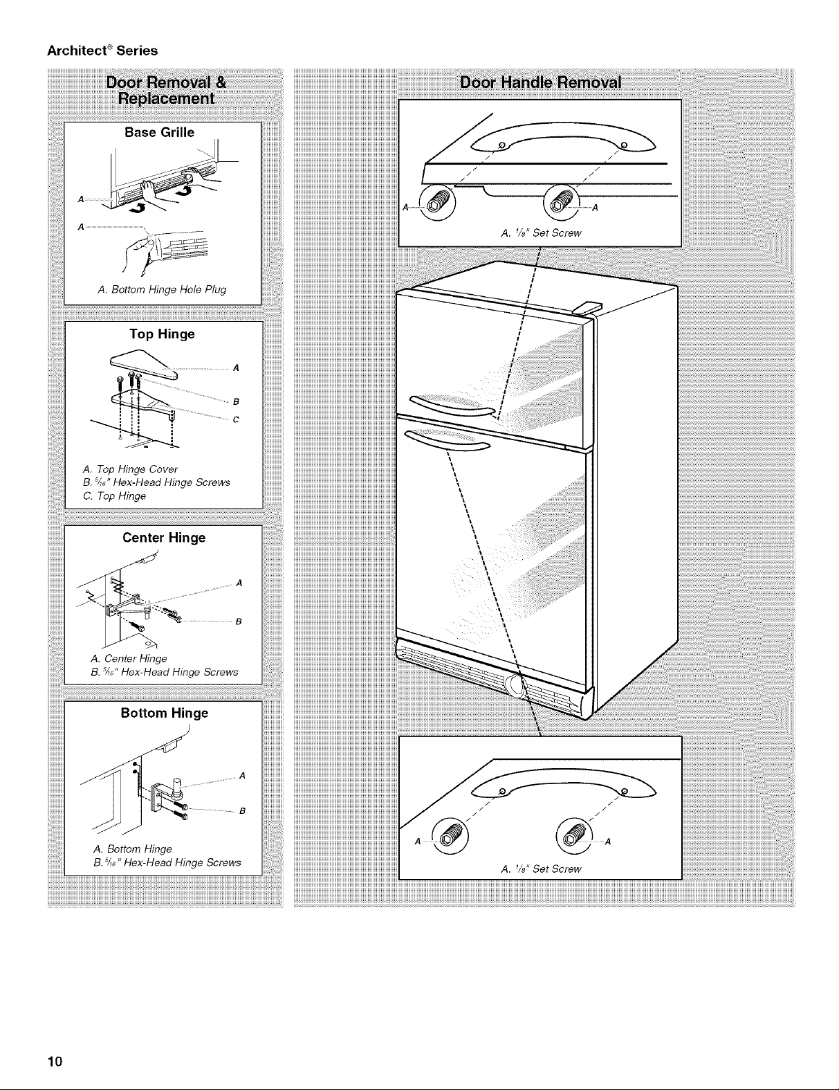
Base Grille
A. Bottom Hinge Hole Plug
/
//
/
A. Top Hinge Cover
B. 5/_e"Hex-Head Hinge Screws
C. Top Hinge
Center Hinge
A. Center Hinge
B. 5/_6"Hex-Head Hinge Screws
Bottom Hinge
A. Bottom Hinge
5
B. _6" Hex-Head Hinge Screws
\
A. 1/8" Set Screw
10
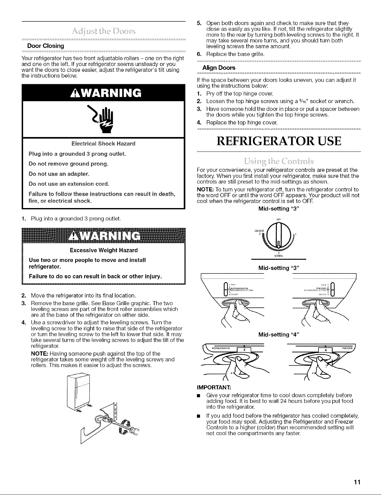
Door Closing
Your refrigerator has two front adjustable rollers - one on the right
and one on the left. Ifyour refrigerator seems unsteady or you
want the doors to close easier, adjust the refrigerator's tilt using
the instructions below.
5. Open both doors again and check to make sure that they
close as easily as you like. If not, tilt the refrigerator slightly
more to the rear by turning both leveling screws to the right. It
may take several more turns, and you should turn both
leveling screws the same amount.
6. Replace the base grille.
Align Doors
If the space between your doors looks uneven, you can adjust it
using the instructions below:
1. Pry off the top hinge cover.
2. Loosen the top hinge screws using a 5/16"socket or wrench.
3. Have someone hold the door in place or put a spacer between
the doors while you tighten the top hinge screws.
4. Replace the top hinge cover.
E_ectrical Shock Hazard
P_ug into a grounded 3 prong outlet.
Do not remove ground prong.
Do not use an adapter.
Do not use an extension cord.
Failure to follow these instructions can result in death,
fire, or electrical shock.
1. Plug into a grounded 3 prong outlet.
Excessive Weight Hazard
Use two or more people to move and install
refrigerator.
Failure to do so can result in back or other injury.
2,
Move the refrigerator into its final location.
3.
Remove the base grille. See Base Grille graphic. The two
leveling screws are part of the front roller assemblies which
are at the base of the refrigerator on either side.
4,
Use a screwdriver to adjust the leveling screws. Turn the
leveling screw to the right to raise that side of the refrigerator
or turn the leveling screw to the left to lower that side. It may
take several turns of the leveling screws to adjust the tilt of the
refrigerator.
NOTE: Having someone push against the top of the
refrigerator takes some weight off the leveling screws and
rollers. This makes it easier to adjust the screws.
REFRIGERATOR USE
For your convenience, your refrigerator controls are preset at the
factory. When you first install your refrigerator, make sure that the
controls are still preset to the mid-settings as shown.
NOTE: To turn your refrigerator off, turn the refrigerator control to
the word OFF or until the word OFF appears. Your product will not
cool when the refrigerator control is set to OFR
Mid-setting "3"
OFF
5 1
C0LgESG
N0_3t_L
IMPORTANT:
Give your refrigerator time to cool down completely before
adding food. It is best to wait 24 hours before you put food
into the refrigerator.
If you add food before the refrigerator has cooled completely,
your food may spoil. Adjusting the Refrigerator and Freezer
Controls to a higher (colder) than recommended setting will
not cool the compartments any faster.
11
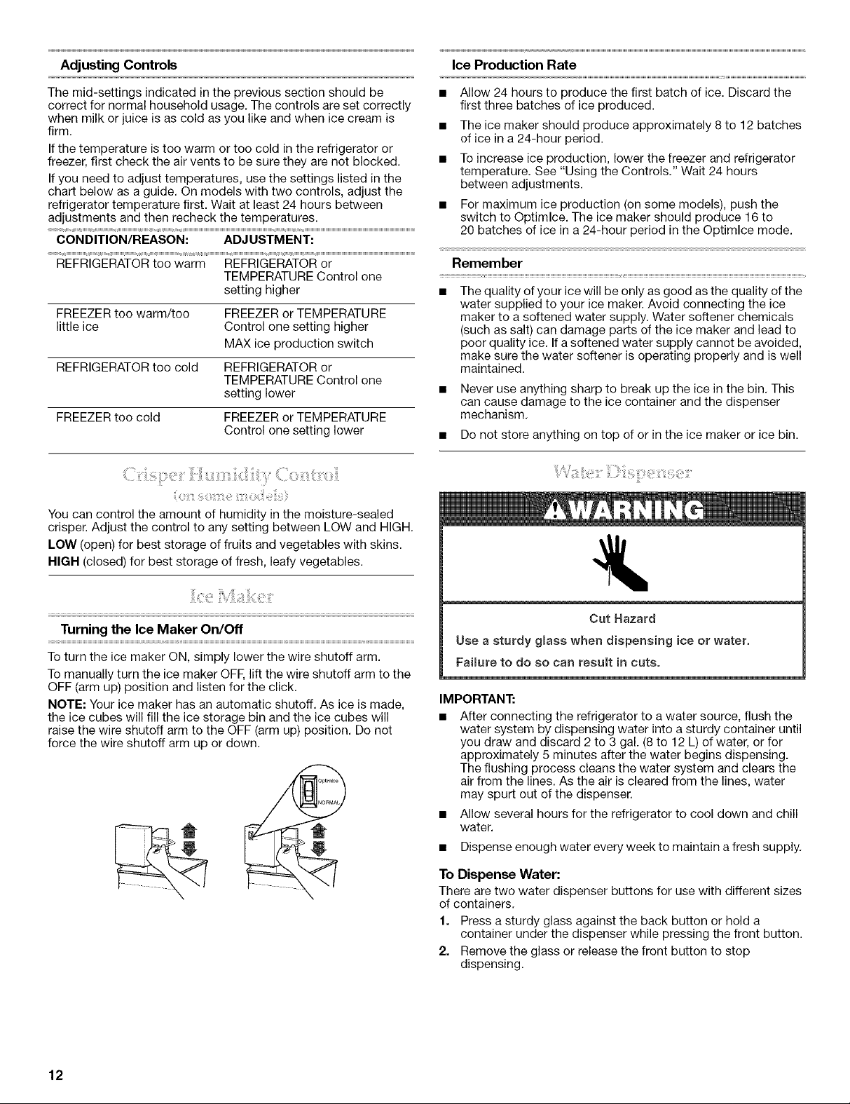
AdjustingControls IceProductionRate
The mid-settings indicated in the previous section should be
correct for normal household usage. The controls are set correctly
when milk or juice is as cold as you like and when ice cream is
firm.
If the temperature is too warm or too cold in the refrigerator or
freezer, first check the air vents to be sure they are not blocked.
If you need to adjust temperatures, use the settings listed in the
chart below as a guide. On models with two controls, adjust the
refrigerator temperature first. Wait at least 24 hours between
adjustments and then recheck the temperatures.
CONDITION/REASON: ADJUSTMENT:
REFRIGERATOR too warm REFRIGERATOR or
TEMPERATURE Control one
setting higher
FREEZER too warm/too FREEZER or TEMPERATURE
little ice Control one setting higher
MAX ice production switch
REFRIGERATOR too cold REFRIGERATOR or
TEMPERATURE Control one
setting lower
FREEZER too cold FREEZER or TEMPERATURE
Control one setting lower
{
You can control the amount of humidity in the moisture-sealed
crisper. Adjust the control to any setting between LOW and HIGH.
LOW (open) for best storage of fruits and vegetables with skins.
HIGH (closed) for best storage of fresh, leafy vegetables.
• Allow 24 hours to produce the first batch of ice. Discard the
first three batches of ice produced.
• The ice maker should produce approximately 8to 12 batches
of ice in a 24-hour period.
• To increase ice production, lower the freezer and refrigerator
temperature. See "Using the Controls." Wait 24 hours
between adjustments.
• For maximum ice production (on some models), push the
switch to Optimlce. The ice maker should produce 16 to
20 batches of ice in a 24-hour period in the Optimlce mode.
Remember
• The quality of your ice will be only as good as the quality of the
water supplied to your ice maker. Avoid connecting the ice
maker to a softened water supply. Water softener chemicals
(such as salt) can damage parts of the ice maker and lead to
poor quality ice. If a softened water supply cannot be avoided,
make sure the water softener is operating properly and is well
maintained.
• Never use anything sharp to break up the ice in the bin. This
can cause damage to the ice container and the dispenser
mechanism.
• Do not store anything on top of or in the ice maker or ice bin.
!:
Turning the Ice Maker On/Off
To turn the ice maker ON, simply lower the wire shutoff arm.
To manually turn the ice maker OFF,lift the wire shutoff arm to the
OFF (arm up) position and listen for the click.
NOTE: Your ice maker has an automatic shutoff. As ice is made,
the ice cubes will fill the ice storage bin and the ice cubes will
raise the wire shutoff arm to the OFF (arm up) position. Do not
force the wire shutoff arm up or down.
Cut Hazard
Use a sturdy glass when dispensing ice or water.
Failure to do so can result in cuts.
IMPORTANT:
• After connecting the refrigerator to a water source, flush the
water system by dispensing water into a sturdy container until
you draw and discard 2 to 3 gal. (8 to 12 L) of water, or for
approximately 5 minutes after the water begins dispensing.
The flushing process cleans the water system and clears the
air from the lines. As the air is cleared from the lines, water
may spurt out of the dispenser.
Allow several hours for the refrigerator to cool down and chill
water.
Dispense enough water every week to maintain a fresh supply.
To Dispense Water:
There are two water dispenser buttons for use with different sizes
of containers.
1. Press a sturdy glass against the back button or hold a
container under the dispenser while pressing the front button.
2. Remove the glass or release the front button to stop
dispensing.
12
';_iii&i_;i!ii:;_:ii!!i_i_i_i¸¸!::;_ii!iii_:iii:_ii_i:iio_ii_ii'i'!iiii_ii!_!?'!i!i_i/;E:_ii:i_:_i_
NOTE: Do not use with water that is microbiologically unsafe
or of unknown quality without adequate disinfection before or
after the system. Systems certified for cyst reduction may be
used on disinfected waters that may contain filterable cysts.
Water Filter Status Light (on some models)
The water filter status light will help you know when to change
your water filter. The light will change from green to yellow. This
tells you that it is almost time to change the filter. It is
recommended that you replace the water filter when the status
light changes to red OR water flow to your water dispenser or ice
maker decreases noticeably.
After changing the water filter, reset the water filter status light.
The status light will change from red to green when the system is
reset.
Non-indicator Water Filter (on some models)
If your refrigerator does not have the status light, you should
change the water filter every 6 to 9 months depending upon your
usage. If the water flow to the water dispenser or ice maker
decreases noticeably before 6 months have passed, replace the
water filter more often.
Using the Dispenser Without the Water Filter
To Clean Your Refrigerator:
NOTE: Do not use abrasive or harsh cleaners such as window
sprays, scouring cleansers, flammable fluids, cleaning waxes,
concentrated detergents, bleaches or cleansers containing
petroleum products on plastic parts, interior and door liners or
gaskets. Do not use paper towels, scouring pads, or other harsh
cleaning tools.
1. Unplug refrigerator or disconnect power.
2. Hand wash, rinse, and dry removable parts and interior
surfaces thoroughly. Use a clean sponge or soft cloth and a
mild detergent in warm water.
3. Wash stainless steel and painted metal exteriors with a clean
sponge or soft cloth and a mild detergent in warm water.
4. There is no need for routine condenser cleaning in normal
home operating environments. If the environment is
particularly greasy or dusty, or there is significant pet traffic in
the home, the condenser should be cleaned every 2 to
3 months to ensure maximum efficiency.
If you need to clean the condenser:
• Removethe base grille.
• Use a vacuum cleaner with a soft brush to clean the grille,
the open areas behind the grille and the front surface area
of the condenser.
• Replace the base grille when finished.
5. Plug in refrigerator or reconnect power.
You can run the dispenser without a water filter. Your water will not
be filtered.
1. Remove the water filter.
2. Slide the cap off the end of the filter and replace the cap in the
base grille.
IMPORTANT: Do not discard the cap. It is part of your
refrigerator. Keep the cap to use with the replacement filter.
3. Turn the cap until it is firmly in position.
REFRIGERATOR CARE
Explosion Hazard
Use nonflammable cleanero
Failure to do so can result in death, explosion, or fire.
NOTE: Not all bulbs will fit your refrigerator. Be sure to replace the
bulb with one of the same size, shape, and wattage.
1. Unplug refrigerator or disconnect power.
2. Remove the bulb from behind the control panel in the
refrigerator or from behind the light shield in the freezer (on
some models). Replace it with a bulb of the same wattage.
3. Plug in refrigerator or reconnect power.
Both the refrigerator and freezer sections defrost automatically.
However, clean both sections about once a month to prevent
odors from building up. Wipe up spills immediately.
IMPORTANT: Because air circulates between both sections, any
odors formed in one section will transfer to the other. You must
thoroughly clean both sections to eliminate odors. To prevent
odor transfer and drying out of food, wrap or cover foods tightly.
13
TROUBLESHOOTING
Trythe solutions suggested here first in order to avoid the cost of an unnecessary service call.
The doors will not close completely
The refrigerator will not operate
• Power cord unplugged? Plug into a grounded 3 prong outlet,
• Is outlet working? Plug in a lamp to see if the outlet is
working,
• Household fuse blown or circuit breaker tripped? Replace
the fuse or reset the circuit breaker.
Are controls on? Make sure the refrigerator controls are on.
See "Using the Controls."
New installation? Allow 24 hours following installation for the
refrigerator to cool completely.
NOTE: Adjusting the temperature controls to coldest setting
will not cool either compartment more quickly.
The motor seems to run too much
Your new refrigerator may run longer than your old one due to its
high-efficiency compressor and fans. The unit may run even
longer if the room is warm, a large food load is added, doors are
opened often, or if the doors have been left open.
The refrigerator seems noisy
Refrigerator noise has been reduced over the years. Due to this
reduction, you may hear intermittent noises from your new
refrigerator that you did not notice from your old model. Below are
listed some normal sounds with explanations.
• Buzzing - heard when the water valve opens to fill the ice
maker
• Pulsating - fans/compressor adjusting to optimize
performance
• Hissing/Rattling - flow of refrigerant, movement of water
lines, or from items placed on top of the refrigerator
• Sizzling/Gurgling - water dripping on the heater during
defrost cycle
• Popping - contraction/expansion of inside walls, especially
during initial cool-down
• Water running - may be heard when water melts during the
defrost cycle and runs into the drain pan
• Creaking/Cracking - occurs as ice is being ejected from the
ice maker mold,
• Door blocked open? Move food packages away from door.
• Bin or shelf in the way? Push bin or shelf back in the correct
position.
The doors are difficult to open
• Gaskets dirty or sticky? Clean gaskets and contact surfaces
with mild soap and warm water. Rinse and dry with soft cloth,
i
Temperature is too warm
• New installation? Allow 24 hours following installation for the
refrigerator to cool completely.
• Door(s) opened often or left open? Allows warm air to enter
refrigerator. Minimize door openings and keep doors fully
closed.
• Large load of food added? Allow several hours for
refrigerator to return to normal temperature.
• Controls set correctly for the surrounding conditions?
Adjust the controls a setting colder. Check temperature in
24 hours. See "Using the Controls."
There is interior moisture buildup
NOTE: Some moisture build-up is normal.
• Humid room? Contributes to moisture build-up.
• Door(s) opened often or left open? Allows humid air to enter
refrigerator. Minimize door openings and keep doors fully
closed.
The ice maker is not producing ice or not enough ice
• Refrigerator connected to a water supply and the supply
shutoff valve turned on? Connect refrigerator to water
supply and turn water shutoff valve fully open.
• Kink in the water source line? A kink in the line can reduce
water flow. Straighten the water source line.
• Ice maker turned on? Make sure wire shutoff arm or switch
(depending on model) is in the ON position.
14
• New installation? Wait 24 hours after ice maker installation
for ice production to begin. Wait 72 hours for full ice
production.
• Freezer door closed completely? Firmly close the freezer
compartment door. If the freezer compartment door will not
close all the way, see "The doors will not close completely."
• Large amount of ice recently removed? Allow 24 hours for
ice maker to produce more ice.
• Ice cube jammed in the ice maker ejector arm?
Remove ice from the ejector arm with a plastic utensil.
• Water filter installed on the refrigerator? Remove filter and
operate ice maker. If ice volume improves, then the filter may
be clogged or incorrectly installed. Replace filter or reinstall it
correctly.
• Reverse osmosis water filtration system connected to
your cold water supply? This can decrease water pressure.
See "Water Supply Requirements."
The ice cubes are hollow or small
NOTE: This is an indication of low water pressure.
• Water shutoff valve not fully open? Turn the water shutoff
valve fully open.
• Kink in the water source line? A kink in the line can reduce
water flow. Straighten the water source line.
• Water filter installed on the refrigerator? Remove filter and
operate ice maker. If ice quality improves, then the filter may
be clogged or incorrectly installed. Replace filter or reinstall it
correctly.
• Reverse osmosis water filtration system connected to
your cold water supply? This can decrease water pressure.
See "Water Supply Requirements."
• Questions remain regarding water pressure? Call a
licensed, qualified plumber.
Off-taste, odor or gray color in the ice
• New plumbing connections? New plumbing connections
can cause discolored or off-flavored ice.
• Ice stored too long? Discard ice. Wash ice bin. Allow
24 hours for ice maker to make new ice.
• Odor transfer from food? Use airtight, moisture proof
packaging to store food.
• Are there minerals (such as sulfur) in the water? A water
filter may need to be installed to remove the minerals.
• Water filter installed on the refrigerator? Gray or dark
discoloration in ice indicates that the water filtration system
needs additional flushing. Flush the water system before using
a new water filter. Replace water filter when indicated. See
"Water Filtration System."
The water dispenser will not operate properly
• Refrigerator connected to a water supply and the supply
shutoff valve turned on? Connect refrigerator to water
supply and turn water shutoff valve fully open.
• Kink in the water source line? Straighten the water source
line.
• New installation? Flush and fill the water system. See "Water
Dispenser."
• Is the water pressure at least 30 psi? The water pressure to
the home determines the flow from the dispenser. See "Water
Supply Requirements."
• Water filter installed on the refrigerator? Remove filter and
operate dispenser. If water flow increases, the filter may be
clogged or incorrectly installed. Replace filter or reinstall it
correctly.
• Reverse osmosis water filtration system connected to
your cold water supply? This can decrease water pressure.
See "Water Supply Requirements."
Water is dripping from the dispenser
NOTE: One or two drops of water after dispensing is normal.
• Glass not being held under the dispenser long enough?
Hold the glass under the dispenser 2 to 3 seconds after
releasing the dispenser lever.
• New installation? Flush the water system. See "Water
Dispenser."
• Recently changed water filter? Flush the water system. See
"Water Dispenser."
Water from the dispenser is warm
NOTE: Water from the dispenser is only chilled to 50°F (10°C).
• New installation? Allow 24 hours after installation for the
water supply to cool completely.
• Recently dispensed large amount of water? Allow 24 hours
for water supply to cool completely.
• Water not been recently dispensed? The first glass of water
may not be cool. Discard the first glass of water.
• Refrigerator connected to a cold water pipe? Make sure
the refrigerator is connected to a cold water pipe. See "Water
Supply Requirements."
15
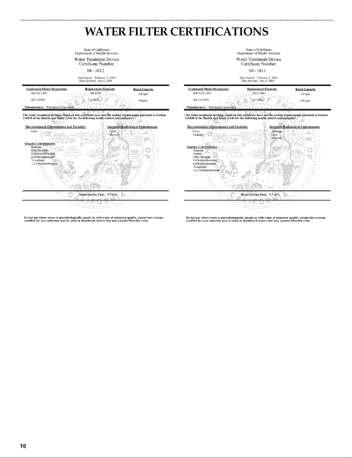
WATER FILTER CERTIFICATIONS
State of CalJfolnia
Deparlment of ltealth Services
Water Treatment Device
Certificate Number
1)4- 1612
Date lss_ed: _ebruat_ 2, 2(KM
Dire Revised: July 6, 2004
Trademark/Model Designation Replacement Elements Rated C_
WF-NL120V NLI20V 120 gals
....... _.2oo{
3,1anufacturer: VChM
116830 of the Health and
3/licrohiolo_iCai _ii_taraiaants and Turbidit
None
ursuant to Section
' ¸:¸:/17!!¸¸¸I¸¸I¸¸¸¸'!:I::i;¸¸¸¸:
Do not use where water is microbiologically unsafe or with water of unknowR quali_', except that systems
certified lbr cyst redt*ction may be ttsed on disinfected waters that may contain lilter able ¢_,sls.
State of California
Depaltmen| of Health Services
Water Treaunent Device
Certificate Number
04- 1611
Dale Revise July ,.7004
TradeaaarkJModel Designation Replacement Elements Rated ('a acp_
WP-NLCI20V NLC170V /20 gal_
VIM C_00V LCg00 200 gol_
_anufacturer: _:_po_] Corpor_or
The water treatmenl t*ev_ce_) listed on this certificate have met fhe testing requirements pursuant to Seelion
116830 of the Ilealth and S_fetv Code far th_ follawlng health related contaminant_'
IVllcrobiologieal Cantaminanls and Turbidity
Cysts
_rmm_3
Organic Cnntaminants
t3ei_/ene
_.drm
ioxaonene
24-tnchlorohen7ene
Raled Service glo¢_l 05gpm
Do not use where _ater is microbiologieally unsai_ or with water of unknown qnality_ except thai systems
certified _r cyst reduction may be used on disin_cted waters that may contain filterable cysts.
lnor _a nic_Radlolo_ic al Contaminanls
16
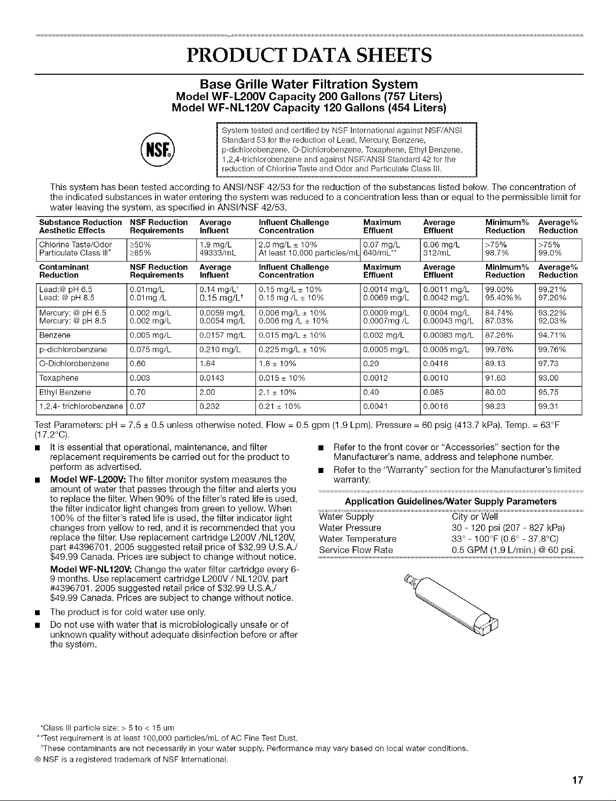
PRODUCT DATA SHEETS
Base Grille Water Filtration System
Model WF-L200V Capacity 200 Gallons (757 Liters)
Model WF-NL120V Capacity 120 Gallons (454 Liters)
System tested and certified by NSF International against NSF/ANSi
Standard 53 for the reduction of Lead, Mercury, Benzene,
p-dichlorobenzene, O-Dichlorobenzene, Toxaphene, Ethyl Benzene,
1,2,4-tricMorobenzene and against NSF/ANSI Standard 42 for the
reduction of Chlorine Taste and Odor and Particulate Class Ill=
This system has been tested according to ANSl/NSF 42/53 for the reduction of the substances listed below. The concentration of
the indicated substances in water entering the system was reduced to a concentration less than or equal to the permissible limit for
water leaving the system, as specified in ANSI/NSF 42/53.
Substance Reduction NSF Reduction Average Influent Challenge Maximum Average Minimum% Average%
Aesthetic Effects Requirements Influent Concentration Effluent Effluent Reduction Reduction
Chlorine Taste/Odor _>50% 1.9 mg/L 2.0 mg/L _+10% 0.07 mg/L 0.06 mg/L >75% >75%
49333/mL 312/mL 98.7% 99.0%Part cu ate C ass * _>85% At east 10,000 par_ c es/mL 640/mL**
Contaminant NSF Reduction Average Influent Challenge Maximum Average Minimum% Average%
Reduction Requirements Influent Concentration Effluent Effluent Reduction Reduction
Lead:@ pH 6.5 0.Olmg/L 0.14 mg/L _ 0.15 mg/L _+10% 0.0014 mg/L 0.0011 mg/L 99.00% 99.21%
Lead: @pH 8.5 0.01 mg/L 0.15 mg/L t 0.15 mg/L _+10% 0.0069 mg/L 0.0042 mg/L 95.40%% 97.20%
Mercury: @pH 6.5 0.002 mg/L 0.0059 mg/L 0.006 mg/L _+10% 0.0009 mg/L 0.0004 mg/L 84.74% 93.22%
Mercury: @pH 8.5 0.002 mg/L 0.0054 mg/L 0.006 mg/L _+10% 0.0007mg/L 0.00043 mg/L 87.03% 92.03%
Benzene 0.005 mg/L 0.0157 mg/L 0.015 mg/L _+10% 0.002 mg/L 0.00083 mg/L 87.26% 94.71%
p-dichlorobenzene 0.075 mg/L 0.210 mg/L 0.225 mg/L _+10% 0.0005 mg/L 0.0005 mg/L 99.76% 99.76%
O-Dichlorobenzene 0.60 1.84 1.8 _+10% 0.20 0.0418 89.13 97.73
Toxaphene 0.003 0.0143 0.015 _+10% 0.0012 0.0010 91.60 93.00
Ethyl Benzene 0.70 2.00 2.1 _+10% 0.40 0.085 80.00 95.75
1,2,4- trichlorobenzene 0.07 0.232 0.21 _+10% 0.0041 0.0016 98.23 99.31
Test Parameters: pH = 7.5 + 0.5 unless otherwise noted. Flow = 0.5 gpm (1.9 Lpm). Pressure = 60 psig (413.7 kPa). Temp. = 63°F
(17.2°C).
• It is essential that operational, maintenance, and filter
replacement requirements be carried out for the product to
perform as advertised.
• Model WF-L2OOV: The filter monitor system measures the
• Refer to the front cover or "Accessories" section for the
Manufacturer's name, address and telephone number.
• Refer to the "Warranty" section for the Manufacturer's limited
warranty.
amount of water that passes through the filter and alerts you
to replace the filter. When 90% of the filter's rated life is used,
the filter indicator light changes from green to yellow. When
100% of the filter's rated life is used, the filter indicator light
changes from yellow to red, and it is recommended that you
replace the filter. Use replacement cartridge L200V/NL120V,
part #4396701. 2005 suggested retail price of $32.99 U.S.A./
$49.99 Canada. Prices are subject to change without notice.
Application Guidelines/Water Supply Parameters
Water Supply City or Well
Water Pressure 30 - 120 psi (207 - 827 kPa)
Water Temperature 33 ° - 100°F (0.6 ° - 37.8°C)
Service Flow Rate 0.5 GPM (1.9 L/min.) @60 psi.
Model WF-NL120V: Change the water filter cartridge every 6-
9 months. Use replacement cartridge L200V/NL120V, part
#4396701. 2005 suggested retail price of $32.99 U.S.A./
$49.99 Canada. Prices are subject to change without notice.
• The product is for cold water use only.
• Do not use with water that is microbiologically unsafe or of
unknown quality without adequate disinfection before or after
the system.
*Class IIIparticle size: > 5 to < 15 um
**Test requirement is at least 100,000 particles/mL of AC Fine Test Dust.
tThese contaminants are not necessarily in your water supply. Performance may vary based on local water conditions.
® NSF is a registered trademark of NSF International.
17
 Loading...