

KitchenAid KSIB900ESS1, KSIB900ESS2 Installation Guide

INSTALLATION INSTRUCTIONS
IMPORTANT:
Save for local electrical inspector's use.
IMPORTANT :
À conserver pour consultation par l'inspecteur local des installations électriques.
W10744014B
SLIDE-IN ELECTRIC RANGES
INSTRUCTIONS D’INSTALLATION DES CUISINIÈRES
ÉLECTRIQUES ENCASTRABLES
Table of Contents/Table des matières
RANGE SAFETY .............................................................................2
INSTALLATION REQUIREMENTS................................................3
Tools and Parts ............................................................................3
Location Requirements................................................................3
Electrical Requirements - U.S.A. Only.........................................6
Electrical Requirements - Canada Only.......................................7
INSTALLATION INSTRUCTIONS..................................................8
Unpack Range..............................................................................8
Install Anti-Tip Bracket.................................................................8
Adjust Leveling Legs....................................................................9
Level Range................................................................................10
Verify Anti-Tip Bracket Is Installed and Engaged ......................10
Remove/Replace Drawer...........................................................11
Oven Door ..................................................................................11
Complete Installation .................................................................12
SÉCURITÉ DE LA CUISINIÈRE ...................................................14
EXIGENCES D’INSTALLATION...................................................15
Outillage et pièces......................................................................15
Exigences d’emplacement.........................................................15
Spécifications de l’installation électrique...................................18
INSTRUCTIONS D’INSTALLATION.............................................19
Déballage de la cuisinière ..........................................................19
Installation de la bride antibasculement ....................................19
Réglage des pieds de nivellement .............................................20
Réglage de l’aplomb de la cuisinière.........................................21
Vérifier que la bride antibasculement est bien installée
et engagée..................................................................................21
Dépose et réinstallation du tiroir ................................................22
Porte du four...............................................................................22
Achever l’installation ..................................................................23
RANGE SAFETY
You can be killed or seriously injured if you don't immediately
You
can be killed or seriously injured if you don't
follow
All safety messages will tell you what the potential hazard is, tell you how to reduce the chance of injury, and tell you what can
happen if the instructions are not followed.
Your safety and the safety of others are very important.
We have provided many important safety messages in this manual and on your appliance. Always read and obey all safety
messages.
This is the safety alert symbol.
This symbol alerts you to potential hazards that can kill or hurt you and others.
All safety messages will follow the safety alert symbol and either the word “DANGER” or “WARNING.”
These words mean:
follow instructions.
instructions.
DANGER
WARNING
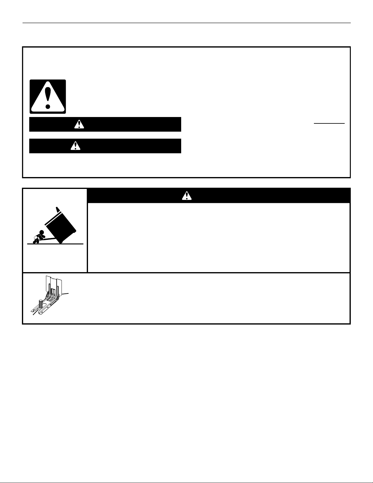
Tip Over Hazard
A child or adult can tip the range and be killed.
Install anti-tip bracket to floor or wall per installation instructions.
Slide range back so rear range foot is engaged in the slot of the anti-tip bracket.
Re-engage anti-tip bracket if range is moved.
Do not operate range without anti-tip bracket installed and engaged.
Failure to follow these instructions can result in death or serious burns to children and adults.
Anti-Tip
Bracket
To verify the anti-tip bracket is installed and engaged:
• Slide range forward.
• Look for the anti-tip bracket securely attached to floor or wall.
• Slide range back so rear range foot is under anti-tip bracket.
• See installation instructions for details.
Range Foot
WARNING
2

INSTALLATION REQUIREMENTS
Tools and Parts
Gather the required tools and parts before starting installation.
Read and follow the instructions provided with any tools listed
here.
Tools Needed
■ Tape m e a s ure
■ Flat-blade screwdriver
■ Phillips screwdriver
■ Level
■ Hand or electric drill
■ Wrench or pliers
■ Marker or pencil
Parts Supplied
Check that all parts are included.
■ #10 x 1⁵⁄₈" (4.1 cm) screws (for mounting anti-tip bracket) (2)
■ Anti-tip bracket (inside oven cavity)
Anti-tip bracket must be securely mounted to the back wall or
floor. Thickness of flooring may require longer screws to
anchor bracket to subfloor. Longer screws are available from
your local hardware store.
■ Oven racks (3)
Optional Parts
To purchase these or any other accessories, please reference the
“Accessories” section of the User Guide for contact information.
■ Side Trim Kits:
⁵⁄₈" (1.7 cm) White - Order Part Number W10675027
⁵⁄₈" (1.7 cm) Black - Order Part Number W10675026
⁵⁄₈" (1.7 cm) Stainless Steel - Order Part Number W10675028
1¹⁄₈" (2.9 cm) White - Order Part Number W10731885
1¹⁄₈" (2.9 cm) Black - Order Part Number W10731886
1¹⁄₈" (2.9 cm) Stainless Steel - Order Part Number
W10731887
■ Backsplash Kits:
High 6" (15.2 cm) White - Order Part Number W10655448
High 6" (15.2 cm) Black - Order Part Number W10655449
High 6" (15.2 cm) Stainless Steel - Order Part Number
W10655450
■ Masking tape
■ ¼" (6.4 mm) drive ratchet
■ ¼" (6.4 mm) nut driver
■ ³⁄₈" (9.5 mm) and ⁵⁄₁₆" (8 mm)
nut driver
■ ¹⁄₈" (3.2 mm) drill bit (for
wood floors)
■ Tin snips or large wire
cutters (for cutting ground
strap if necessary)
Location Requirements
IMPORTANT: Observe all governing codes and ordinances.
■ It is the installer’s responsibility to comply with installation
clearances specified on the model/serial/rating plate. The
model/serial/rating plate is located behind the oven door on
the top right-hand side of the oven frame.
■ The range should be located for convenient use in the
kitchen.
■ Recessed installations must provide complete enclosure of
the sides and rear of the range.
■ To eliminate the risk of burns or fire by reaching over the
heated surface units, cabinet storage space located above
the surface units should be avoided. If cabinet storage is to
be provided, the risk can be reduced by installing a range
hood or microwave hood combination that projects
horizontally a minimum of 5" (12.7 cm) beyond the bottom of
the cabinets.
■ All openings in the wall or floor where range is to be installed
must be sealed.
■ Cabinet opening dimensions that are shown must be used.
Given dimensions are minimum clearances.
■ The anti-tip bracket must be installed. To install the anti-tip
bracket shipped with the range, see “Install Anti-Tip Bracket”
section.
■ Grounded electrical supply is required. See the appropriate
“Electrical Requirements” section.
■ Contact a qualified floor covering installer to check that the
floor covering can withstand at least 200°F (93°C).
■ Use an insulated pad or ¼" (0.64 cm) plywood under range if
installing range over carpeting.
IMPORTANT: To avoid damage to your cabinets, check with your
builder or cabinet supplier to make sure that the materials used
will not discolor, delaminate or sustain other damage. This oven
has been designed in accordance with the requirements of UL
and CSA International and complies with the maximum allowable
wood cabinet temperatures of 194°F (90°C).
3
Mobile Home - Additional Installation Requirements
B
D
A
F
E
C
The installation of this range must conform to the Manufactured
Home Construction and Safety Standard, Title 24 CFR, Part 3280
(formerly the Federal Standard for Mobile Home Construction
and Safety, Title 24, HUD Part 280). When such standard is not
applicable, use the Standard for Manufactured Home
Installations, ANSI A225.1/NFPA 501A or with local codes.
In Canada, the installation of this range must conform with the
current standards CAN/CSA-A240-latest edition, or with local
codes.
Mobile Home Installations Require:
■ When this range is installed in a mobile home, it must be
secured to the floor during transit. Any method of securing
the range is adequate as long as it conforms to the standards
listed above.
■ Four-wire power supply cord or cable must be used in a
mobile home installation.
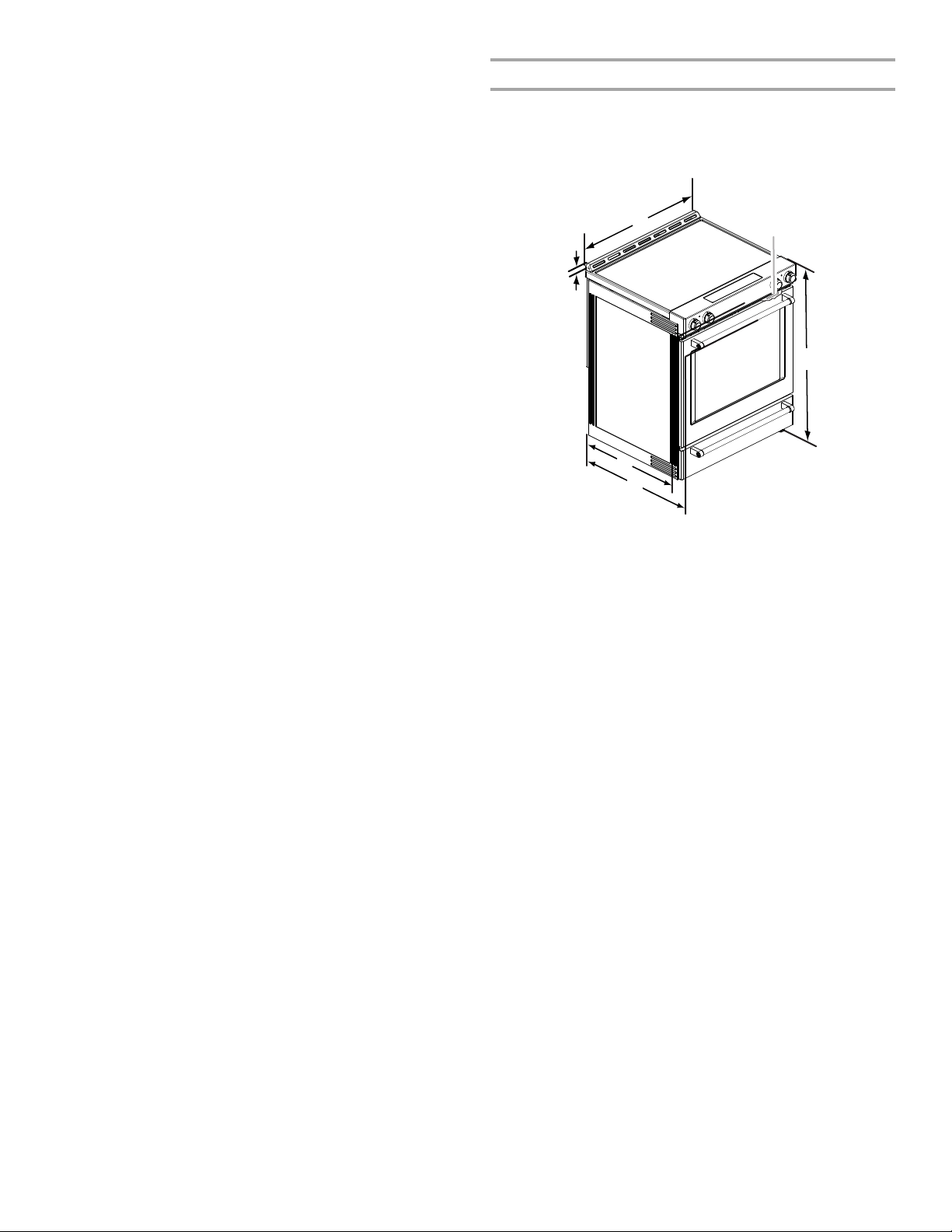
Product Dimensions
This manual covers several models. Your model may appear
different from the models depicted. Dimensions given are
maximum dimensions across all models.
Model KSEB900
A. 1
³⁄₁₆
" (3.0 cm) height from cooktop
to top of vent
B. 29
⁷⁄₈
" (75.9 cm)
C. Model/serial/rating plate (located
behind the oven door on the top
right-hand side of the oven frame)
D. 36" (91.4 cm) height to top of
cooktop edge with leveling legs
screwed in all the way*
E. 28
⁵⁄₁₆
" (71.9 cm) max. depth
from front of console to
back of range
F. 2 8
⁷⁄₈
" (73.3 cm) max. depth
from handle to back of
range
IMPORTANT: Range must be level after installation. Follow the
instructions in the “Level Range” section. Using the cooktop as a
reference for leveling the range is not recommended.
*Range can be raised approximately 1" (2.5 cm) by adjusting
the leveling legs.
4
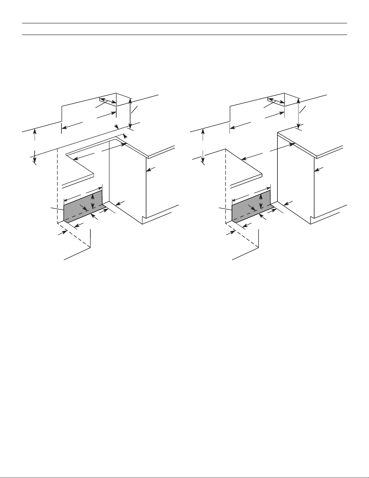
Cabinet Dimensions
K
A
B
C
D
E
G
H
I
J
F
I
L
K
A
B
C
D
E
G
H
I
J
F
I
Cabinet opening dimensions shown are for 25" (64.0 cm) countertop depth, 24" (61.0 cm) base cabinet depth and 36" (91.4 cm)
countertop height.
IMPORTANT: If installing a range hood or microwave hood combination above the range, follow the range hood or microwave hood
combination installation instructions for dimensional clearances above the cooktop surface.
Range may be installed next to combustible walls with zero clearance.
NOTE: When installed in a slide-in cutout, the front of oven door may protrude beyond the base cabinet.
Slide-In Cutout Freestanding Cutout
A. 18" (45.7 cm) upper side cabinet to countertop
B. 13" (33 cm) max. upper cabinet depth
C. 30" (76.2 cm) min. opening width
D. For minimum clearance to top of cooktop, see NOTE*.
E. 30" (76.2 cm) min. opening width
F. The shaded area is recommended for installation of grounded
outlet.
G. 13
¹⁄₈
" (33.3 cm)
H. 7
¹¹⁄₁₆
" (19.5 cm)
I. 4
¹³⁄₁₆
" (12.2 cm)
J. 3
¹¹⁄₁₆
" (9.4 cm) plus measurement of L
K. Cabinet door or hinges should not extend into the cutout.
L. Remaining counter depth should not exceed 2¼" (5.7 cm).
A. 18" (45.7 cm) upper side cabinet to countertop
B. 13" (33 cm) max. upper cabinet depth
C. 30" (76.2 cm) min. opening width
D. For minimum clearance to top of cooktop, see NOTE*.
E. 30" (76.2 cm) min. opening width
F. The shaded area is recommended for installation of grounded
outlet.
G. 13
¹⁄₈
" (33.3 cm)
H. 7
¹¹⁄₁₆
" (19.5 cm)
I. 4
¹³⁄₁₆
" (12.2 cm)
J. 3
¹¹⁄₁₆
" (9.4 cm)
K. Cabinet door or hinges should not extend into the cutout.
*NOTE: 24" (61.0 cm) minimum when bottom of wood or metal cabinet is shielded by not less than ¹⁄₄" (0.64 cm) flame retardant
millboard covered with not less than No. 28 MSG sheet steel, 0.015" (0.4 mm) stainless steel, 0.024" (0.6 mm) aluminum or 0.020"
(0.5 mm) copper.
30" (76.2 cm) minimum clearance between the top of the cooking platform and the bottom of an uncovered wood or metal cabinet.
5
 Loading...