

KitchenAid KSGG700EBS Wiring Diagram
PELIGRO
Peligro de Choque Eléctrico
Las mediciones de voltaje para diagnóstico deberán
ser realizadas solamente por técnicos autorizados.
Después de realizar mediciones de voltaje, desconecte
el suministro de energía antes del servicio.
No seguir estas instrucciones puede ocasionar la
muerte o choque eléctrico.
ADVERTENCIA
Peligro de Choque Eléctrico
Desconecte el suministro de energía antes de darle
mantenimiento.
Vuelva a colocar todos los componentes y paneles
antes de hacerlo funcionar.
No seguir estas instrucciones puede ocasionar la
muerte o choque eléctrico.
W11326872A
DANGER
Electrical Shock Hazard
Only authorized technicians should perform
diagnostic voltage measurements.
After performing voltage measurements,
disconnect power before servicing.
Failure to follow these instructions can result in
death or electrical shock.
WARNING
Electrical Shock Hazard
Disconnect power before servicing.
Replace all parts and panels before operating.
Failure to do so can result in death or
electrical shock.
Voltage Measurement Safety Information
When performing live voltage measurements, you
must do the following:
■ Verify the controls are in the off position so that the
appliance does not start when energized.
■ Allow enough space to perform the voltage measurements
without obstructions.
■ Keep other people a safe distance away from the appliance
to prevent potential injury.
■ Always use the proper testing equipment.
■ After voltage measurements, always disconnect power
before servicing.
ACTIVATING THE SERVICE DIAGNOSTIC MODES
1. Enter Diagnostics Mode by pressing CANCEL>CANCEL>START
within 5 seconds.
NOTE: After each test, press CANCEL to return to the clock. Re-enter
the diagnostic mode by pressing CANCEL>CANCEL>START within
5 seconds.
2. Press the number 3 or 6 keypads to read the following:
■ Usage
■ Relay Usage
■ Engineering mode
■ Test mode
■ Faults
NOTES:
■ The Cancel keypad can be pressed at any time when the control
is in the Diagnostic Mode or any of the sub-menus. Pressing
the Cancel keypad twice will return the control to the time of day
screen.
■ Entering Diagnostic Mode will cancel any active oven operation.
■ Enter the Diagnostic Mode only after the oven is cool.
■ Automatic test is a self-diagnostic function built into the oven
control.
■ Diagnostic Mode automatically times out and returns to the time
of day screen after 5 minutes.
■ To erase all error codes: Enter Diagnostic Mode by pressing
CANCEL>CANCEL>START within 5 seconds. Press the number
3 or 6 keypads until “Faults” appears. Press START TIME or
DELAY START to clear all error codes.
■ Version
■ Display
■ Control Reset
■ Auto Test
FOR SERVICE TECHNICIAN’S USE ONLY / POUR LE TECHNICIEN SEULEMENT
DANGER
Risque de choc électrique
Seul un technicien autorisé est habilité à eff ectuer des
mesures de tension aux fi ns de diagnostic.
Après avoir eff ectué des mesures de tension,
déconnecter la source de courant électrique avant
toute intervention.
Le non-respect de ces instructions peut causer un
décès ou un choc électrique.
AVERTISSEMENT
Risque de choc électrique
Déconnecter la source de courant électrique avant
l’entretien.
Replacer pièces et panneaux avant de faire la remise
en marche.
Le non-respect de ces instructions peut causer un
décès ou un choc électrique.
Informations de sécurité concernant la mesure de la tension
La mesure de la tension doit être effectuée de la manière suivante:
■ Vérier que les commandes sont à la position OFF (Arrêt)
pour que l’appareil ne démarre pas lorsqu’il est mis sous
tension.
■ Laisser sufsamment d’espace pour pouvoir faire les mesures
de tension sans qu’il y ait d’obstacle.
■ Éloigner toutes les autres personnes présentes sufsamment
loin de l’appareil pour éviter les risques de blessure.
■ Toujours utiliser l’équipement de test approprié.
■ Après les mesures de tension, toujours déconnecter la source
de courant électrique avant de procéder au service.
ACTIVATION DES MODES DE TEST DE
DIAGNOSTIC DE SERVICE
1. Accéder au mode de diagnostic en appuyant sur
CANCEL>CANCEL>START (annuler>annuler>mise en marche)
en moins de 5 secondes.
REMARQUE : Après chaque test, appuyer sur CANCEL (annuler)
pour revenir à l’horloge. Accéder au mode de diagnostic de nouveau
en appuyant sur CANCEL>CANCEL>START (annuler>annuler>mise
en marche) en moins de 5 secondes.
2. Appuyer sur les touches numéro 3 ou 6 pour consulter les
informations suivantes :
■ Usage (utilisation)
■ Relay Usage (emploi relais)
■ Engineering mode (mode
ingénierie)
■ Test mode (mode de test)
■ Faults (anomalies)
REMARQUES :
■ La touche Cancel (annuler) peut être utilisée à tout moment
en mode de diagnostic ou dans l’un des sous-menus. Appuyer
deux fois sur la touche Cancel (annuler) pour que le module de
commande revienne à l’écran indiquant l’heure du jour.
■ Version
■ Display (afchage)
■ Control Reset (réinitialisation
du module de commande)
■ Auto Test (test automatique)
■ Le fait d’accéder au mode de diagnostic annule tout fonctionnement actif du four.
■ Attendre que le four ait refroidi avant d’entrer dans le mode de diagnostic.
■ Le test automatique est une fonction d’autodiagnostic intégré au module de commande
du four.
■ Le mode de diagnostic s’interrompt automatiquement après 5 minutes pour revenir à
■ Pour effacer tous les codes d’erreur : accéder au mode de diagnostic en appuyant sur
CANCEL>CANCEL>START (annuler>annuler>mise en marche) en moins de
5 secondes. Appuyer sur les touches numéro 3 ou 6 jusqu’à afcher “Faults”
(anomalies) : appuyer sur START TIME (heure de mise en marche) ou DELAY START
(mise en marche différée) pour effacer tous les codes d’erreur.
l’écran indiquant l’heure du jour.
ERROR CODES (OVEN) / CODES D’ERREUR (FOUR)
Code/Code Description/Description
F1E0 EEPROM Communication Error
F2E0 Keypad Disconnected
F2E1 Stuck Keypad
F3E0 Main Oven Sensor Open or Shorted
F3E2 Drawer Sensor Open or Shorted
F6E1 Over Temp
F8E0 Cooling Fan Speed Too Low
F8E2 Cooling Fan Speed Too High
F9E0 Miswired
EEPROM – erreur communication
Clavier déconnecté
Touche bloquée
Capteur du four principal ouvert ou court-circuité
Capteur du tiroir-réchaud ouvert ou court-circuité
Température excessive
Rotation du ventilateur de refroidissement trop lente
Rotation du ventilateur de refroidissement trop rapide
Câblage incorrect
ERROR CODES (INDUCTION COOKTOP) / CODES
D’ERREUR (TABLE DE CUISSON À INDUCTION)
Code/Code Description/Description
F-12 Coil under current / Élément à spirale soumis à un courant
F-21 Supply power frequency / Fréquence de l’alimentation électrique
F-25 Stuck fan on Induction Power System (IPS) (Right or left side fan,
F-36, F-37 Temperature sensor is not working
F-40 Induction Power System (IPS) failure
F-42 Power supply / Alimentation électrique
F-43 Under voltage / Sous-tension
F-47 Power supply from Induction Power Control (IPC) to User Interface is
F-56 Wrong or invalid conguration / Conguration incorrecte ou invalide
F-58 Wrong or invalid conguration (IPS)
F-60 UI does not work / Interface utilisateur non opérationnelle
C-81, C-82 Over temperature / Température maximale dépassée
C-83 Temperature sensor stuck / Capteur de température bloqué
depending on which side of the display the failure is on.)
Ventilateur bloqué sur le système d’alimentation de l’induction (IPS)
(ventilateur droit ou gauche selon le côté de l’afchage indiquant la
panne).
Capteur de température non opérationnel
Anomalie du système d’alimentation de l’induction (IPS)
missing or WIDE communication error between UI and Induction Power
Control (IPC) or an open fuse on the lter board
L’alimentation électrique de la carte de commande de la puissance
d’induction (IPC) vers l’interface utilisateur est coupée, ou une erreur de
communication large (WIDE) s’est produite entre l’interface utilisateur et
la carte de commande de la puissance d’induction (IPC), ou un fusible
est grillé sur la carte de ltrage
Conguration incorrecte ou invalide (IPS)
RESISTANCES (OVEN) /
Component / Composants
Door switch
Contacteur de la porte
Main cavity oven temp sensor
Capteur température four principal
Drawer oven temp sensor
Capteur température tiroir-réchaud
Oven light
Lampe du four
Thermofuse (TOD)
Fusible thermique
Bake igniter (gas)
Allumeur de cuisson au four (gaz)
Broil igniter (gas)
Allumeur de cuisson au gril (gaz)
Main cavity bake element
Élément de cuisson au four
principal
Broil element
Élément de cuisson au gril
Drawer element
Élément du tiroir-réchaud
Convection fan motor
Moteur du ventilateur de
convection
Cooktop element (single)
Élément simple de la table de
cuisson
Single, dual, and triple burner
elements
Éléments de brûleur simple,
double et triple
RÉSISTANCE
Pinout /
Brochage
P7-4 to P7-5
P7-4 à P7-5
P10-4 to P10-3
P10-4 à P10-3
P10-1 to P10-2
P10-1 à P10-2
P5-4 to WH
(Neutral) P6-3
P5-4 à W
(neutre) P6-3
P4-2 to P6-1
P4-2 à P6-1
P2-3 to WH
(Neutral) P6-3
P2-3 à BL
(neutre) P6-3
P4-2 to WH
(Neutral) P6-3
P4-2 à BL
(neutre) P6-3
P2-3 to P15-1
P2-3 à P15-1
P4-2 to P15-1
P4-2 à P15-1
P3-1 to WH
(Neutral) P6-3
P3-1 à BL
(neutre) P6-3
P5-3 to WH
(Neutral) P6-3
P5-3 à BL
(neutre) P6-3
H1 to H2
H1 à H2
Term H1(Single
only)
Term 4, 4A
(double only)
to Term 4, 4A
Borne
H1(simple
uniquement)
ou borne 4,
4A (double
uniquement) à
Borne 4, 4A
Term 1, 4, 4A
(triple only) to
Term 2 A
Borne 1, 4,
4A (triple
seulement) à
Borne 2A
(FOUR)
Resistance or Voltage /
Résistance ou tension
5 VDC
5 V CC
1000-1200 Ω at room
temperature
1000 - 1200 Ω à
température ambiante
1000-1200 Ω at room
temperature
1000 - 1200 Ω à
température ambiante
0-40 Ω nominal
240 VAC
240 VCA
40-400 Ω at room
temperature
40 - 400 Ω à température
ambiante
40-400 Ω at room
temperature
40 - 400 Ω à température
ambiante
10-40 Ω nominal
10-40 Ω nominal
10-40 Ω nominal
80-95 Ω
23-83 Ω nominal
120 VAC
120 VCA
240 VAC
240 VCA
RESISTANCES
RÉSISTANCE
Component / Composants
EMI lter board
Carte de ltrage EMI
Induction Power Control (IPC):
Left and right
Carte de commande de la
puissance d’induction (IPC) :
Gauche et droite
Induction Power Control (IPC)
to blower fan: Left and right
Carte de commande de la
puissance d’induction (IPC) au
ventilateur : Gauche et droite
Induction Power Control (IPC)
to the element sensor:
Left and right
Carte de commande de la
puissance d’induction (IPC) au
capteur de l’élément : Gauche
et droite
Induction Power Control (IPC)
to the User Interface
Carte de commande de la
puissance d’induction (IPC) à
l’interface utilisateur
(TABLE DE CUISSON À INDUCTION)
(INDUCTION COOKTOP)
Pinout /
Brochage
J1 - BR - BU
J1 - MAR - BU
J1 - BR - BU
J1 - MAR - BU
J205 - (BK) - (R)
J205 - (BK) - (BU)
J205 - (N) - (R)
J205 - (N) - (BU)
J604 - (1) - (2)
J605 - (1) - (2)
J806 - BK - 1
J806 - N - 1
J806 - LT BU - 2
J806 - BU CL - 2
J806 - W - 3
J806 - BL - 3
J806 - R - 4 Standby
J806 - Y - 5
J806 - JA - 5
Resistance or Voltage /
Résistance ou tension
From 208 VAC to
240 VAC - 60 Hz
De 208 VCA à
240 VCA - 60 Hz
From 208 VAC to
240 VAC - 60 Hz
De 208 VCA à
240 VCA - 60 Hz
From 0 VDC to 12 VDC
De 0 V CC à 12 V CC
+5 VDC
+10.5 V
+5 V CC
+10,5 V
+5 VDC
+5 V CC
WIDE_DATA
Ground
Terre
Veille
+10 VDC
+10 V CC
© 2019
/
0 V
0 V
W11326872A
FOR SERVICE TECHNICIAN’S USE ONLY / POUR LE TECHNICIEN SEULEMENT
IMPORTANT: Electrostatic discharge may cause damage to machine control electronics. Refer to online Tech Sheet for additional information.
Check for proper voltage by completing the following steps:
1. Disconnect the power or unplug the appliance.
2. Connect voltage measurement equipment to proper connectors.
3. Plug in appliance or reconnect power and conrm voltage reading.
4. Disconnect the power or unplug the appliance.
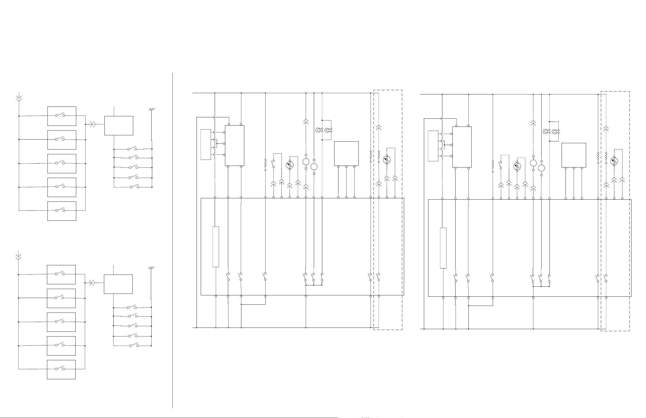
WIRE DIAGRAM / SCHÉMA DE CÂBLAGE
© 2019
IMPORTANT: Une décharge d’électricité statique peut faire subir des dommages aux circuits électroniques. Pour plus d’informations, se reporter à la che technique
du produit en ligne.
Contrôler que la tension est correcte en effectuant les étapes suivantes :
1. Déconnecter la source de courant électrique ou débrancher l’appareil.
2. Brancher le voltmètre au connecteur approprié.
3. Brancher l’appareil ou reconnecter la source de courant électrique et vérier la tension.
4. Déconnecter la source de courant électrique ou débrancher l’appareil.
L1
Igniter Switches
BK
BK
BK
BK
BK
COOKTOP
TN
LR
TN
LF
TN
RR
TN
RF
TN
C
BK
N
Spark
Module
Cooktop
Igniters
GND
N
Solenoid Valve
BU to OR 216 ohms
RD to OR 216 ohms
P6-3
WH
WH
BU
OR
RD
J1-3
J1-2
J1-1
P2-3
BK
J1-10
DSI Board
J1-6
RD/WH
J1-4
J1-7
P4-2
WH
J1-1 to J1-2: 8-18 VAC
J1-10 to J1-4: 120 VAC
BU/WH
J1-3 to J1-2: 8-18 VAC
J1-7 to J1-4: 120 VAC
J1-6 to J1-4: 120 VAC
WH
Door Position Switch
Convection 914W
YL
P1-4
P7-5
YL
OVEN
GY
P7-4
Main Oven Temp Sensor
VT
P10-4
P10-3
FOUR
WH
YL
P7-1
WH
Drawer Temp Sensor
Broil Assist 1200 W
Bake Drawer 1200 W
BU
OR/WH
P1-1
P3-1
P10-1
GY
GY
P10-2
On some models
WH
Convect Fan
M
OR
P5-3
WH
Oven Light 40 W
BK/WH
P5-4
Oven Light 40 W
Hall
Effect
Signal
5 VDC
BK
RD
P7-7
P7-3
Sensor
GND
WH
M
Cooling Fan
VT
VT
P5-1
N
Électrovanne
R à OR 216 ohms
BU à OR 216 ohms
P6-3
J1-6 à J1-4 : 120 VCA
Convection 914 W
P1-4
BL
Contacteur de la porte
JA
JA
GR
P7-4
P7-5
BL
Capteur thermométrique
du four principal
VI
P10-4
P10-3
Ventilateur de convection
M
Ventilateur de refroidissement
VI
VI
P5-3
P5-1
BL
BL
Lampe du four 40 W
M
N/BL
OR
P5-4
Lampe du four 40 W
Capteur
à effet Hall
Terre
Signal
5 VCC
JA
N
R
P7-7
P7-1
P7-3
BL
BL
N
J1-4
J1-10
J1-3
BU
J1-1 à J1-2 : 8-18 VCA
Carte DSI
J1-7
BU/BL
P4-2
J1-3 à J1-2 : 8-18 VCA
J1-7 à J1-4 : 120 VCA
J1-10 à J1-4 : 120 VCA
J1-2
OR
J1-1
R
J1-6
BL
R/BL
P2-3
BL
BL
Capteur thermométrique du tiroir
P10-1
GR
P10-2
Sur certains modèles
GR
Élément auxiliaire pour cuisson au gril 1 200 W
Tiroir de cuisson au four 1 200 W
BU
OR/BL
P1-1
P3-1
L1
TABLE DE CUISSON
Contacteurs de l'allumeur
N
N
N
N
N
ArG
AvG
ArD
AvD
Power Supply
BRO
BRO
BRO
BRO
N
Module
générateur
N
d’étincelles
Terre
L1
Oven Control Maxwell
Bake (K4)
P2-1
P6-1
BK
BK
Broil (K5)
P4-1
BK
Convect (K2)
P1-3
BK
Cooling Fan (K9)
P5-9
BK
Convect Fan (K7)
Oven Light (K6)
Broil Assist (K3)
Bake Drawer (K1)
P2-4
P3-2
BK
BK
L1
Allumeurs de la table
Commande du four Maxwell
Alimentation électrique
Cuisson au four (K4)
Cuisson au gril (K5)
P2-1
P6-1
N
P4-1
N
Convection (K2)
P1-3
N
N
Ventilateur de refroidissement (K9)
Ventilateur de convection (K7)
Lampe du four (K6)
P5-9
N
Élément auxiliaire pour cuisson au gril (K3)
Tiroir de cuisson au four (K1)
P2-4
P3-2
N
N
de cuisson
BRO
C
 Loading...