

KitchenAid KPED892K Installation Instructions
Model KPED892K Exterior Blower
Installation Instructions and Use and Care Guide
Your safety and the safety of
others are very important.
We have provided many important safety
messages in this manual and on your
appliance. Always read and obey all safety
messages.
This is the safety alert symbol.
This symbol alerts you to
potential hazards that can kill
or hurt you and others.
All safety messages will follow the safety
alert symbol and either the word
“DANGER” or “WARNING”. These
words mean:
All safety messages will tell you what the
potential hazard is, tell you how to reduce
the chance of injury, and tell you what can
happen if the instructions are not followed.
You can be killed or seriously injured if
you don’t immediately
follow instructions.
You can be killed or seriously injured if
you don’t follow instructions.
WARNING
Before you start...
Electrical requirements
DANGER
IMPORTANT: READ AND SAVE THESE INSTRUCTIONS.
The installer must leave these instructions with the homeowner.The homeowner must keep these instructions for future
reference and for local electrical inspectors use.
Proper installation is your responsibility.
Make sure you have everything
necessary for correct installation. It is
the responsibility of the installer to
comply with the clearances specified.
To avoid damage to motor bearings
and impellers, keep drywall spray,
construction dust, etc. away from the
exterior blower.
Important: Observe all governing
codes and ordinances.
Important: Observe all governing
codes and ordinances.
It is the customer’s responsibility:
•To contact a qualified electrical
installer.
•To assure that the electrical installation
is adequate and in conformance with
National Electrical Code, ANSI/NFPA
70 — latest edition*, or CSA
Standards C22.1-94, Canadian
Electrical Code, Part 1 and C22.2
No.0-M91 - latest edition** and all local
codes and ordinances.
If codes permit and a separate ground
wire is used, it is recommended that a
qualified electrician determine that the
ground path is adequate.
Do not ground to a gas pipe.
Check with a qualified electrician if
you are not sure exterior blower is
properly grounded.
Do not have a fuse in the neutral or
ground circuit.
IMPORTANT
Before installing exterior mounted
blower, read the installation instructions
for the Kitchen downdraft system of
range hood that will be used in
conjunction with this power system.
The exterior blower is factory set at
900 cfm (424.7 l/s).
This fan is suitable for use with solidstate speed controls.
A. A 120-volt, 60-Hz, AC-only supply
wired for 15 amp service is required.
B.The blower motor must be
connected with copper wire only.
Copies of standards listed may be
obtained from:
* National Fire Protection Association
One Batterymarch Park
Quincy, Massachusetts 02269
** CSA International
8501 East Pleasant Valley Road
Cleveland, Ohio 44131-5575
Page 1
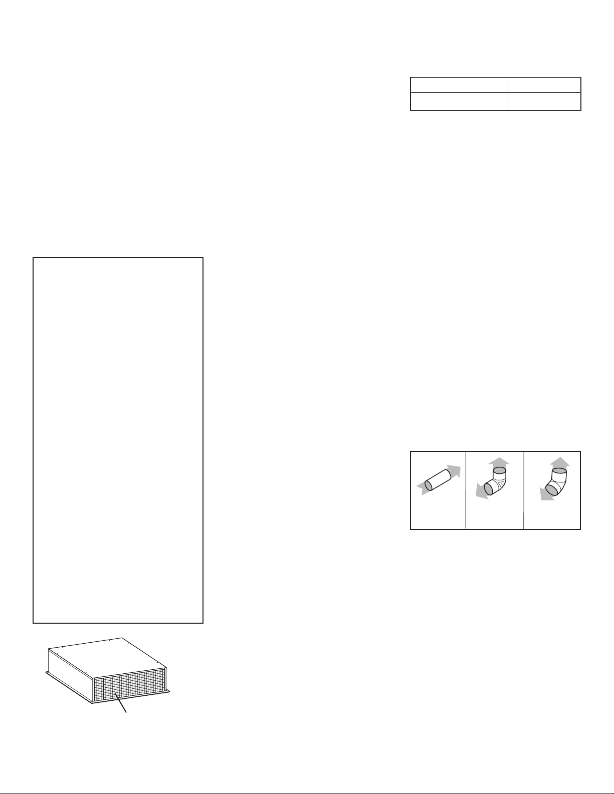
Care of your
exterior blower
Disconnect power supply and lock out
service panel before cleaning or
servicing.
To clean, remove cover and vacuum
blower and housing, being careful not
to damage blower wheel.
The motor is permanently lubricated.
Do not oil or disassemble.
Venting requirements
Maximum length of
vent system
Determine the length of
vent system you need
WARNING — TO REDUCE THE
RISK OF FIRE, ELECTRIC SHOCK,
OR INJURY TO PERSONS,
OBSERVE THE FOLLOWING:
Installation work and electrical
wiring must be done by qualified
person(s) in accordance with all
applicable Codes and Standards,
including Fire Rated Construction.
Sufficient air is needed for proper
combustion and exhausting of
gases through the flue (chimney)
of fuel burning equipment to
prevent back drafting. Follow the
heating equipment
manufacturer’s guideline and
safety standards such as those
published by the National Fire
Protection Association (NFPA),
and the American Society of
Heating Refrigeration and Air
Conditioning Engineers
(ASHRAE), and the local code
authorities.
When cutting or drilling into wall
or ceiling, do not damage
electrical wiring and other hidden
utilities.
Ducted fans must always be
vented to the outdoors.
WARNING — To reduce the risk of
fire, use only metal ductwork.
This unit must be grounded.
C.The blower motor must be
connected to the downdraft vent
system wiring as described in the
downdraft vent system instructions for
connecting the exterior blower motor
wiring. Flexible armored or nonmetallic
cable must be used. A U.L./CSA-listed
strain relief must be provided at each
end of the power supply cable.
Wire sizes must conform to the
requirements of the National Electrical
Code ANSI/NFPA 70 — latest edition*
or Canadian Electrical Code, C22.1
and C22.2 No.113-M1984 (or latest
edition),** and all local codes and
ordinances. 14 gauge wire (minimum)
is recommended.
Copies of standards listed may be
obtained from:
* National Fire Protection Association
One Batterymarch Park
Quincy, Massachusetts 02269
** CSA International
8501 East Pleasant Valley Road
Cleveland, Ohio 44131-5575
90° elbow =
5 ft. (1.5 m)
1 ft. round =
1 ft. (0.3 m)
45° elbow =
2.5 ft. (0.8 m)
Recommended standard
10" (25.4 cm) fittings
Determine which venting method is best
for your application.Vent system can
extend either through the wall or the
roof.
Locate the exterior blower so that the
length of the vent system and the
number of elbows is kept to a minimum
to provide efficient performance. Where
possible, exterior blower should be
centered between wall studs or roof
rafters.The size of the vent system
should be uniform. Do not install two
elbows together.Use duct tape to seal
all joints in the vent system. Use
caulking to seal exterior wall or floor
opening around the cap.
Flexible vent is not recommended. It
creates back pressure/air turbulence
and greatly reduces performance.
Make sure there is proper clearance
within the wall or floor for exhaust vent
before making cutouts. Avoid pipes,
wires, or other vent systems that may
be running through the wall. Do not cut
a joist or stud unless absolutely
necessary. If a joist or stud must be cut,
then a supporting frame must be
constructed.
The exterior blower carton contains a
black plastic vent collar and a vent collar
plate.
• The black plastic vent collar attaches
to the exterior blower using four
screws provided.The 10" (25.4 cm)
round vent system attaches to this
collar.
• The vent collar plate attaches to the
front of the downdraft vent system
plenum so that the 10" (25.4 cm)
round vent can be attached to the
downdraft vent system.
Make sure that there is enough space
for any vent transitions that may be
needed between the exterior blower and
the connecting vent system.
For optimum performance, locate any
necessary vent transitions nearest to
the rangehood or downdraft that will be
used with this power system.
This exterior blower requires a separate
U.L./CSA approved wiring cable that
should be installed at the same time the
vent system is being installed.
Vent Length
10" (25.4 cm) round 55 ft. (16.8 m)
Vent length is given as a general
reference only. For a longer vent run, or
smaller vent system, contact a qualified
and trained vent installer. Check with local
codes for makeup air requirements, if any.
It is recommended that you use round
vent instead of rectangular vent,
especially if elbows are required. If
rectangular vent is required, if should be
transitioned to 10" (25.4 cm) round vent
as soon as possible.
For best performance, use no more
than three 90° elbows.If more than one
elbow is used, make sure that there is
a minimum of 24 inches (61 cm) of
straight vent between any two elbows.
Do not install two elbows together.
To calculate the length of system you
need, add the equivalent feet (meters)
from chart below for each vent piece
that will be needed.
Page 2
install this side of the fan facing
an unoccupied space.
Now start...
Excessive Weight Hazard
Use two or more people to move
and install external blower.
Failure to do so can result in
back or other injury.
WARNING
1.
Discard any cardboard packaging
from the blower wheel.
2.
Remove wiring box cover and
screws.
3.
Attach an appropriate U.L./CSAlisted strain relief in the hole at the rear
of the wiring box.
Follow the instructions for your type of
installation.
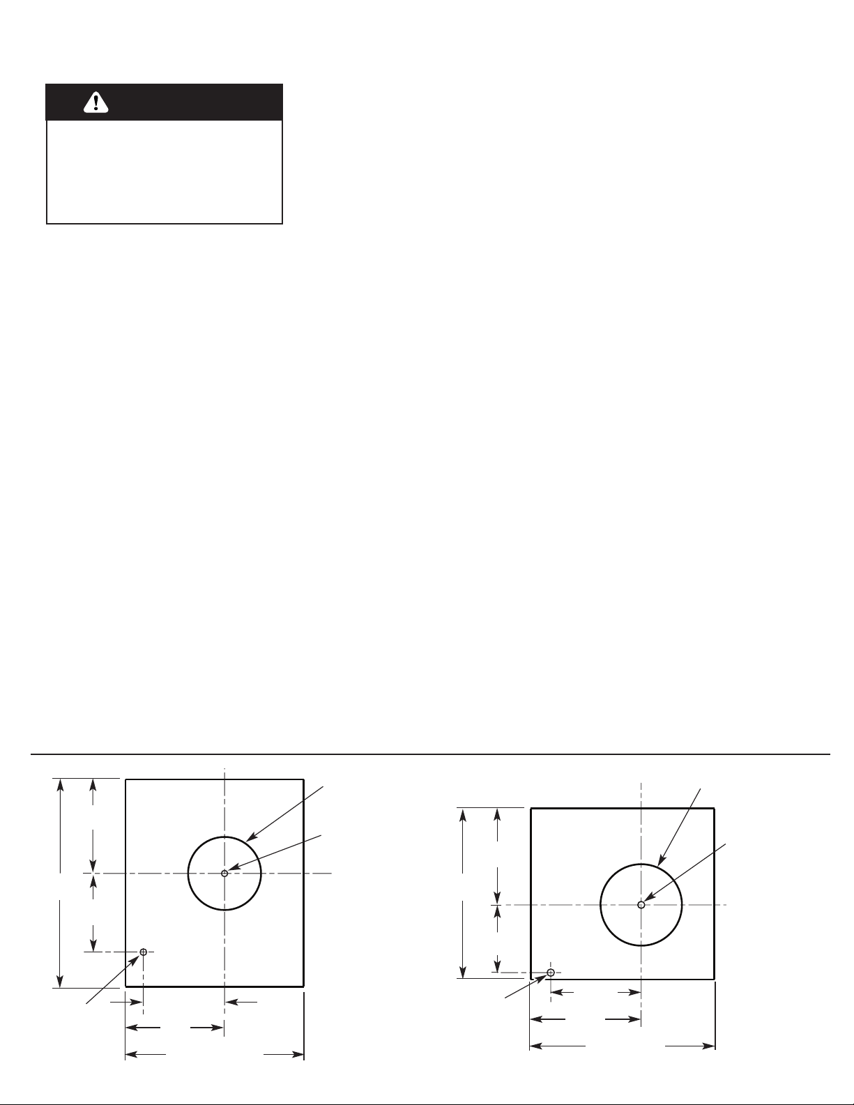
WALL INSTALLATIONS
ROOF INSTALLATIONS
1.Choose a location on an outside
wall where no wall studs, wires, pipes,
etc. run through the opening area. A
minimum distance of 24" (61 cm) from
exterior blower to ground may be
required depending on local code.
Make sure to leave room for anticipated
snowfall in your region.
2.Drill the guide hole in the center
of the 11" (27.9 cm) diameter opening
area.
3.Mark a 27-1/2" x 34" (69.9 x
86.4 cm) rectangle on wall as indicated
in FIGURE 1.
4.
Cut a rectangular hole in the
siding only. Do not cut sheathing. Nail
down all siding ends.
5.
Mark an 11" (27.9 cm) diameter
circle around Guide Hole as indicated
in FIGURE 1. Mark center of the
1-1/4" (or 3.0 cm) diameter hole for
electrical wiring as indicated in
FIGURE 1.
6.
Cut 11" (27.9 cm) diameter hole
in sheathing. Drill the 1-1/4" (or 3.0
cm) diameter electrical wiring hole.
7.
Run a large bead of caulk on the
back side of the housing along the outer
edge.
8.
Center the exterior blower ring in
the 11"
(27.9 cm) diameter hole, making
sure that the 1-1/4" (or 3.0 cm) diameter
electrical wiring hole lines up with the
hole in the wiring box.
9.
Attach the exterior blower to wall
using screws appropriate for your
installation. All four holes in the back
panel must be filled to prevent moisture
that may get inside the
exterior
blower
housing from leaking into the home.
10.
Seal all around the mounting
screw heads with caulk.
FIGURE 1 FIGURE 2
34"
(86.4 cm)
15"
(38.1 cm)
10-5/8"
(27 cm)
1-1/4"
(3.0 cm)
dia. hole
9-3/8"
(23.8 cm)
14"
(35.6 cm)
9-3/8"
(23.8 cm)
23"
(58.4 cm)
12-3/4"
(32.4 cm)
10-5/8"
(27 cm)
1-1/4"
(3.0 cm)
dia. hole
11" (27.9 cm)
dia. hole
guide
hole
guide
hole
11" (27.9 cm)
dia. hole
27-1/2" (69.9 cm)
13-3/4"
(34.9 cm)
25" (63.5 cm)
1.
Choose location on rear slope of
roof that minimizes vent run. Avoid
obstacles such as TV leads, electric
lines, etc. If
exterior
blower top is level
with roof peak, it will not be seen from
street. Remember this location as you
work from inside the attic.
2.
Mark a point half-way between
the rafters and drill a guide hole at this
point.
3.
From the outside, using the guide
hole as a starting point, mark the
rectangular cut-out as indicated in
FIGURE 2. Remove ONLY the shingles
inTHIS AREA.
4.
Mark an 11" (27.9 cm) diameter
circle around guide hole as indicated in
FIGURE 2. Mark center of the 1-1/4"
(or 3.0 cm) diameter hole for the
electrical wiring as indicated in
FIGURE 2.
5.
Cut out the roof boards along the
11" (27.9 cm) diameter circle. Drill the
1-1/4" (or 3.0 cm) diameter electrical
wiring hole.
Page 3
11.
Go to "Making electrical and
vent connections", Page 4.
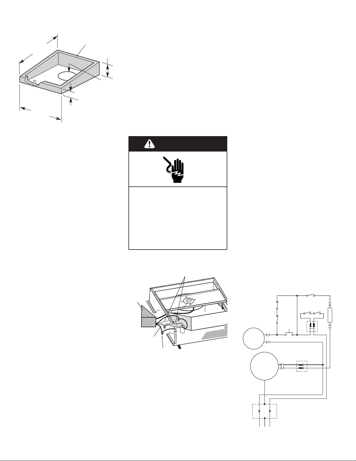
Making electrical and vent connections
If you are installing external
blower on a flat roof:
FIGURE 3
Locate the 11" (27.9 cm) dia. hole
between rafters.
Build a sloping base that will mount the
exterior blower at a minimum pitch of
2-1/2" (6.4 cm).Weatherproof the base
as required.
Locate the base so that the exterior
blower's vent aligns with the 11"
(27.9 cm) dia. hole and the blower sits
evenly on the base with no gaps. Note:
Make sure that the discharge end of the
exterior blower faces away from the
direction of prevailing winds.
Use dimensions from either FIGURE 1
or 2 (Page 3) to locate the 1-1/4"
(3.0 cm) dia. wiring hole.
33-1/2"
(85.1 cm)
2 x 4 framing
recommended
2"
(5.1 cm)
7"
(17.8 cm)
27"
(68.6 cm)
11" (27.9 cm)
dia. hole
discharge side
of blower
6.
Remove roofing nails from the
upper two-thirds of the shingles to allow
the back flashing sheet on the exterior
blower housing to fit under them.
7.
Center the exterior blower ring in
the 11" (27.9 cm) diameter hole, making
sure that the 1-1/4" (or 3.0 cm) diameter
electrical wiring hole lines up with the
hole in the wiring box.
8.
Attach the exterior blower to roof
or frame using screws appropriate for
your installation.All four holes in the
back panel must be filled to prevent
moisture that may get inside the remote
blower housing from leaking into the
home.
9.
Seal all the shingles around the
exterior blower housing, flashing sheet,
and mounting screw heads or frame with
Electrical Shock Hazard
Disconnect power before
making electrical connections.
Connect the ground wire to
green ground screw in wiring
box.
Failure to do so can result in
death or electrical shock.
WARNING
1.
Remove the cover from the exterior
blower.Then remove the wiring box cover.
2.
Pull electrical wiring through the
hole in the blower base and secure it
according to local codes.
3.
Attach the black plastic vent collar
to the exterior blower with the four screws
provided. Connect the vent system to this
collar and seal the connection securely
with duct tape.
4.
Make the electrical connections.
(See FIGURE 3 and wiring diagram.)
Connect the white and black wires of the
power supply cable wire to the white and
black wires in the wiring box with twist-on
connector.
Connect the green power supply ground
wire to the green ground screw.
5.
Replace the wiring box cover and
screws taking care not to pinch the wiring
under the wiring box cover.
6.
Turn on power (See Use and Care
Guide that came with your vent hood
system). Check operation of blower and
make sure damper is opening freely.
7.
Reinstall exterior blower housing.
120 VA C
line in
green ground
wires
white
wires
wiring
box
cover
black
wires
WIRING
DIAGRAM
roofing cement.
Top and side flanges of the back plate
may be covered with trim. It is
recommended that electrical connection
be made and checked first.Do not block
the vent grill opening at the bottom of
the trim. Doing so will decrease blower
performance.
Page 4
BLK
UP N.C.
SWITCH
.
BLK
PUSH
SWITCH
BUTTON
DOWN N.C
N.O.
M
~
REMOTE
BLOWER
GRN
WHT
GRN
BLU
WHT
BLK
WHT
BLK
WHT
BLK
WIRING
BOX
LINE IN
120 VAC
60 Hz
GEAR
MOTOR
SWITCH
FAN N.O.
SWITCH
FILTER N.O.
BLK BLK
WHT
BLK
WHT
BLK
BLK
BLK
OL
SPEED CONTR
 Loading...