

KitchenAid KHWS01PMT / WH, KHWS01PWH Technical Education

TECHNICAL EDUCATION
FRONT-LOADING
AUTOMATIC WASHER
KAL-4
MODEL KHWS01PMT / WH
JOB AID 4317352

FORWARD
This KitchenAid Job Aid “Ensemble Front-Loading Automatic Washer” (Part No. 4317352),
provides the technician with information on the installation, operation, and service of the Ensemble
Front-Loading Automatic Washer. It is to be used as a training Job Aid and Service Manual. For
specific information on the model being serviced, refer to the “Use and Care Guide,” or “Tech
Sheet” provided with the washer.
The Wiring Diagram used in this Job Aid is typical and should be used for training purposes only.
Always use the Wiring Diagram supplied with the product when servicing the unit.
GOALS AND OBJECTIVES
The goal of this Job Aid is to provide detailed information that will enable the service technician to
properly diagnose malfunctions and repair the KitchenAid Ensemble Front-Loading Automatic
Washer.
The objectives of this Job Aid are to:
• Understand and follow proper safety precautions.
• Successfully troubleshoot and diagnose malfunctions.
• Successfully perform necessary repairs.
• Successfully return the washer to its proper operational status.
WHIRLPOOL CORPORATION assumes no responsibility for any repairs made
on our products by anyone other than Authorized Service Technicians.
Copyright © 2004, Whirlpool Corporation, Benton Harbor, MI 49022
- ii -

TABLE OF CONTENTS
Page
GENERAL............................................................................................................................... 1-1
KitchenAid Model & Serial Number Designations.............................................................. 1-1
Model & Serial Number Label And Tech Sheet Locations................................................. 1-2
Specifications..................................................................................................................... 1-3
Pedestal Warranty ............................................................................................................. 1-3
KitchenAid Washer Warranty............................................................................................. 1-4
INSTALLATION INFORMATION ........................................................................................... 2-1
Installation Requirements .................................................................................................. 2-1
Installation Instructions ...................................................................................................... 2-5
Installing The Washer On The Pedestal ............................................................................ 2-7
PRODUCT OPERATION ........................................................................................................ 3-1
Theory Of Operation .......................................................................................................... 3-1
Customer Interface & Cycle Selection ............................................................................... 3-7
Cycles ................................................................................................................................ 3-8
Options ............................................................................................................................ 3-10
Modifiers .......................................................................................................................... 3-11
COMPONENT ACCESS ......................................................................................................... 4-1
Component Locations ........................................................................................................ 4-1
Removing The Console And The Touchpad/LED Assembly ............................................. 4-2
Removing The Door Lock/Switch Assembly, And The Front
Panel & Bellows ............................................................................................................. 4-4
Removing The Flowmeter.................................................................................................. 4-7
Removing The Detergent Dispenser Motor & Assembly ................................................... 4-8
Removing The Inlet Valves .............................................................................................. 4-10
Removing The Central Control Unit ................................................................................. 4-11
Removing The Interference Filter .................................................................................... 4-12
Removing The Pressure Switch ...................................................................................... 4-13
Removing The Motor Controller....................................................................................... 4-14
Removing The Temperature Sensor & The Heating Element ......................................... 4-16
Removing The Heating Element Relay............................................................................ 4-17
Removing The Drain Pump Assembly ............................................................................. 4-18
Removing The Airtrap ...................................................................................................... 4-19
Removing An Interlock Switch ......................................................................................... 4-20
Removing The Drive Motor .............................................................................................. 4-22
Removing The Tub And Basket Assembly ...................................................................... 4-24
- iii -

Page
COMPONENT TESTING ........................................................................................................ 5-1
Pressure Switch ................................................................................................................. 5-1
Detergent Dispenser Motor & Switch................................................................................. 5-2
Inlet Valve Solenoids ......................................................................................................... 5-2
Door Lock/Switch Assembly .............................................................................................. 5-3
Drain Pump Motor.............................................................................................................. 5-4
Interference Filter............................................................................................................... 5-4
Heating Element & Temperature Sensor ........................................................................... 5-5
Heating Element Relay ...................................................................................................... 5-5
Drive Motor ........................................................................................................................ 5-6
Interlock Switch.................................................................................................................. 5-6
DIAGNOSTICS & TROUBLESHOOTING .............................................................................. 6-1
WIRING DIAGRAM................................................................................................................. 7-1
TECH TIPS ............................................................................................................................. 8-1
Manual Door Latch ............................................................................................................ 8-1
Door Plunger...................................................................................................................... 8-1
- iv -

MODEL & SERIAL NUMBER DESIGNATIONS
MODEL NUMBER
GENERAL
MODEL NUMBER
PRODUCT GROUP
K = KITCHENAID
PRODUCT IDENTIFICATION
H = HORIZONTAL AXIS - DOMESTIC
FEATURE CODE
W = WASHER
FEATURE CODE
S = SUPERBA
SERIES
YEAR OF INTRODUCTION
P = 2004
COLOR CODE
MT = METEORITE
WH = WHITE
ENGINEERING CHANGE (NUMERIC)
KHWS01PMT0
MODEL NUMBER (PEDESTAL)
MODEL NUMBER L A B 2 7 0 0 P MT 0
PRODUCT GROUP
L = Domestic Laundry
PRODUCT IDENTIFICATION
A = Laundry Accessory
FEATURE CODE
B = Pedestal Base
PRODUCT WIDTH
FILLER
FILLER
YEAR OF INTRODUCTION
COLOR CODE
MT = Meteorite, Q = White
ENGINEERING CHANGE
SERIAL NUMBER
SERIAL NUMBER
DIVISION RESPONSIBILITY
CS = Schorndorf, Germany
YEAR OF PRODUCTION
P = 2003
WEEK OF PRODUCTION
42 = 42ND WEEK
PRODUCT SEQUENCE NUMBER
CS P 42 09793
SERIAL NUMBER (PEDESTAL)
SERIAL NUMBER
MANUFACTURING SITE
C = CLYDE, OH
YEAR OF PRODUCTION
P = 2003
WEEK OF PRODUCTION
PRODUCT SEQUENCE NUMBER
C P 01 10001
1-1

MODEL & SERIAL NUMBER LABEL
AND TECH SHEET LOCATIONS
The Model/Serial Number label and Tech Sheet locations are shown below.
Model & Serial
Number Label
Location
Tech Sheet Location
(Behind Toe Panel)
1-2

SPECIFICATIONS
Model Number
Color
Electrical Requirements
Heating Power
Max. Current
Rated Current
Voltage
Frequency
Gallons/Normal Cycle
Capacity
Volume
Max. Spin Speed
Dimensions
Height
Height (Feet Extended)
Width
Depth
Weight
KHWS01PMT / WH
MT = Meteorite, WH = White
1,000W
12A
15A
120V
60 Hz
15.8 Gal./60 L
19.8 lbs. (9 kg.)
3.7 cu. ft. (IEC equivalent)
1150 RPM
37.4″ (950mm)
38.2″ (970mm)
27″ (686mm)
30.3″ (770mm)
245 lbs. (111kg.)
Installation Options
Programs
Program Selector
Temperature Selector
Spin Speed
Pedestal
Stackable
Rotary 12 Programs
Button (5 levels)
Button (5 levels)
PEDESTAL WARRANTY
FULL ONE YEAR WARRANTY ON MECHANICAL PARTS
For one year from the date of purchase, when this Pedestal is installed with the listed washer or
dryer and operated according to the instructions provided in the washer or dryer Owner’s Manual
or Use and Care Guide, supplier will repair or replace any of its mechanical parts if defective in
material or workmanship.
WARRANTY RESTRICTION
If the Pedestal is subject to other than private family use and or used with any other product than
those listed in the installation instructions, the warranty is null and void.
1-3

KITCHENAID WASHER WARRANTY
TWO-YEAR FULL WARRANTY
For two years from the date of purchase, when this washer is operated and maintained according to instructions
attached to or furnished with the product, KitchenAid will pay for replacement parts and repair labor costs to
correct defects in materials or workmanship. Service must be provided by a KitchenAid designated service company.
THIRD THROUGH FIFTH YEAR LIMITED WARRANTY
ON MOTOR AND CENTER POST ASSEMBLY BEARINGS
For the third through fifth year from the date of purchase, when this washer is operated and maintained according to instructions attached to or furnished with the product, KitchenAid will pay for replacement parts for the
motor and center post assembly bearings if defective in materials or workmanship.
THIRD THROUGH TENTH YEAR LIMITED WARRANTY ON TOP AND
CABINET ASSEMBLY, GEARCASE ASSEMBLY, AND OUTER TUB
For the third through tenth year from the date of purchase, when this washer is operated and maintained according to instructions attached to or furnished with the product, KitchenAid will pay for replacement parts for the
following components if defective in materials or workmanship: the top and cabinet assembly due to rust; any
part of the gearcase assembly; the outer tub should it crack or fail to contain water.
LIFETIME LIMITED WARRANTY ON STAINLESS STEEL WASH DRUM
For the lifetime of the washer, when this washer is operated and maintained according to instructions attached to
or furnished with the product, KitchenAid will pay for replacement parts for the stainless steel wash drum should
it chip or rust due to defects in materials or workmanship.
KitchenAid will not pay for:
1. Service calls to correct the installation of your washer, to instruct you how to use your washer, or to replace
house fuses or correct house wiring or plumbing.
2. Repairs when your washer is used in other than normal, single-family household use.
3. Damage resulting from accident, alteration, misuse, abuse, fire, flood, acts of God, improper installation, installation not in accordance with local electrical and plumbing codes, or use of products not approved by
KitchenAid.
4. Any labor costs during the limited warranty periods.
5. Replacement parts or repair labor costs for units operated outside the United States and Canada.
6. Pickup and delivery. This product is designed to be repaired in the home.
7. Repairs to parts or systems resulting from unauthorized modifications made to the appliance.
8. In Canada, travel or transportation expenses for customers who reside in remote areas.
KITCHENAID AND KITCHENAID CANADA SHALL NOT BE LIABLE
FOR INCIDENTAL OR CONSEQUENTIAL DAMAGES.
Some states and provinces do not allow the exclusion or limitation of incidental or consequential damages, so
this exclusion or limitation may not apply to you. This warranty gives you specific legal rights and you may also
have other rights which vary from state to state or province to province.
Outside the 50 United States and Canada, this warranty does not apply. Contact your authorized
KitchenAid dealer to determine if another warranty applies.
If you need service, first see “Troubleshooting” in the Use and Care Guide. Additional help can be found by
checking “Assistance or Service” in the Use and Care Guide, or by calling our Customer Interaction Center at
1-800-422-1230, from anywhere in the U.S.A. or write: KitchenAid Brand Home Appliances, Customer Interaction Center, 553 Benson Road, Benton Harbor, MI 49022-2692. In Canada, call KitchenAid Canada at 1-800-
807-6777.
1-4
INSTALLATION INFORMATION
INSTALLATION REQUIREMENTS
TOOLS AND PARTS
Assemble the necessary tools and supplies
before beginning the washer installation. The
parts supplied are in the washer basket.
Tools needed for connecting the water inlet
hoses
• Pliers (that open to 1-9/16″ [39.5 mm])
• Flashlight (optional)
Tools needed for installation
• Open end wrench 5/8″ (17 mm) and
1/2″ (13 mm)
• Level
• Wood block (2″ x 4″)
• Ruler or measuring tape
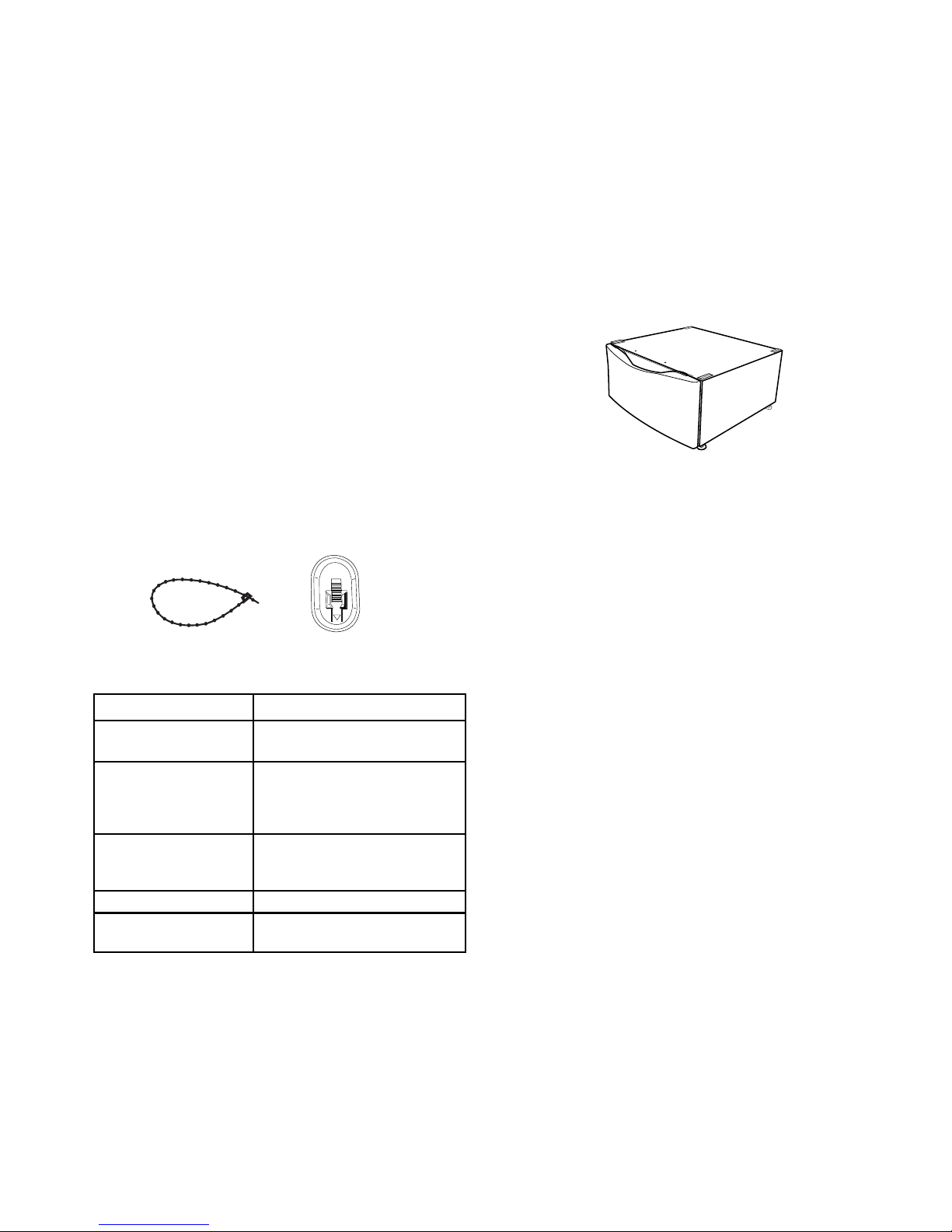
Parts supplied
Beaded Strap Transport Bolt Hole Plug (4)
Alternate parts
If You Have You Will Need To Buy
Laundry tub or standpipe
taller than 96″ (2.4 m)
Overhead sewer
Floor drain
Drain hose too short Drain hose extension kit #285863.
Water faucets beyond
reach of fill hoses
Sump pump system (if not already
available).
Standard 20 gal. (76 L), 30″
(76.2 cm) tall drain tub or utility
sink and sump pump (available from
local plumbing supplier).
Siphon break, #285834; additional
drain hose #8318155; and
connector kit #285835.
2 longer water fill hoses: 6′ (1.8 m)
#76314, 10′ (3.0 m) #350008.
OPTIONAL PEDESTAL
A pedestal (LAB2700PMT/LAB2700LQ) may
be purchased separately for this washer. This
pedestal will add about 13″ (33 cm) to the
height of the unit for a total vertical height of
approximately 51″ (130 cm).
Optional Pedestal
OPTIONAL STACK KIT
To stack your washer and dryer, you will need
to purchase Stack Kit, Part Number 8541503.
LOCATION REQUIREMENTS
Selecting the proper location for the washer
improves performance, and minimizes noise
and possible washer “walk.”
The washer can be installed under a custom
counter, or in a basement, laundry room, closet,
or recessed area (see “Drain System”).
Companion appliance location requirements
should also be considered. Proper installation
is your responsibility.
You will need
• A water heater set to deliver 120°F (49°C)
water to the washer.
• A grounded electrical outlet located within
5 ft. (1.5m) of where the power cord is
attached to the back of the washer (see
“Electrical Requirements”).
Continued on the next page.
2-1
• Hot and cold water faucets located within
4 ft. (1.2 m) of the hot and cold water fill
valves, and water pressure of 20-100 psi
(137.9-689.6 kPa).
• A level floor with a maximum slope of 1″
(2.5 cm) under entire washer. Installing the
washer on carpeting is not recommended.
• A sturdy and solid floor to support the washer
with a total weight (water and load) of 400
lbs. (180 kg).
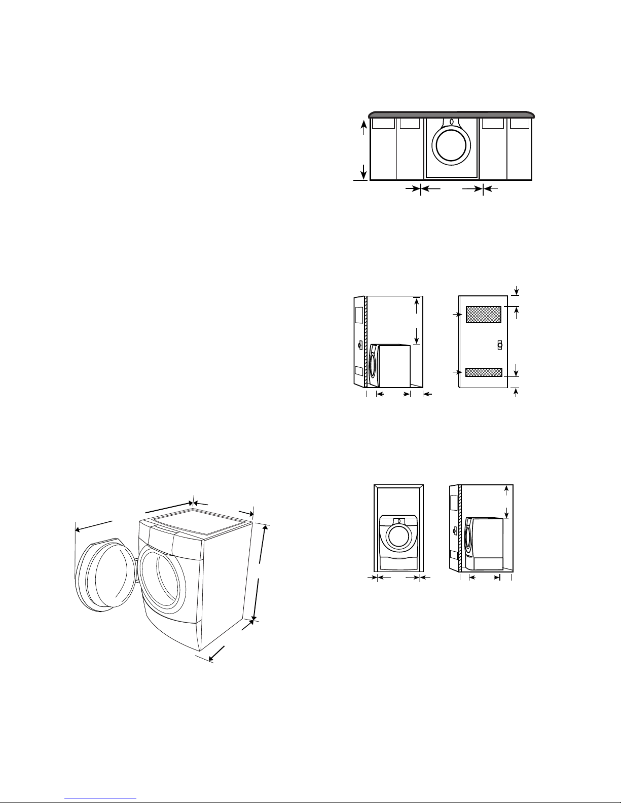
Custom Undercounter Installation
The dimensions shown are for the recommended spacing.
39" min
(99.0 cm)
1"
(2.5 cm)
27"
(68.6 cm)
1"
(2.5 cm)
Do not operate your washer in temperatures
below 32°F (0°C). Some water can remain in
the washer and can cause damage in low temperatures.
Installation Clearances
• The location must be large enough to allow
the washer door to be fully opened.
• Additional spacing should be considered for
ease of installation and servicing.
• Additional clearances might be required for
wall, door, and floor moldings.
• Additional spacing of 1″ (2.5 cm) on all sides
of the washer is recommended to reduce
noise transfer.
• Companion appliance spacing should also
be considered.
Washer Dimensions
27"
50-1/2"
(128.3 cm)
(68.6 cm)
Recessed Or Closet Installation
The dimensions shown are for the recommended spacing.
Recessed Area Or Closed Installation
3"
(7.6 cm)
3"
(7.6 cm)
1"
(2.5 cm)
(
31-1/2"
(80 cm)
1
86.4
34
"
cm)
4"
(10.2 cm)
48 in.
(310 cm
24 in.
(155 cm
2
2
)
2
2
)
2
1. Side view - closet or confined area
2. Closet door with vents
Recessed Or Closet Installation—
Washer On Pedestal
18 min."
(45.7 cm)
31-1/2"
(80.0 cm)
38"
(96.5 cm)
2-2
1"
(2.5 cm)
1. Recessed area
2. Side view - closet or confined area
27"
(68.6 cm)
(2.5 cm)
1"
1"
(2.5 cm)
31-1/2"
(80 cm)
21
4"
(10.2 cm)
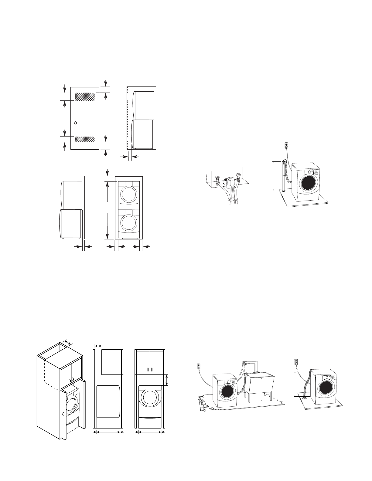
Recessed Or Closet Installation—
30" min.
(76.2 cm)
28" min.
(71 cm)
1
2
With Stacked Washer & Dryer
The dimensions shown are for the recommended spacing.
48 in.2 *
2
(310 cm
)
3" (7.6 cm)
3" (7.6 cm)
6" (15.2 cm)
76"
(193 cm)
1" (2.5 cm)
24 in.
(155 cm
2
*
2
)
DRAIN SYSTEM
The washer can be installed using the standpipe
drain system (floor or wall), the laundry tub
drain system, or the floor drain system. Select
the drain hose installation method you need
(see “Alternate Parts”).
Standpipe Drain System—
Wall Or Floor (View 1 & 2)
The standpipe drain requires a minimum diameter standpipe of 2″ (5 cm). The minimum
carry-away capacity can be no less than 17 gal
(64 L) per minute.
30" min.
(76.2 cm)
12
5-1/2"**
(14 cm)
* Min. top and bottom air openings for closet do or.
** External exhaust elbow requires additional space.
***Wall, door and floor molding may require
additional spacing.
1"***
(2.5 cm)
27"
(68.6 cm)
1"***
(2.5 cm)
Cabinet Installation
The dimensions shown are for the recommended spacing. For cabinet installation with
a door, the minimum ventilation openings in
the top are required.
7" (17.8 cm)
7" (17.8 cm)
9"
(22.9 cm)
The top of the standpipe must be at least 30″
(76.2 cm) high and no higher than 96″ (2.4 m)
from the bottom of the washer.
Laundry Tub Drain System (View 1)
The laundry tub needs a minimum 20 gal.
(76 L) capacity. The top of the laundry tub must
be at least 30″ (76.2 cm) above the floor.
Floor Drain System (View 2)
The floor drain system requires a siphon break
that may be purchased separately (see “Alternate Parts ”).
The siphon break must be a minimum of 28″
(71 cm) from the bottom of the washer. Additional hoses might be needed.
31-1/2"
4"
0.2 cm
)
(80.0 cm)
(1
1"
(2.5 cm)1"(2.5 cm)
27"
(68.6 cm)
1"
(2.5 cm)
2-3
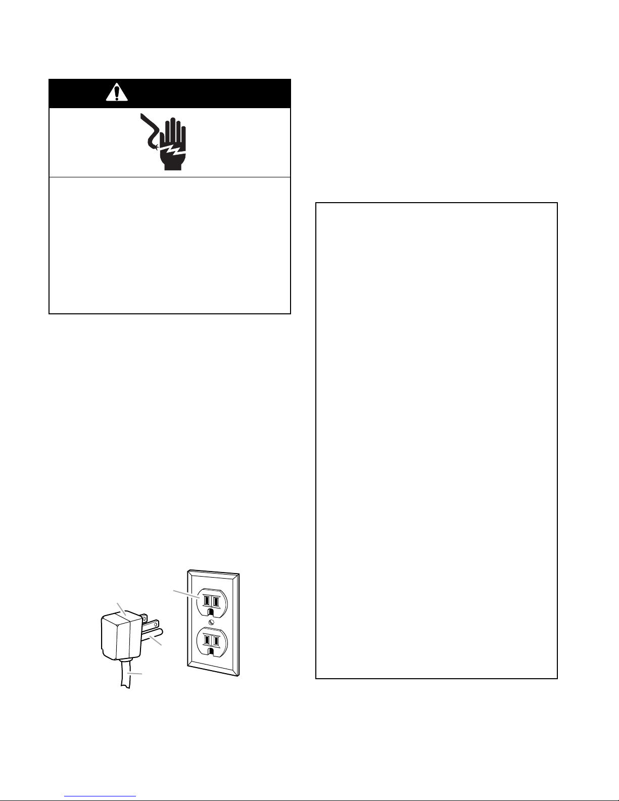
ELECTRICAL REQUIREMENTS
WARNING
Electrical Shock Hazard
• If codes permit and a separate ground wire
is used, it is recommended that a qualified
electrician determine that the ground path is
adequate.
• Do not ground to a gas pipe.
• Check with a qualified electrician if you are
not sure the washer is properly grounded.
• Do not have a fuse in the neutral or ground
circuit.
Plug into a grounded 3 prong outlet.
Do not remove ground prong.
Do not use an adapter.
Do not use an extension cord.
Failure to follow these instructions can
result in death, fire, or electrical shock.
• A 120-volt, 60-Hz., AC-only, 15- or 20-ampere, fused electrical supply is required. A
time-delay fuse, or circuit breaker, is recommended. It is recommended that a separate
circuit serving only this appliance be provided.
• This washer is equipped with a power supply
cord having a 3 prong grounding plug.
• To minimize possible shock hazard, the cord
must be plugged into a mating, 3 prong,
grounding-type outlet, grounded in accordance with local codes and ordinances. If a
mating outlet is not available, it is the personal responsibility and obligation of the
customer to have the properly grounded
outlet installed by a qualified electrician.
GROUNDING INSTRUCTIONS
For a grounded, cord-connected
washer:
This washer must be grounded. In the event
of a malfunction or breakdown, grounding
will reduce the risk of electrical shock by
providing a path of least resistance for electric current. This washer is equipped with a
cord having an equipment-grounding conductor and a grounding plug. The plug must
be plugged into an appropriate outlet that is
properly installed and grounded in accordance with all local codes and ordinances.
WARNING: Improper connection of the
equipment-grounding conductor can result
in a risk of electric shock. Check with a
qualified electrician or serviceman if you are
in doubt as to whether the appliance is
properly grounded.
Do not modify the plug provided with the
appliance. If it will not fit the outlet, have a
proper outlet installed by a qualified electrician.
2
1
3
4
1. 3 prong grounding plug
2. 3 prong grounding-type wall receptacle
3. Grounding prong
4. Power supply cord
For a permanently connected washer:
This washer must be connected to a grounded
metal, permanent wiring system, or an equipment-grounding conductor must be run with
the circuit conductors and connected to the
equipment-grounding terminal or lead on the
appliance.
2-4
INSTALLATION INSTRUCTIONS
Installing The Washer
REMOVE TRANSPORT SYSTEM
WARNING
Excessive Weight Hazard
Use two or more people to move and
install washer.
Failure to do so can result in back or
other injury.
IMPORTANT: Position the washer so that the
rear of the unit is within approximately 3 feet
(90 cm) of the final location.
There are 4 bolts in the rear panel of the washer
that support the suspension system during
transportation. These bolts also retain the power
cord inside the washer until the bolts are removed. To remove the bolts:
1. Using a 1/2″ (13 mm) wrench, loosen each
of the bolts.
4. Close the bolt holes with the four transport
bolt hole plugs.
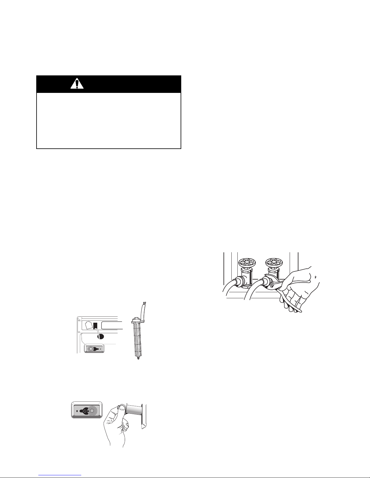
CONNECT THE INLET HOSES
Connect the inlet hoses to the water faucets.
Make sure the washer basket is empty.
1. Using a pair of pliers, check the tightness
of the hose couplings that are attached to
the washer. NOTE: Do not overtighten the
couplings, or damage to the coupling can
result.
2. Attach the hose with the red color indicator
to the hot water faucet, and the hose with
the blue color indicator to the cold water
faucet. Screw on the couplings by hand
until they are seated on the washer.
3. Using a pair of pliers, tighten the couplings
an additional two-thirds turn. NOTE: Do
not overtighten the couplings, or damage
to the coupling can result.
2. Once the bolt is loose, move it to the center
of the hole, and completely pull out the
bolt, including the plastic spacer covering
the bolt, and the cable attached to the bolt.
The power cord will be attached to all 4
bolts inside the washer.
3. Once all 4 bolts are removed, pull the
power cord through the opening of the rear
panel, and close the hose with the attached cap.
4. Turn on the water and check the couplings
for leaks.
NOTE: Replace the inlet hoses after 5 years of
use to reduce the risk of hose failure. Record
the hose installation, or replacement dates on
the hoses for future reference. Periodically
inspect and replace hoses if bulges, kinks,
cuts, wear, or leaks are found.
2-5
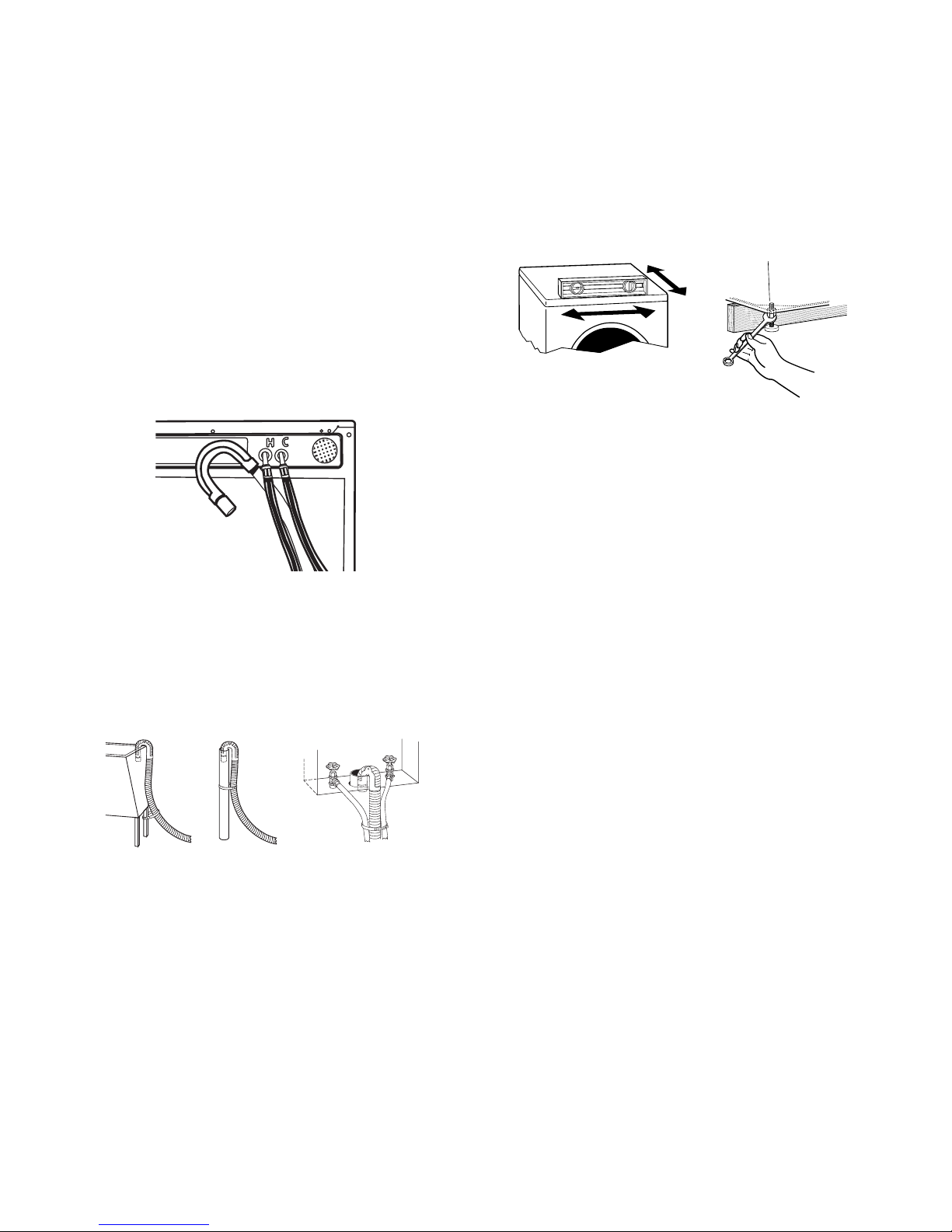
ROUTE THE DRAIN HOSE
LEVEL THE WASHER
The drain hose is connected to your washer.
Proper routing of the drain hose protects your
floors from damage due to water leakage.
Carefully read and follow these instructions.
To prevent drain water from going back into
the washer:
• Do not straighten the drain hose, and do not
force excess drain hose into the standpipe.
The hose should be secure, but loose enough
to provide a gap for air.
• Do not lay excess hose on the bottom of the
laundry tub.
Properly leveling your washer prevents excessive noise and vibration. To level the washer:
1. Check the levelness of the washer by
placing a level on the top edge of the
washer, first side-to-side, then front-toback.
If the washer is against a wall, move the
washer out slightly before tipping back. If
the washer is not level, first prop the front
with a wood block (2″ x 4″) and adjust the
feet as necessary; then prop the back and
adjust feet as necessary. Repeat this step
until washer is level.
SECURE THE DRAIN HOSE
1. Drape the power cord over the washer top.
2. Secure the drain hose to the laundry tub
leg, or to the standpipe with the beaded
strap that is provided.
1
2
If the washer faucets and the drain
standpipe are recessed, place the hooked
end of the drain hose in the standpipe.
Tightly wrap the beaded strap around the
water inlet and drain hoses.
NOTE: Do not force excess drain hose into the
standpipe.
3
2. After the washer is level, use a 5/8″ (17
mm) open-end wrench to turn the nuts on
the feet tightly against the washer cabinet.
All 4 feet must be tightened. If the nuts are
not tight against the washer cabinet, the
washer may vibrate.
3. Slide the washer to its final location.
4. Confirm the levelness of the washer.
COMPLETE THE INSTALLATION
1. Check the electrical requirements. Be sure
that you have the correct electrical supply
and the recommended grounding method
(see “Electrical Requirements”).
2. Check to be sure all parts are now installed. If there is an extra part, go back
through the steps to see which step was
skipped.
3. Check to be sure you have all of your tools.
4. Dispose/recycle all packaging materials.
5. Check to be sure the water faucets are on.
6. Check for leaks around faucets and inlet
hoses.
7. Plug into a grounded 3 prong outlet.
2-6

INSTALLING THE WASHER ON THE PEDESTAL
23-5/8"
(60 cm)
18-9/16"
(47.2 cm)
2-5/8"
(6.7 cm)
27"
(68.6 cm)
IMPORTANT: Check that all 4 pads are
present as shown. If they are not, do not
install the pedestal, and contact your dealer.
13"
(33 cm)
UNINSTALLING THE WASHER
WARNING
Excessive Weight Hazard
Use two or more people to move and
uninstall washer.
Failure to do so can result in back or
other injury.
IMPORTANT: If the washer is already installed,
it must be uninstalled. See Installation Instructions that came with the washer for tools required.
1. Turn off the hot and cold water to the
washer.
2. Unplug the power supply cord.
3. Slowly loosen the fill hoses at the faucets
to relieve the water pressure.
4. Remove the “HOT” and “COLD” fill hoses
from the back of the washer. Drain water
in the hoses into a bucket.
5. Squeeze the ears of the drain hose clamp
with pliers to open and slide the clamp
down the hose. Disconnect the drain hose
from the washer and drain any water in the
hose into a bucket.
6. Pull the washer away from the wall so it
can be tipped on its back.
7. Protect the floor with a large piece of
cardboard cut from the pedestal carton.
Lay the washer on its back so that the
cardboard is under the entire lower back
edge of the washer.
2-7
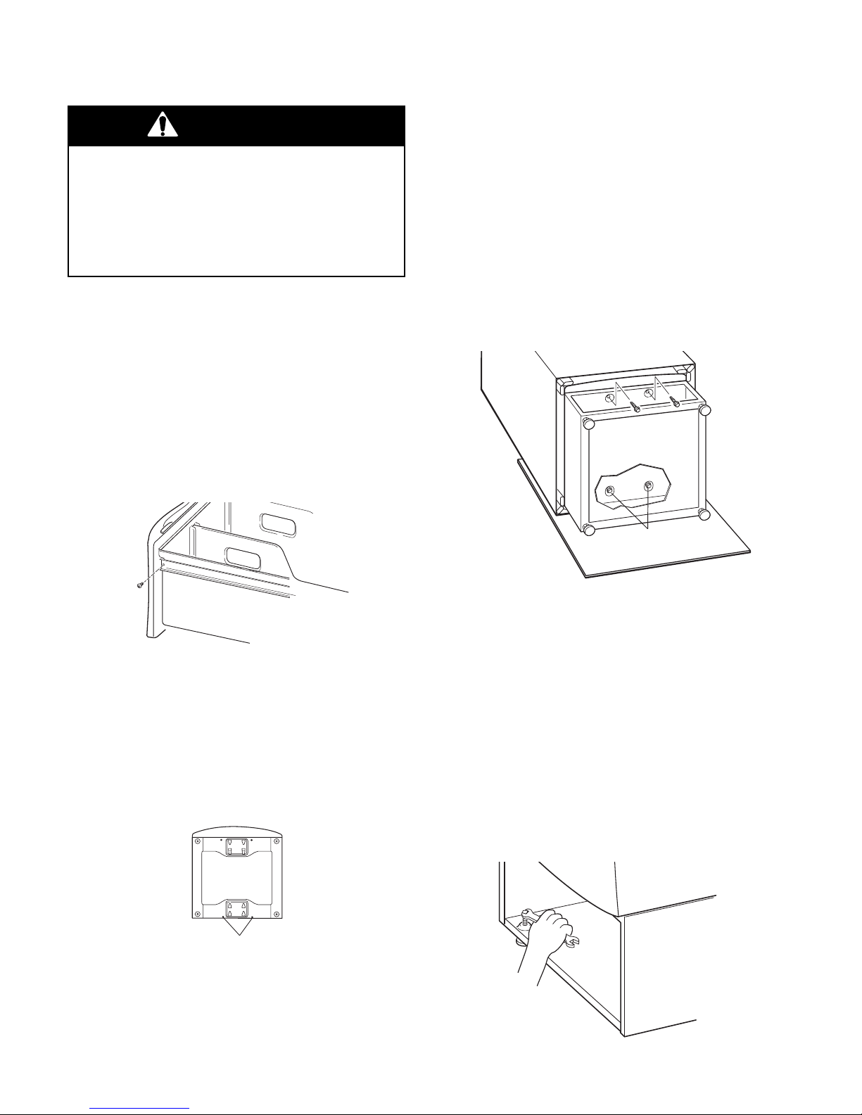
INSTALLING THE PEDESTAL
WARNING
5. Move the pedestal against the washer
bottom, and slide the pedestal’s keyhole
slots over the lower two partially installed
screws.
Excessive Weight Hazard
Use two or more people to move and
install pedestal.
Failure to do so can result in back or
other injury.
1. Open the pedestal drawer, and remove
the envelope taped inside the drawer.
This envelope contains four (4) #12 x 5/8″
(1.6 cm) hex-head sheet metal screws
that will be used in step 4.
2. Remove the phillips screw from both
drawer slides and save the screws. Remove the drawer from the slides and set it
aside. Push the drawer slides back into
the pedestal.
Position the pedestal toward the front of
the washer and install the two remaining
hex-head sheet metal screws. Do not
tighten completely.
Align the sides of the pedestal so that they
are even with the sides of the washer.
Reach inside the pedestal drawer opening, and securely tighten all four pedestal
screws.
lower screws in
keyhole slots
3. Remove the four feet from the washer, but
DO NOT install the feet that were supplied
with the new washer.
4. Partially install the two lower hex-head
sheet metal screws. Leave a space of
about 3/8″ (1 cm) between the screw head
and the bottom of the washer.
Washer Bottom
Install Screws
6. Tip the washer and pedestal assembly
back to an upright position and remove
protective cardboard.
7. Slide the washer close to its final location.
8. Follow the Installation Instructions that
were supplied with the washer, and finish
installing or reinstalling the unit.
9. Locate the 1/4″ hex nut on the top of each
pedestal foot. Reach inside the pedestal
and use a ratchet or open-end wrench,
and adjust the feet up or down, as necessary to level the washer and pedestal.
2-8
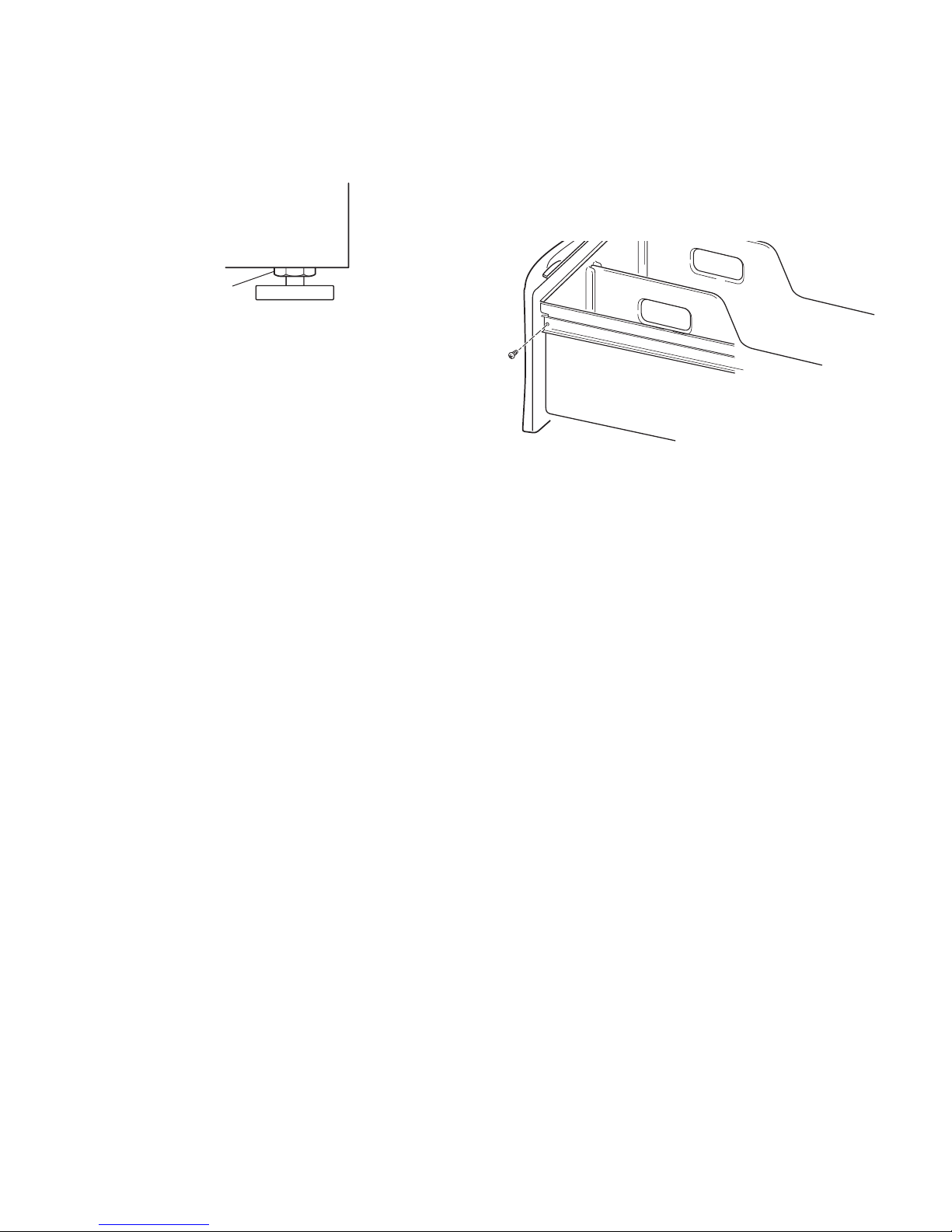
10. When the washer is level, use a 9/16″
open-end wrench to securely tighten the
locknuts on all four feet against the pedestal.
locknut
11. Pull both drawer slides out and reassemble the drawer to the drawer slides
with the two (2) phillips screws you removed earlier. NOTE: Use of the two (2)
dividers is optional.
12. Close the pedestal drawer.
2-9

— NOTES —
2-10

PRODUCT OPERATION
THEORY OF OPERATION
INTRODUCTION
The KitchenAid Ensemble Front-Loading Automatic Washer presents a number of new
features and operating characteristics quite
different from previous models. In addition to
the introduction of front-loading operation, the
washer contains a number of unique operating
features designed to increase clothes cleaning
ability while offering very high water and energy conservation.
WATER SYSTEM
The water system consists of the hot and cold
water inlet valves, a water temperature sensor,
a water flowmeter and control, and the dispenser distribution system along with a traditional pressure switch.
WATER INLET VALVES
The hot and cold water inlet valves are located
at the back of the washer. These valves receive a control signal from the Central Control
Unit to manage the temperature of incoming
water. The temperatures are determined by
the specific wash cycle selected and a temperature sensor located in the wash tub. To
improve cleaning of heavily soiled clothing and
to provide a sanitizing feature, the water temperature can be increased through the use of a
heating element located in the bottom of the
tub.
The flowmeter is also used to introduce additional water into the tub for higher water levels,
based on cycle requirements.
Flowmeter
DISPENSER DISTRIBUTION
SYSTEM
All wash and rinse water is introduced into the
wash tub through a Dispenser Distribution System located in the top left corner of the washer.
The system consists of a motor that turns a
cam gear. The cam follower will divert the
incoming water to one or more of the follow
water inlet modes:
• Detergent Dispensing
• Bleach Dispensing
• Fabric Softener Dispensing
• Rinse Dispensing (no additives)
Dispenser
Motor
FLOWMETER
Water flow, or the quantity of water introduced
throughout any cycle, is monitored by a flowmeter and Central Control Unit. When the
flowmeter registers a maximum of 10.5 gal
(40 L), and the Central Control Unit has not
detected the pressure switch trip, the water
valves will be shut off and an error code will
show in the digital display.
3-1
Cam
Follower
Water
Distribution
Lever
Cam
Actuator

The dispenser drawer has four separate compartments for adding laundry products to the
wash load. These compartments are:
1. Prewash Detergent Compartment
2. Main Wash Detergent Compartment
3. Bleach Compartment
4. Fabric Softener Compartment
The water enters the wash tub through the
main inlet tube.
Main Inlet
Tube
1
2
3
4
Laundry products are diluted and dispensed
automatically at the proper time during the
wash cycle. The separator in the Prewash and
Main Wash Detergent Compartment can be
moved to accommodate either liquid or powdered detergents.
The drawer release lever can be installed in the
stack position to accommodate stacking a
matching dryer on top of the washer.
Release Lever
Stack Position
Release Lever
AIR VENT SYSTEM
As a safety feature, the washer is designed to
allow fresh air to circulate through the tub. An
inlet vent at the rear of the washer brings air
into the tub. The fresh air is vented through the
dispenser assembly vent tube and out the front
of the dispenser drawer cutout.
Air Vent
Vent Tube
Vent Tube
3-2
PRESSURE SWITCH
The pressure switch is located in the top right
rear corner of the washer. This switch senses
water level in the wash tub. The control signal
from the pressure switch is sent to the Central
Control Unit and is used to determine the
amount of water introduced into the wash tub
during the wash cycle.
The pressure switch also senses the suds level
in the wash tub. If excessive sudsing occurs,
the washer starts an automatic suds routine.
The display will show the word “Sud.” The
automatic suds routine adds additional rinse
and drain operations until the suds level is
reduced.
If an overfill condition is detected by the pressure switch, the CCU will turn on the drain
pump and attempt to stop filling.
Pressure Switch
3-3

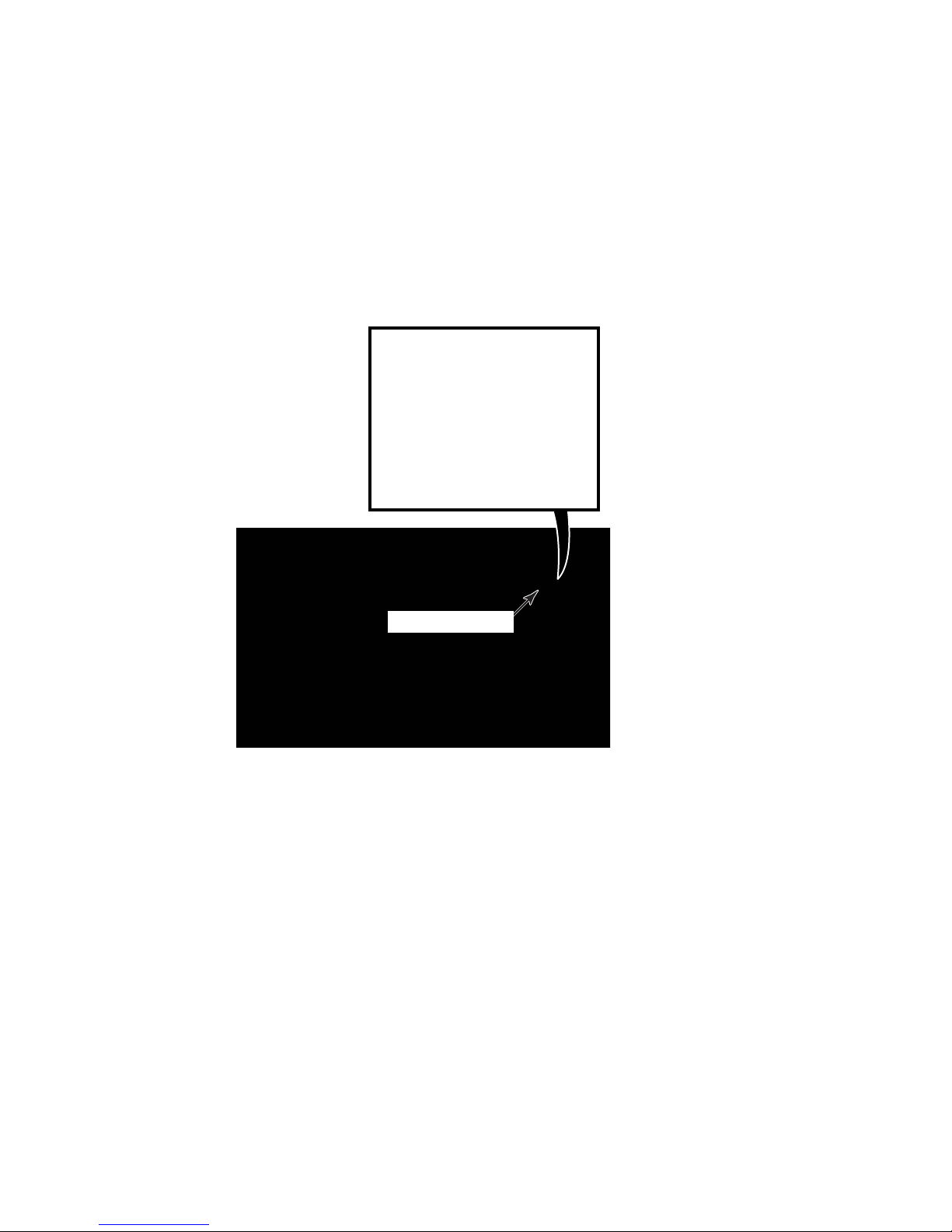
TOUCH PAD/LED ASSEMBLY
MOTOR CONTROL UNIT (MCU)
The Touch Pad/LED Assembly is removed as
a single assembly and is connected to the
Central Control Unit by a ribbon cable. This
assembly contains all of the buttons, LEDs and
ribbon cable and printed circuit boards for the
user to operate the washer. This interfaces the
consumer inputs to the Central Control Unit.
Ribbon Cable
Touchpad/LED
Assembly
CENTRAL CONTROL UNIT (CCU)
The Central Control Unit is located at the top
rear of the washer and is enclosed in a control
box. There are no serviceable parts inside the
control box. If diagnostic tests indicate any
component of the CCU is defective, the entire
control box must be replaced.
The CCU receives input from the touchpad/
LED assembly and directly controls the dispenser, drain pump, water inlet valves, door
locking and unlocking solenoids, and heating
element relay. The CCU monitors the pressure
switch, flowmeter, temperature sensor and door
lock switches.
The CCU sends the customer selection input to
the Motor Control Unit for proper motor operation.
The Motor Control Unit is located inside a
plastic control box located in the lower front
corner of the washer cabinet. The control box
is shown with the access door open.
The MCU operates the drive motor at varying
speeds and direction based on inputs received
by the CCU to complete the cycle selected.
The MCU also monitors a tachometer on the
motor to confirm that the drive motor is operating at the proper speed and direction.
Motor Control Unit
DRIVE MOTOR
The drive motor is a three-phase asynchronous induction type that operates at various
speeds and direction based on input voltages
and frequencies. A tachometer on the motor
shaft sends a feedback signal to the Motor
Control Unit indicating the rotation speed and
direction.
Drive Motor
Central Control Unit
3-4
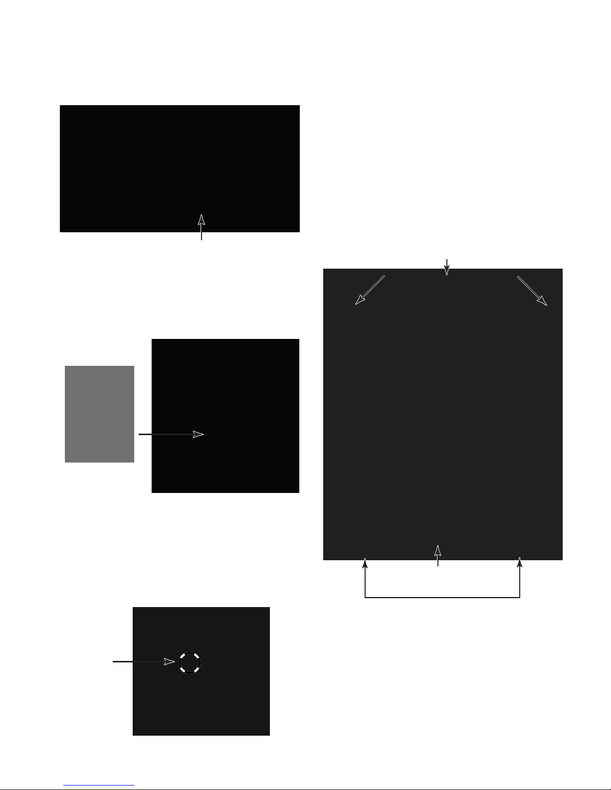
PUMP MOTOR
SUSPENSION SYSTEM
A separate pump/pump motor is used to drain
the wash tub.
Pump Motor
The pump motor is 120 VAC and is attached
directly to the pump. The pump has a cleanout
filter located at the front that allows for the
removal of large objects that may have passed
from the basket.
The wash tub is held in position with four shock
absorbers attached to the bottom four corners
of the tub assembly. In addition, the wash tub
is suspended from the top frame of the washer
with two springs attached to the sides of the
unit.
Stability for this suspension system is provided
by three concrete counter weights. Two are
located at the front of the wash tub. One is
positioned at the back of the tub. These counter
weights eliminate the need for the traditional
balance ring.
Top Front Counterweight
Spring
Spring
Large Object
Filter
ECO VALVE
The washer has a specially designed floating
(ball) valve that closes during the wash portion
of the cycle so that 100% of the water and
detergent mixture is used on the wash load.
The Eco Valve insures that no water or detergent is wasted.
Floating
(Ball) Valve
Bottom Front Counterweight
Front Shock Absorbers
3-5
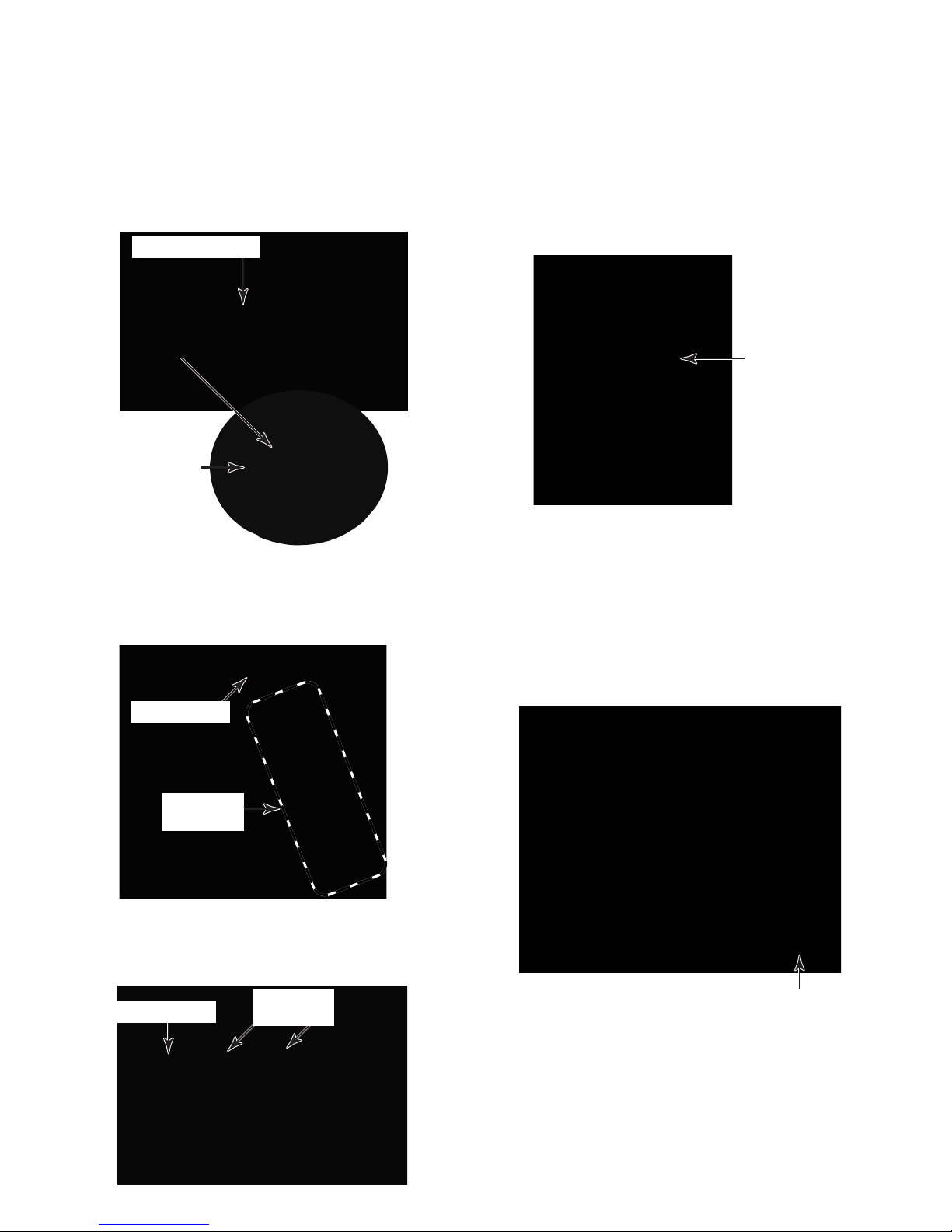
HEATING ELEMENT &
TEMPERATURE SENSOR
A heating element is used to increase the water
temperature during certain wash cycles. The
temperature sensor is used with the heater to
monitor water temperature in the tub.
Heating Element
Temperature
Sensor
HEATING ELEMENT RELAY
A relay is used to turn the heating element on
and off. The heating element relay is located in
the lower right-hand side of the washer cabinet. The CCU operates a solenoid to close the
main relay contacts, providing 120 VAC to the
heating element.
Heating
Element Relay
INTERLOCK SWITCHES
DOOR LOCK/SWITCH ASSEMBLY
The Door Lock/Switch Assembly is located on
the right side of the door opening.
Door Switch
Door Lock
Switches
The assembly contains a solenoid operated
latching mechanism that will electrically lock
the door during a wash cycle.
Door Switch
Door Lock
Switches
The front and rear interlock switches are located immediately behind the toe and rear
panels of the washer. The switches provide a
grounding circuit to the drive motor and heating
element when either panel is removed for
servicing.
Rear Interlock Switch
3-6
CUSTOMER INTERFACE & CYCLE SELECTION
Control On - This button must be pressed
before initiating any cycle selection.
Status Indicators - Show which portion of the
cycle the washer is operating. They also indicate when additional items can be added to the
wash cycle and when the controls are locked.
Wash Cycle Selector - Selects the various
Wash Cycles. Each cycle is designed for different types of fabric and soil levels (see the
“Preset Cycle Settings”- table on Page 3-9).
Display - Provides information, such as the
time remaining for selected wash cycle and
various error codes.
Control On
Display
Soil Level - Changes the length of the wash
cycle. “+” will add time to a normal wash cycle;
“–” will shorten a normal wash cycle.
Hold-To-Start - Initiates a wash cycle. Press
and hold the START button for one second.
OFF/Pause - Pressing this button will allow
changing any option, or changing a wash cycle
after the wash cycle has begun. Press the
OFF/Pause button, select the desired option,
and press and hold the START button for
1 second. To cancel a cycle and select a new
one, press the OFF/Pause button, select the
new cycle, select the desired options, and
press and hold the START button for 1 second.
Hold To Start
Status Indicators
Wash Cycle
Selector
Soil Level
(Change Any Time)
Off/Pause
3-7

CYCLES
Sanitary - Cleans heavily soiled colorfast fab-
rics. This cycle combines a super hot water
temperature and fast speed tumbling to help
ensure the removal of heavy soils and stains.
It is recommended that you set your hot water
heater to 120°F (49°C) to ensure proper performance during this cycle. The Sanitary cycle
also helps kill bacteria, even when no bleach is
used. Extra high speed spin helps shorten
drying time.
Whitest Whites - Designed for cleaning loads
of soiled white fabrics with the addition of
bleach. Hot washing temperatures assure optimal bleach activity. An additional rinse provides optimal rinse performance to avoid chlorine residues on your laundry. This cycle combines fast speed tumbling, longer wash time,
and extra high speed spin to shorten drying
time.
Heavy Duty - Washes loads of sturdy, colorfast fabrics, and heavily to normally soiled
garments. This cycle combines fast speed
tumbling, longer wash time, and extra high
speed spin to shorten drying times. If the water
temperature is lower than needed for this cycle,
the heater will warm the water to the optimum
temperature.
Normal/Casual - Washes normally soiled cottons and linens. This cycle combines medium
speed tumbling and high speed spin.
Rapid Wash - Washes small loads of lightly
soiled garments that are needed in a hurry.
This cycle combines fast speed tumbling, a
shortened wash time, and extra high speed
spin to shorten drying time.
Delicate - Washes no-iron fabrics in garments
labeled “Permanent Press,” or “Wrinkle Free,”
or that indicate using a “Gentle” cycle on the
care label. This cycle combines low speed
tumbling and low speed spin to reduce wrinkling.
Silk - Cleans washable silk garments. (Check
label instructions to make sure that garment is
washable.) This cycle gently tumbles and drains
without spinning to gently clean garments and
minimize wrinkling. Since there is no spinning
action, garments will contain a higher amount
of water at the end of this cycle.
Wool - Cleans washable woolen garments.
(Check label instructions to make sure that garment is washable.) This cycle features gentle
tumbling and low speed spin to provide optimum garment care.
Handwash - Cleans hand-washable and special-care garments. Similar to the way garments are hand washed in a sink, the wash
action of this cycle combines periods of low
speed tumbling and soaking. The low speed
spin reduces wrinkling.
3-8
 Loading...