

KitchenAid KHWL260VSS0, KHWL260VWH0, KHWC260VCR0, KHWC260VSS0, KHWG260VCR0 Installation Guide
...
I_itc enAid _
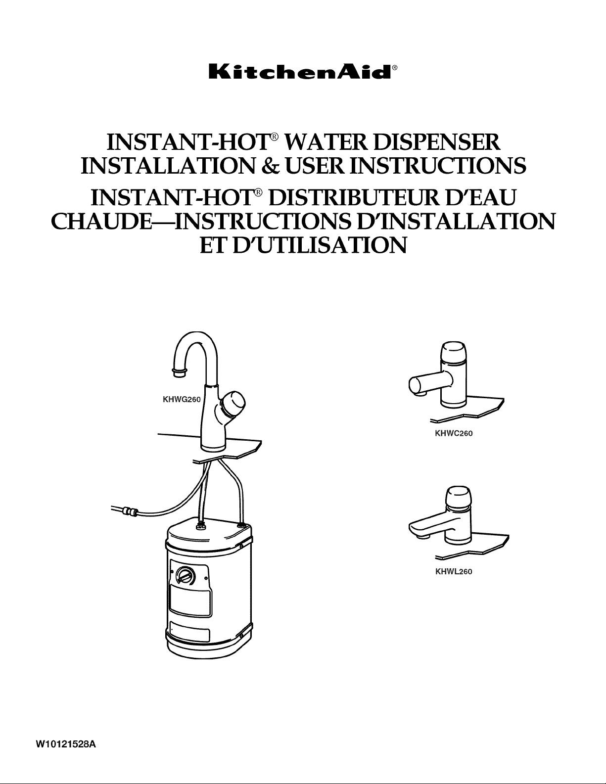
INSTANT-HOT* WATER DISPENSER
INSTALLATION & USER INSTRUCTIONS
INSTANT-HOT _DISTRIBUTEUR D'EAU
CHAUDE_INSTRUCTIONS D'INSTALLATION
ET D'UTILISATION
KHWC260
KHWL260
W10121528A
TABLEOF CONTENTS
HOT WATER DISPENSER SAFETY .............................................. 2
INSTALLATION REQUIREMENTS ................................................ 3
Tools and Parts ............................................................................ 3
Location Requirements ................................................................ 3
Electrical Requirements ............................................................... 4
Water Supply Requirements ........................................................ 5
INSTALLATION INSTRUCTIONS .................................................. 5
Inspect Shipment ......................................................................... 5
Install the Faucet .......................................................................... 5
Install the Tank ............................................................................. 6
Complete Installation ................................................................... 7
HOT WATER DISPENSER USE ..................................................... 8
Flush Hot Water Dispenser Tank Before Use .............................. 8
Set the Temperature ..................................................................... 8
Dispense Hot Water ..................................................................... 8
HOT WATER DISPENSER CARE .................................................. 9
Prepare Hot Water Dispenser for Nonuse ................................... 9
TROUBLESHOOTING .................................................................. 10
ASSISTANCE OR SERVICE ......................................................... 11
In the U.S.A ................................................................................ 11
In Canada ................................................................................... 11
WAR RANTY .................................................................................. 12
TABLEDES MATIERES
SI_CURITI_ DU DISTRIBUTEUR D'EAU CHAUDE ..................... 13
EXIGENCES D'INSTALLATION ................................................... 13
Outillage et pieces ...................................................................... 14
Exigences d'emplacement ......................................................... 14
Specifications electriques .......................................................... 15
Specifications de I'alimentation en eau ..................................... 16
INSTRUCTIONS D'INSTALLATION ............................................ 16
Inspection de I'appareil livre...................................................... 16
Installation du robinet ................................................................. 16
Installation du reservoir .............................................................. 17
Achever I'installation .................................................................. 18
UTILISATION DU DISTRIBUTEUR D'EAU CHAUDE ................ 19 GARANTIE ..................................................................................... 23
Vidange du reservoir du distributeur d'eau
chaude avant usage ................................................................... 19
Reglage de la temperature ......................................................... 19
Distribution d'eau chaude .......................................................... 19
ENTRETIEN DU DISTRIBUTEUR D'EAU CHAUDE ................... 20
Preparation du distributeur d'eau chaude
en vue d'une periode de non-utilisation .................................... 20
DI_PANNAGE ................................................................................. 21
ASSISTANCE OU SERVICE ......................................................... 22
Aux €:tats-Unis ............................................................................ 22
Au Canada .................................................................................. 22
HOT WATER DISPENSER SAFETY
Your safety and the safety of others are very important.
We have provided many important safety messages in this manual and on your appliance. Always read and obey all safety
messages.
This is the safety alert symbol.
This symbol alerts you to potential hazards that can kill or hurt you and others.
All safety messages will follow the safety alert symbol and either the word "DANGER" or "WARNING."
These words mean:
You can be killed or seriously injured if you don't immediately
follow instructions.
You can be killed or seriously injured if you don't follow
instructions.
All safety messages will tell you what the potential hazard is, tell you how to reduce the chance of injury, and tell you what can
happen if the instructions are not followed.
iMPORTANT SAFETY iNSTRUCTiONS
WARNING: To reduce the risk of fire, electrical shock or injurywhen using your hot water dispenser, follow these basic precautions:
[] Plug into a grounded 3 prong outlet. [] Do not use an extension cord.
[] Do not remove ground prong. [] Disconnect power before servicing.
[] Do not use an adapter.
SAVE THESE INSTRUCTIONS
2
INSTALLATION REQUIREMENTS
These instructions are intended as a general guide only for use by
qualified persons and do not supersede any national or local
codes in any way. Compliance with all local, state, or national
codes pertaining to this type of equipment should be determined
prior to installation.
Read this entire instruction manual, as well as the instructions
supplied in separate equipment, before starting the installation.
This hot water dispenser is not a water purifier. Some installations
may require a water filtering system to improve the quality of the
water.
Gather the required tools and parts before starting installation.
Read and follow the instructions provided with any tools listed
here.
Tools Needed
• Adjustable wrench with • Pliers
minimum opening of 1V2"
(3.8 cm) • Tube cutter
• Phillips screwdriver • 1A"or 7 mm open-end
• Tape measure • Bucket or pan
• Pencil
Faucet for the hot water dispenser requires a 1%" (3.5 cm)
diameter opening in the sink or countertop. Faucet can be
installed in the existing opening for a sink spray hose. If the
faucet is not to be installed in the sink spray hose opening or
another existing opening, it is recommended that a qualified
installer be contacted to drill the hole through your sink or
countertop. Thickness of the sink or countertop must not exceed
13/4"(4.4 cm).
Cold water supply connection must be available. See "Water
Supply Requirements."
wrench
Parts Needed
• Screws or anchors for attaching the mounting bracket to
the wall
1/4"(6.4 mm) O.D. copper or plastic tube
Saddle valve kit or other plumbing parts needed to connect
1/4"(6.4 mm) tube from the faucet easy-connect fitting to
the water supply line. If a saddle valve is used, do not use a
piercing type or 3/16"(4.8 mm) saddle valve, which reduces
water flow and clogs more easily.
NOTE: Saddle valve kit or other plumbing parts used must
meet all local plumbing codes and ordinaces.
Parts Supplied
Remove parts from packages. Check that all parts were included.
• Faucet assembly • Tank mounting bracket
• Water tank • Hose clamp
Grounded 3 prong outlet is required. See "Electrical
Requirements." The outlet should be located within 42"
(106.7 cm) of the hot water dispenser tank.
Plumbing connections must comply with all sanitary and
plumbing codes.
Water connections use easy-connect fittings which do not
require sealing compounds.
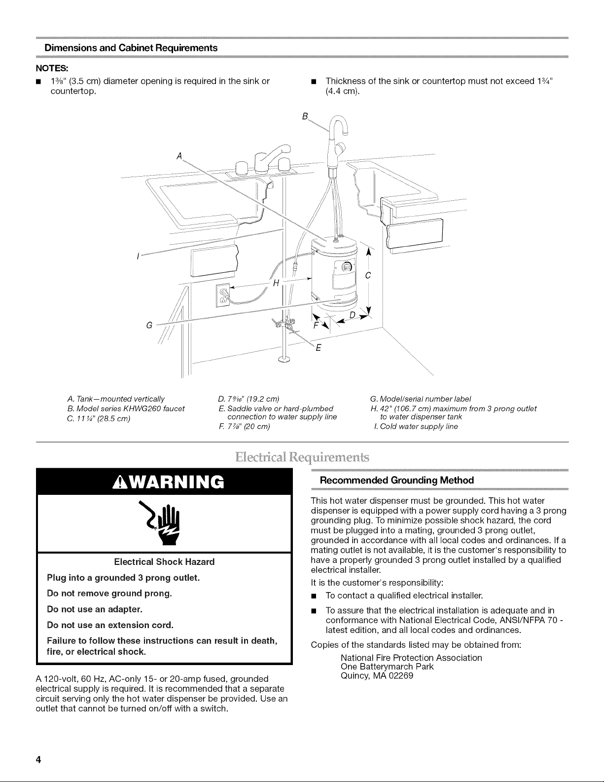
Dimensions and Cabinet Requirements
NOTES:
• 13/8"(3.5 cm) diameter opening is required in the sink or • Thickness of the sink or countertop must not exceed 13/4''
countertop. (4.4 cm).
C
i
i '
G
A. Tank--mounted vertically
B. Model series KHWG260 faucet
C. 11¼" (28.5 cm)
D. 7_" (19.2 cm)
E. Saddle valve or hard-plumbed
connection to water supply line
F. 7_" (20 cm)
Electrical Shock Hazard
Plug into a grounded 3 prong outlet.
Do not remove ground prong.
Do not use an adapter.
Do not use an extension cord.
Failure to follow these instructions can result in death,
fire, or electrical shock.
A 120-volt, 60 Hz, AC-only 15- or 20-amp fused, grounded
electrical supply is required. It is recommended that a separate
circuit serving only the hot water dispenser be provided. Use an
outlet that cannot be turned on/off with a switch.
\\\\\
\\
\
\
\\
G. Model/serial number label
H. 42" (106.7 cm) maximum from 3 prong outlet
to water dispenser tank
I. Cold water supply line
Recommended Grounding Method
This hot water dispenser must be grounded. This hot water
dispenser is equipped with a power supply cord having a 3 prong
grounding plug. To minimize possible shock hazard, the cord
must be plugged into a mating, grounded 3 prong outlet,
grounded in accordance with all local codes and ordinances. If a
mating outlet is not available, it is the customer's responsibility to
have a properly grounded 3 prong outlet installed by a qualified
electrical installer.
It is the customer's responsibility:
• To contact a qualified electrical installer.
• To assure that the electrical installation is adequate and in
conformance with National Electrical Code, ANSI/NFPA 70 -
latest edition, and all local codes and ordinances.
Copies of the standards listed may be obtained from:
National Fire Protection Association
One Batterymarch Park
Quincy, MA 02269
Iflocalcodespermit,thehotwaterdispenserfaucettubeshould
beconnectedto1/4"(6.4mm)tube(notprovided),whichis
connectedtothecoldwatersupplylineusingasaddlevalve(not
provided)oranothermeanstoconnectthe1/4"(6.4mm)tubeto
thecoldwatersupplyline.Ifasaddlevalveisused,donotusea
piercingtypeor3A6"(4.8mm)saddlevalve,whichreduceswater
flowandclogsmoreeasily.
IM PORTANT:
• If local codes do not permit the use of saddle valves, special
feed valves can be obtained from your local plumbing supply
distributor.
Connection to the hot water line is not recommended. Energy
will be wasted in heating the water twice and may produce an
undesirable taste.
• A water filter is recommended if your water supply contains
sand, grit or other particles, or has a known taste or odor
issue. If a water filter system is used, the water pressure to
the hot water dispenser system from the filter needs to be a
minimum of 20 psi (138 kPa) for proper operation.
• If the water pressure to the hot water dispenser system is less
than 20 psi (138 kPa), performance may be affected.
INSTALLATION INSTRUCTIONS
This hot water dispenser is shipped in one package. • If damage is found, it should be noted on the carrier's freight
Upon receipt of the hot water dispenser, inspect it for
possible shipping damage. Examine the hot water dispenser
inside the carton if the carton is damaged.
NOTE: The hot water dispenser is not a water purifier. Some
installations may require a water filtering system to improve the
quality of the water.
1. Determine the final location of the hot water dispenser faucet.
Check below the sink to verify that reinforcing ribs, support
brackets or cabinet construction will not interfere with the hot
water dispenser faucet.
2. To prepare the sink or countertop for installation, perform one
of the following:
• Remove the plug from the sink.
• Use an existing opening inthe sink or countertop.
• Cut a hole in the sink or countertop.
NOTE: It is recommended that only a licensed plumber or
professional installer should cut a hole in the sink or
countertop.
3.
Straighten tube so that it will go through the hole in the sink
or countertop.
4.
Remove the nut, metal washer and rubber washer from the
faucet.
NOTE: Do not remove the rubber O-ring in the bottom of the
faucet base.
bill. Damage claims should be filed with the carrier
immediately. Claims of shortages should be filed with the
seller within 5 days.
NOTE: If any damages are discovered and reported to the carrier,
do not install the hot water dispenser, because your claim may be
denied.
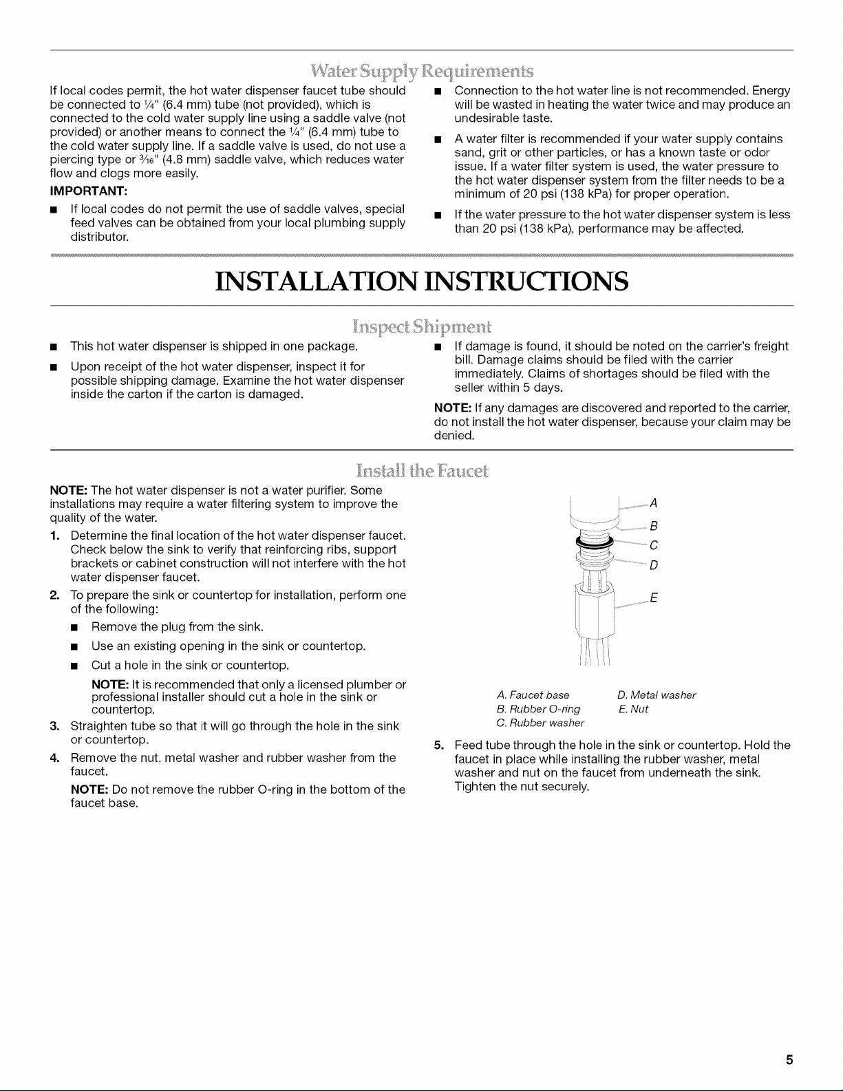
I:l-l:Icel:
A. Faucet base D. Metal washer
B. Rubber O-ring E.Nut
C. Rubber washer
5,
Feed tube through the hole in the sink or countertop. Hold the
faucet in place while installing the rubber washer, metal
washer and nut on the faucet from underneath the sink.
Tighten the nut securely.
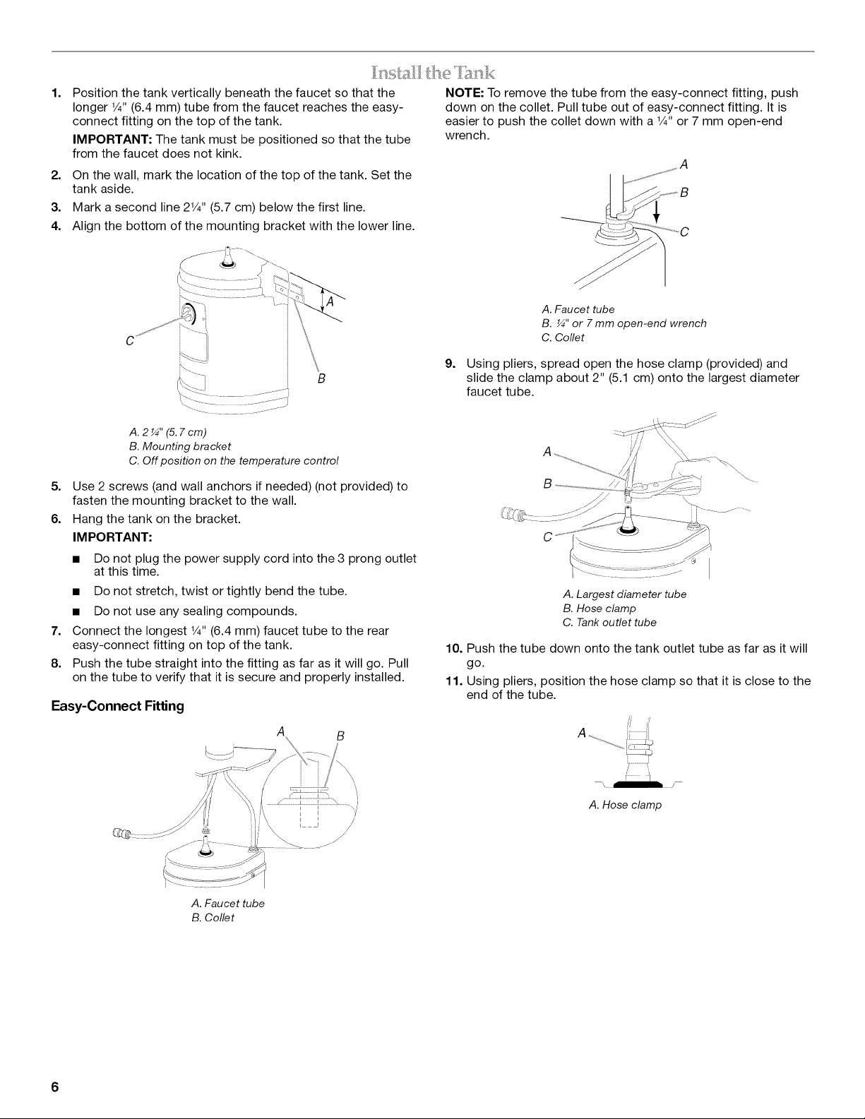
1=
Position the tank vertically beneath the faucet so that the
longer 1/4"(6.4 mm) tube from the faucet reaches the easy-
connect fitting on the top of the tank.
IMPORTANT: The tank must be positioned so that the tube
from the faucet does not kink.
2. On the wall, mark the location of the top of the tank. Set the
tank aside.
3. Mark a second line 21/4"(5.7 cm) below the first line.
4. Align the bottom of the mounting bracket with the lower line.
U
A. 2_" (5.7cm)
B. Mounting bracket
C. Off position on the temperature control
5. Use 2 screws (and wall anchors if needed) (not provided) to
fasten the mounting bracket to the wall.
6. Hang the tank on the bracket.
IM PORTANT:
• Do not plug the power supply cord into the 3 prong outlet
at this time.
• Do not stretch, twist or tightly bend the tube.
• Do not use any sealing compounds.
7. Connect the longest 1/4"(6.4 mm) faucet tube to the rear
easy-connect fitting on top of the tank.
8. Push the tube straight into the fitting as far as it will go. Pull
on the tube to verify that it is secure and properly installed.
Easy-Connect Fitting
NOTE: To remove the tube from the easy-connect fitting, push
down on the collet. Pull tube out of easy-connect fitting. It is
easier to push the collet down with a 1/4"or 7 mm open-end
wrench.
A. Faucet tube
B. _" or 7 mm open-end wrench
C. Collet
9=
Using pliers, spread open the hose clamp (provided) and
slide the clamp about 2" (5.1 cm) onto the largest diameter
faucet tube.
A. Largest diameter tube
B. Hose clamp
C. Tank outlet tube
10. Push the tube down onto the tank outlet tube as far as it will
go.
11. Using pliers, position the hose clamp so that it is close to the
end of the tube.
\
A. Hose clamp
A. Faucet tube
B. Collet
6
12. Install the saddle valve kit or other plumbing parts as needed
to connect the 1/4"(6.4 mm) tube from the faucet easy-
connect fitting to the cold water supply line.
13. Flush the line into a bucket or pan to remove any debris that
may have been trapped in the supply line during plumbing
connection.
14. Check that the water flows freely and that there are no leaks.
15. Connect the 1/4"(6.4 mm) water supply line tube to the faucet
tube with the factory-assembled easy-connect fitting. Push
the water supply line tube straight into the fitting as far as it
will go. Pull on the tube to verify that it is secure and properly
installed.
Factory Assembled Easy-Connect Fitting
NOTE: To remove the tube from the easy-connect fitting, push
down on the collet. Pull tube out of easy-connect fitting. It is
easier to push the collet down with a 1/4"or 7 mm open-end
wrench.
A. Faucet tube
B. _" or 7 mm open-end wrench
C. Coflet
IMPORTANT: For proper operation, do not remove the factory-
assembled easy-connect fitting from the tube.
IMPORTANT: The hot water dispenser can be damaged if the
following steps are not followed.
NOTE: Do not connect the hot water dispenser to the power
supply at this time.
1. Turn the Temperature Control counterclockwise to the Off
position.
2=
Push down and turn the faucet cap clockwise to open the
faucet. Hold the cap inthis position until water flows from the
faucet (approximately 1 to 11/2minutes). Water flowing from
the faucet signals that the hot water dispenser tank is filled.
16. Open the water line to the faucet.
17. Check for leaks.
3. Release faucet cap.
4. Check for leaks.
NOTE: Make sure the Temperature Control is in the Off position
before connecting the hot water dispenser to the power supply. If
the tank is empty and the Temperature Control is in the On
position when the power is connected, the hot water dispenser
will overheat, and permanently damage the hot water dispenser.
Electrical Shock Hazard
Plug into a grounded 3 prong outlet.
Do not remove ground prong.
Do not use an adapter.
Do not use an extension cord.
Failure to follow these instructions can result in death,
fire, or electrical shock.
A
A. Faucet cap--Model series KHWG260
5=
Plug power supply cord into a grounded 3 prong outlet.
6.
Turn the Temperature Control clockwise to the highest
position. Water in the hot water dispenser tank will reach
maximum temperature in approximately 15 minutes.
NOTES:
• You may hear gurgling noises coming from the tank while the
water is heating. This is normal.
• A small amount of hot water may flow from the faucet while
the water is heating. This is normal for the first time heating of
the dispenser.
• The Temperature Control does not control the water delivery.
Push down and turn the faucet cap clockwise to control the
water delivery.
HOT WATER DISPENSER USE
• The Temperature Control regulates the water heating
temperature. Rotate the Temperature Control clockwise to
raise the water temperature, or counterclockwise to lower the
water temperature.
• Turn the Temperature Control to a lower setting if vapor is
appearing near the faucet or if you hear the sound of water
boiling.
NOTE: Before using the hot water from the hot water dispenser 3.
for the first time, allow the hot water dispenser to heat the water
for approximately 15 minutes. 4.
1. Push down and turn the faucet cap clockwise to open the 5.
faucet.
2. Allow the water to run for approximately 1 minute to flush hot
water dispenser tank.
The water temperature is thermostatically controlled using the
Temperature Control. The Temperature Control can be set to a
maximum temperature of 190°F (88°C) (approximate).
1. To raise the water temperature, turn the Temperature Control
clockwise.
Z To lower the water temperature, turn the Temperature Control
counterclockwise.
NOTE: The Max setting is recommended for best performance.
Turn the Temperature Control to a lower setting if vapor appears
near the faucet or if you hear the sound of water boiling.
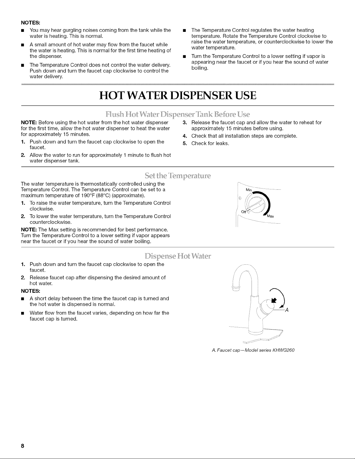
)}iot' W!£:w
1. Push down and turn the faucet cap clockwise to open the
faucet.
2. Release faucet cap after dispensing the desired amount of
hot water.
NOTES:
• A short delay between the time the faucet cap is turned and
the hot water is dispensed is normal.
• Water flow from the faucet varies, depending on how far the
faucet cap is turned.
Release the faucet cap and allow the water to reheat for
approximately 15 minutes before using.
Check that all installation steps are complete.
Check for leaks.
A. Faucet cap--Model series KHWG260
8
 Loading...