

KitchenAid KHTU765RSS1, KHTU705RSS1 Owner’s Manual
®itchenAid ®
(91.4cm)
et 36" (91,4 cm)
avec
Table of Contents/Table des mati_res ............................................................................. 2
iMPORTANT: READ AND SAVE THESE iNSTRUCTiONS,
FOR RESiDENTiAL USE ONLY.
iMPORTANT : LIRE ET CONSERVER CES iNSTRUCTiONS,
POUR UTiLiSATiON RESmDENTmELLEUNiQUEMENT.
iMPORTANT:
Installer: Leave installation instructions with the homeowner,
Homeowner: Keep installation instructions for future reference.
Save installation instructions for local inspector's use,
iMPORTANT :
lnetallateur : Remettre les instructions d'installation au proprietaire.
PropriStaire : Conserver les instructions d'installation pour consultation ulterieure.
Conserver les instructions d'instatlation pour consultation par I'inspecteur local.
9763384
TABLEOF CONTENTS TABLEDES ' TIERES
RANGE HOOD SAFETY ............................... 2
iNSTALLATiON REQUIREMENTS ....................... 3
Tools and Parts ..................................... 3
Location Requirements ............................. 4
Venting Requirements .............................. 4
Electrical Requirements ............................. 5
INSTALLATION INSTRUCTIONS ........................ 6
Venting Options ................................... 6
Prepare Location .................................. 6
Change Hood to Rear Exhaust ....................... 7
install Range Hood ................................ 8
Make Electrical Connection .......................... 8
Optional Front Trim installation ....................... 9
install Filters ...................................... 9
Check Operation .................................. 9
RANGE HOOD USE ................................... 9
Range Hood Controls .............................. 9
RANGE HOOD CARE ................................ 10
Range Hood Lamps ............................... 10
Replacing Hood Lamps Fuse ....................... 10
Cleaning ........................................ 10
Accessories ..................................... 11
REQUESTING ASSISTANCE OR SERVICE .............. 11
RANGE HOOD WARRANTY ........................... 12
WIRING DIAGRAM .................................. 13
S#CURITE DE LA HOTTE DE CUISINI_:RE .............. 14
EXIGENCES D'INSTALLATION ........................ 16
Outillage et pi6ces .................................. 16
Exigences d'emplacement .......................... 16
Ex[gences concernant I'evacuation ................... 17
Specifications ebctriques .......................... 18
INSTRUCTIONS D'INSTALLATION ..................... 19
Options disponibles pour Ie circuit d'evacuation ........ 19
Preparation de Femplacement ....................... 19
Modification de Ia hotte pour evacuation par
I'arri_re (facultatif) ................................ 20
installation de Ia hotte de cu[s[n[_re .................. 21
Raccordement electrique ........................... 21
installation de Ia garniture de fagade
interchangeable (option) ........................... 22
installation des filtres .............................. 22
Contr61e du fonctionnement ........................ 22
UTIUSATION DE LA HOTTE DE CUISINI :RE............ 23
Commandes de la hotte de cuisini_re ................. 23
ENTRETIEN DE LA HOTTE DE OUISINI_:RE ............. 23
Lampes de la hotte de cuisini_re ..................... 23
Remplacement des fusibles des lampes de la hotte ..... 23
Nettoyage ....................................... 24
Accessoires ..................................... 24
ASSISTANCE OU SERVICE ........................... 25
GARANTIE DE LA HOTTE DE CUISINIERE .............. 26
SCHEMA DE CABLAGE .............................. 27
RANGEHOODSAFETY
Your safety and the safety of others are very important.
We have provided many important safety messages in this manual and on your appliance. Always read and obey all safety
messages.
This is the safety alert symbol.
This symbol alerts you to potential hazards that can kill or hurt you and others.
All safety messages will follow the safety alert symbol and either the word "DANGER" or "WARNING."
These words mean:
You can be killed or seriously injured if you don't immediately
follow instructions.
You can be killed or seriously injured if you don't follow
instructions.
All safety messages will tell you what the potential hazard is, tell you how to reduce the chance of injury, and tell you what can
happen if the instructions are not followed.
iMPORTANT SAFETY iNSTRUCTiONS
WARNING: TO REDUCE THE RiSK OF FIRE, ELECTRIC
SHOCK, OR iNJURY TO PERSONS, OBSERVE THE
FOLLOWING:
m Use this unit only in the manner intended by the
manufacturer, if you have questions, contact the
manufacturer.
m Before servicing or cieaning the unit, switch the power off at
the service panel disconnecting means to prevent power
from being switched on accidentalIy. When the service
disconnecting means cannot be locked, securely fasten a
prominent warning device, such as a tag, to the service
panel.
m installation work and electricaJ wiring must be done by
qualified person(s) in accordance with all applicable codes
& standards, including fire-rated construction.
m Sufficient air is needed for proper combustion and
exhausting of gases through the flue (chimney) of fuel
burning equipment to prevent backdrafting. Follow the
heating equipment manufacturer's guideline and safety
standards such as those published by the National Fire
Protection Association (NFPA), the American Society for
Heating, Refrigeration and Air Conditioning Engineers
(ASHRAE), and the local code authorities.
m When cutting or drilling into wall or ceiling; do not damage
electrical wiring and other utilities.
m Ducted systems must always be vented outdoors.
CAUTION: For general ventilating use only. Do not use
to exhaust hazardous or explosive materials and vapors.
CAUTION: To reduce risk of fire and to properly exhaust
air, be sure to duct air outside - do not vent exhaust air into
spaces within walls ceilings, attics, crawl spaces, or
garages.
WARNING: TO REDUCE THE RiSK OF FIRE, USE ONLY
METAL DUCTWORK.
WARNING: TO REDUCE THE RiSK OF A RANGE TOP
GREASE FIRE:
m Never leave the surface units unattended at high settings.
Boilovers cause smoking and greasy spillovers that may
ignite. Heat oils siowiy on low or medium settings.
m Always turn hood ON when cooking at high heat or when
flameing food (i.e. Crepes Suzette, Cherries Jubilee,
Peppercorn Beef Flamb@.
m Clean ventilating fans frequently. Grease shouId not be
allowed to accumulate on fan or filter.
m Use proper pan size. Always use cookware appropriate for
the size of the surface element.
WARNING: TO REDUCE THE RiSK OF iNJURY TO
PERSONS iN THE EVENT OF A RANGE TOP GREASE
FIRE, OBSERVE THE FOLLOWING: a
m SMOTHER FLAMES with a close fitting Iid, cookie sheet, or
other metal tray, then turn off the gas burner or electric
element. BE CAREFUL TO PREVENT BURNS. if the
flames do not go out immediately, EVACUATE AND CALL
THE FiRE DEPARTMENT.
m NEVER PiCK UP A FLAMING PAN - you may be burned.
m DO NOT USE WATER, including wet dishcloths or towels -
a vioIent steam explosion wilI result.
m Use an extinguisher ONLY if:
- You know you have a class ABC extinguisher, and you
already know how to operate it.
- The fire is small and contained in the area where it
started.
- The fire department is being called.
- You can fight the fire with your back to an exit.
aBased on "Kitchen Fire Safety Tips" published by NFPA.
m WARNING: To reduce the risk of fire or electrical shock,
do not use this fan with any solid-state speed control
device.
SAVE THESE iNSTRUCTiONS
INSTALLATIONREQUIREMENTS
Gather the required tools and parts before starting installation.
Read and follow the safety instructions provided with any tools
listed here.
Tools needed:
Level
Drill
11//, drill bit
Pencil
Pliers
Wire stripper or utility knife
Tape measure or ruler
Caulking gun and weatherproof caulking compound
Saber or keyhole saw
Duct tape
Flat-blade screwdriver
Metal snips
Phillips screwdriver
7 mm nut driver or socket
Parts supplied
Check that all parts are included.
4 screws
4 wall anchors
Damper
Parts needed
UL listed or CSA approved 1/2"(12.5 mm) strain reliefs (2)
Power supply cable
6" (15.2 cm) round wall or roof cap
6" (15.2 cm) metal vent system
IMPORTANT:Observeallgoverningcodesandordinances,
Itistheinsta/er'sresponsibilitytocomplywithinstallation
clearancesspecifiedonthemodel/serialratingplate,The
model/serialratingplateislocatedinsidetherangehoodon
therearwall.
Rangehoodlocationshouldbeawayfromstrongdraftareas,
suchaswindows,doorsandstrongheatingvents.
Cabinetopeningdimensionsthatareshownmustbeused.
Givendimensionsprovideminimumclearance.Consuityour
cooktop/rangemanufacturerinstallationinstructionsbefore
makinganycutouts.
Groundedelectricaloutletisrequired.See"Electrical
Requirements"section.
Thehoodisfactorysetforventedinstallations.For
recircuiatinginsta/ations,RecirculationKitPartNumber
4896565,includingventcoverand2charcoalfiltersare
availablefromyourdealer.
AIopeningsinceilingandwallwhererangehoodwillbe
installedmustbesealed.
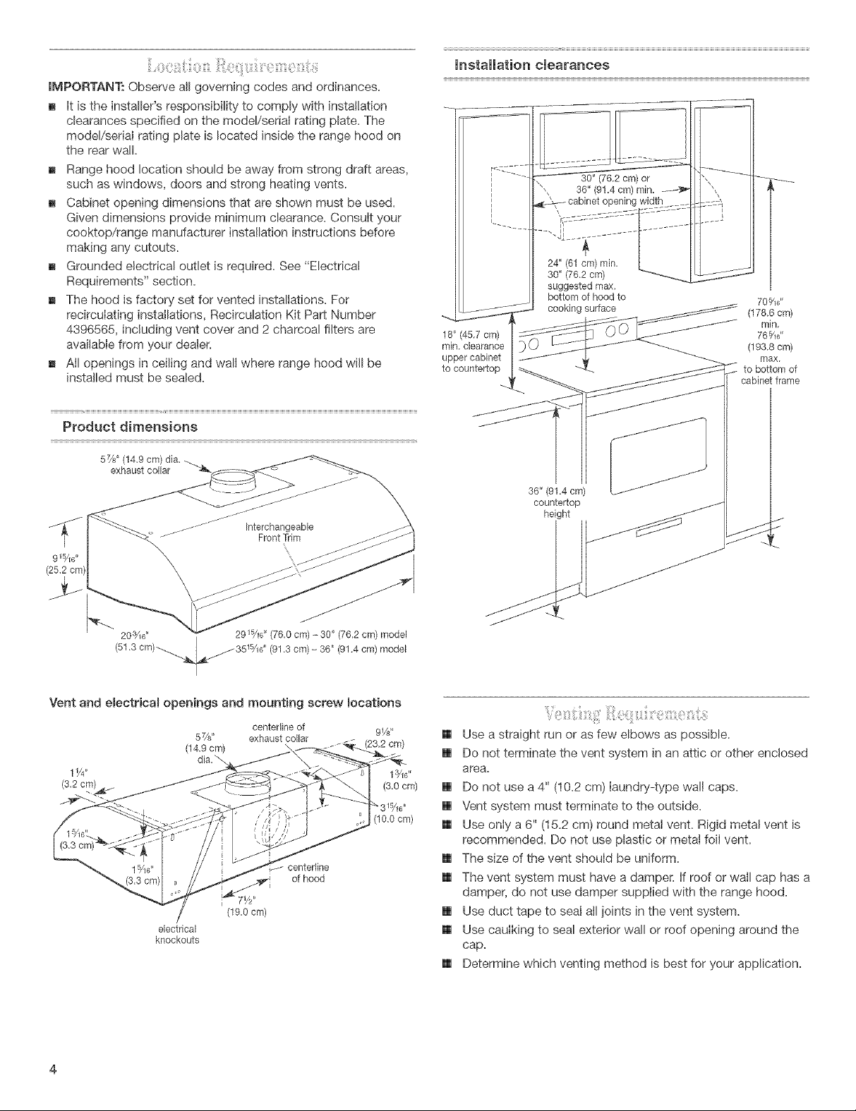
Productdimensions
57/s' (14,9 cm) dia,
exhaust collar
J J" Interchangeable
_f Front Trim
installation clearances
bottom of hood to 70%d
(178,6 cm)
18" (45.7 cm) 76%d
rain, clearance (193.8 cm)
upper cabinet max,
to countertop to bottom of
36" (91,4 cm)
countertop
height
rain.
cabinet frame
Vent and electrical openings and mounting screw locations
5 x/s" exhaust collar
(14.9 cm) (23,2 cm)
dia,'_,
electrical
knockouts
centerlne of 9V8"
(10.0cm)
centerlne
of hood
(19,0 cm)
[] Use a straight run or as few elbows as possible.
[] Do not terminate the vent system in an attic or other enclosed
area.
[] Do not use a 4" (10.2 cm) [aundry-type wal caps.
[] Vent system must terminate to the outside.
[] Use only a 6" (15.2 cm) round metal vent. Rigid metal vent is
recommended. Do not use plastic or metal foil vent.
[] The size of the vent shouid be uniform.
[] The vent system must have a damper, if roof or wall cap has a
damper, do not use damper suppled with the range hood.
[] Use duct tape to seaI a/ioints in the vent system.
[] Use cauiking to seal exterior wail or roof opening around the
cap.
[] Determine which venting method is best for your application.
ForBestPerformance:
[] Donotinstall2elbowstogether.
[] Usenomorethanthree90°elbows.
[] Ifanelbowisused,installitasfarawayaspossiblefromthe
hood'sventmotorexhaustopening.
[] Makesurethereisaminimumof24"(61cm)ofstraightvent
betweentheelbowsifmorethanoneelbowisused.
[] Thelengthofventsystemandnumberofelbowsshouldbe
kepttoaminimumtoprovideefficientperformance.
ColdWeatherlnetalmatione
Anadditionalbackdraftdampershouldbeinstalledtominimize
backwardcoldairflowandanonmetallicthermalbreakinstalled
tominimizeconductionofoutsidetemperaturesaspartofthe
ventsystem.Thedampershouldbeonthecoldairsideofthe
thermalbreak.
MakeupAir
Localbuildingcodesmayrequiretheuseofmakeupairsystems
whenusingventilationsystemsgreaterthanspecifiedCFMofair
movement.ThespecifiedCFMvariesfromlocaletolocale.
ConsultyourHVACprofessionalforspecificrequirementsinyour
area,
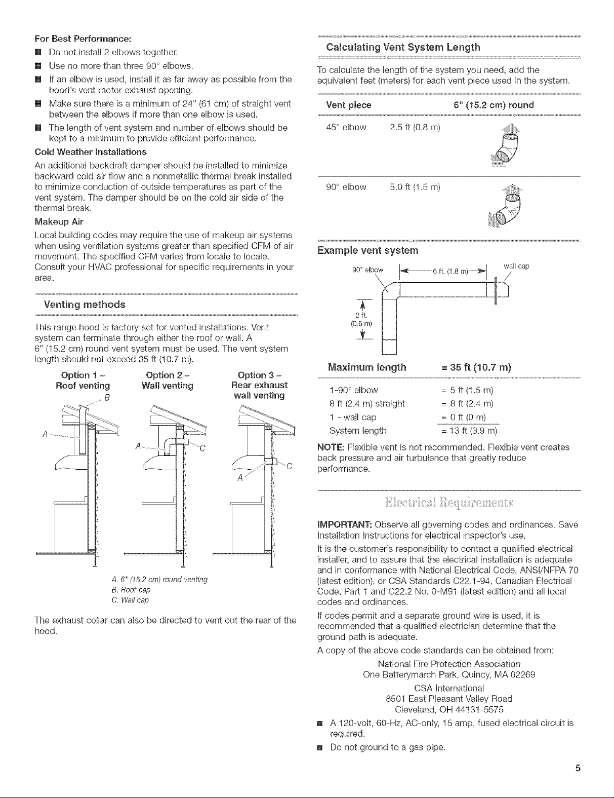
Calculating Vent System Length
To calculate the length of the system you need, add the
equivalent feet (meters) for each vent piece used in the system.
Vent piece 6" (15.2 cm) round
45° elbow 2.5 ft (0.8 m) _ ....
i
90° elbow 5.0 ft (1.5 m)
E×ample vent system
90° elbow _- 6 ft, (1.8 m)_'_ wall cap
\ /
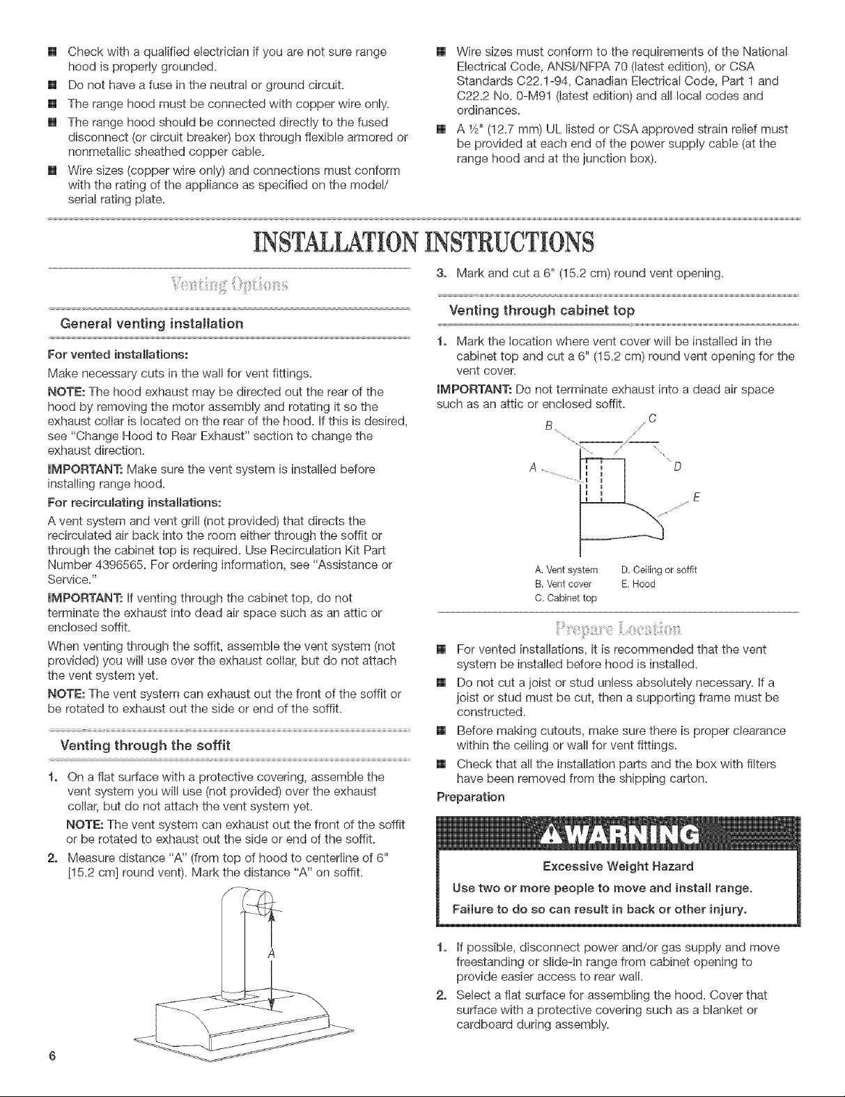
Venting methods
This range hood is factory set for vented installations. Vent
system can terminate through either the roof or wall. A
6" (15.2 cm) round vent system must be used. The vent system
length should not exceed 35 ft (10.7 m).
Option 1 - Option 2
Roof venting Wall venting
A. 6" (15.2 cn'_)round venting
B. Roof cap
C. Waftcap
The exhaust collar can also be directed to vent out the rear of the
hood.
Option 3 -
Rear exhaust
wall venting
A .....
2fL
(0_6rn)
Maximum _ength = 35 ft (10.7 m)
1-90 ° elbow = 5 ft (1.5 m)
8 ft (2.4 m) straight = 8 ft (2.4 m)
1 - wall cap = 0 ft (0 m)
System length = 13 ft (3.9 m)
NOTE: Flexible vent is not recommended. Flexible vent creates
back pressure and air turbulence that greatly reduce
performance.
IMPORTANT.- Observe all governing codes and ordinances. Save
installation instructions for electrical inspector's use.
it is the customer's responsibility to contact a qualified electrical
installer, and to assure that the electrical installation is adequate
and in conformance with National Electrical Code, ANSI/NFPA 70
(latest edition), or CSA Standards C22.1-94, Canadian Electrical
Code, Part 1 and C22.2 No. 0-M91 (latest edition) and all local
codes and ordinances.
if codes permit and a separate ground wire is used, it is
recommended that a qualified electrician determine that the
ground path is adequate.
A copy of the above code standards can be obtained from:
National Fire Protection Association
One Batterymarch Park, Quincy, MA 02269
CSA international
8501 East Pleasant Valley Road
Cleveland, OH 44131-5575
A 120-volt, 60-Hz, AC-only, 15 amp, fused electrical circuit is
required.
Do not ground to a gas pipe.
[] Checkwithaqualifiedelectricianifyouarenotsurerange
hoodisproperlygrounded.
[] Donothaveafuseintheneutralorgroundcircuit.
[] Therangehoodmustbeconnectedwithcopperwireonly.
[] Therangehoodshouldbeconnecteddirectlytothefused
disconnect(orcircuitbreaker)boxthroughflexiblearmoredor
nonmetallicsheathedcoppercable.
[] Wiresizes(copperwireonly)andconnectionsmustconform
withtheratingoftheapplianceasspecifiedonthemodel/
serialratingplate.
iNSTALLATiONiNSTRUCTiONS
[] WiresizesmustconformtotherequirementsoftheNational
ElectricalCode,ANSI/NFPA70(latestedition),orCSA
StandardsC22.1-94,CanadianElectricalCode,Part1and
C22.2No.0-M91(latestedition)andalllocalcodesand
ordinances.
[] A1/2"(12.7mm)ULlistedorCSAapprovedstrNnreliefmust
beprovidedateachendofthepowersupplycable(atthe
rangehoodandatthejunctionbox).
3. Mark and cut a 6" (15.2 cm) round vent opening.
GeneraJ venting installation
For vented instalmations:
Make necessary cuts in the wall for vent fittings.
NOTE: The hood exhaust may be directed out the rear of the
hood by removing the motor assembly and rotating it so the
exhaust collar is located on the rear of the hood. If this is desired,
see "Change Hood to Rear Exhaust" section to change the
exhaust direction.
IMPORTANT: Make sure the vent system is installed before
installing range hood.
For reeireumating installations:
A vent system and vent grill (not provided) that directs the
recirculated air back into the room either through the soffit or
through the cabinet top is required. Use Recirculation Kit Part
Number 4396565. For ordering information, see "Assistance or
Service."
IMPORTANT: If venting through the cabinet top, do not
terminate the exhaust into dead air space such as an attic or
enclosed soffit.
When venting through the soffit, assemble the vent system (not
provided) you will use over the exhaust collar, but do not attach
the vent system yet.
NOTE: The vent system can exhaust out the front of the soffit or
be rotated to exhaust out the side or end of the soffit.
Venting through the soffit
1. On aflat surface with a protective covering, assemble the
vent system you will use (not provided) over the exhaust
collar, but do not attach the vent system yet.
NOTE: The vent system can exhaust out the front of the soffit
or be rotated to exhaust out the side or end of the soffit.
2. Measure distance "A" (from top of hood to centerline of 6"
[15.2 cm] round vent). Mark the distance "A" on soffit.
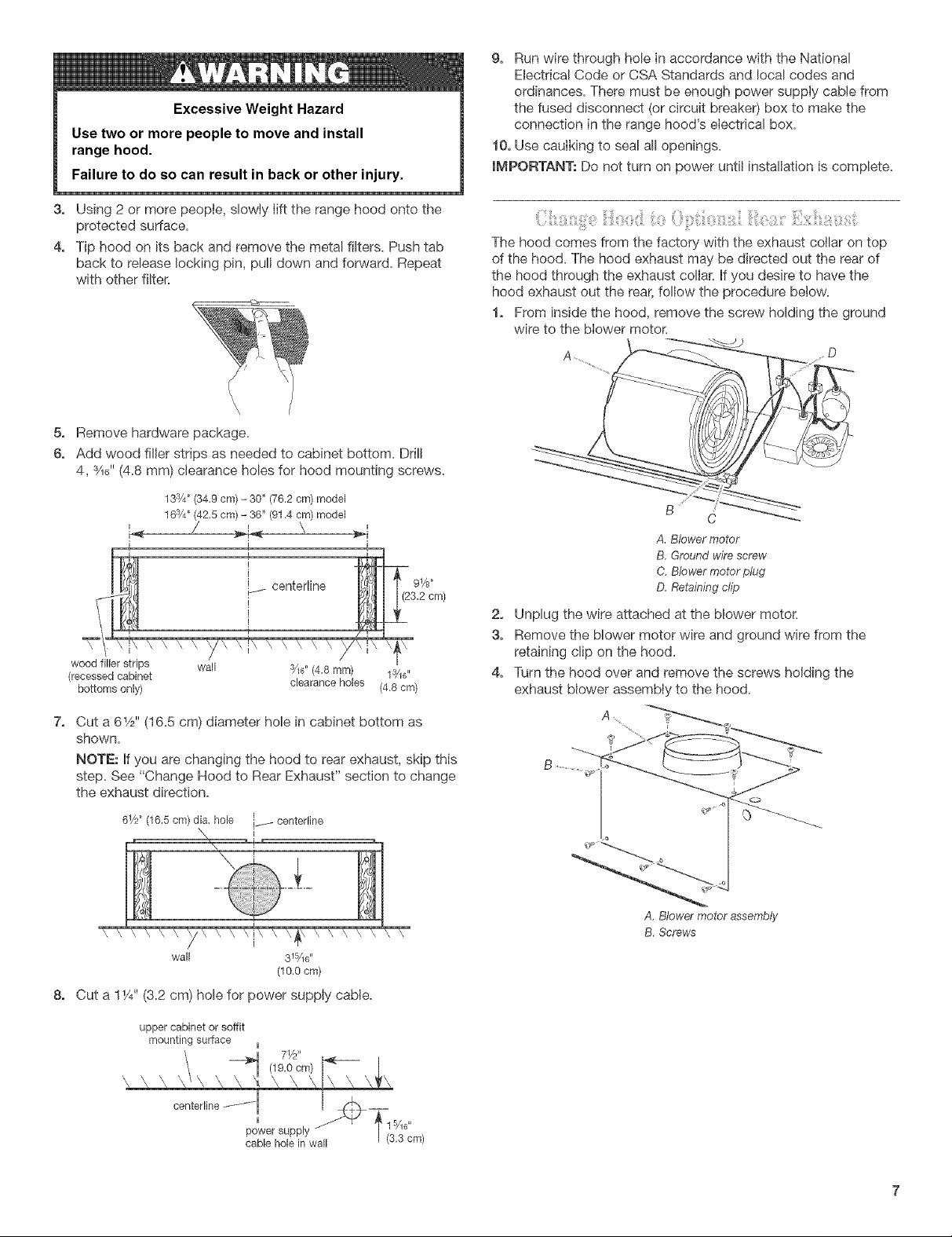
Venting through cabinet top
1. Mark the location where vent cover will be installed in the
cabinet top and cut a 6" (15.2 cm) round vent opening for the
vent cover
IMPORTANT: Do not terminate exhaust into a dead air space
such as an attic or enclosed soffit.
C
A, Vent system D. Ceiling or soffit
B. Vent cover E, Hood
C. Cabinet top
[] For vented installations, it is recommended that the vent
system be installed before hood is installed.
[] Do not cut a joist or stud unless absolutely necessary. If a
joist or stud must be cut, then a supporting frame must be
constructed.
[] Before making cutouts, make sure there is proper clearance
within the ceiling or wall for vent fittings.
[] Check that all the installation parts and the box with filters
have been removed from the shipping carton.
Preparation
1. If possible, disconnect power and/or gas supply and move
freestanding or slide-in range from cabinet opening to
provide easier access to rear wall.
2. Select a flat surface for assembling the hood. Cover that
surface with a protective covering such as a blanket or
cardboard during assembly.
Excessive Weight Hazard
Use two or more people to move and install
range hood.
Failure to do so can result in back or other injury.
3. Using 2 or more people, slowty Iift the range hood onto the
protected surface=
4o Tip hood on its back and remove the metal filters. Push tab
back to release locking pin, pull down and forward. Repeat
with other filter=
5o Remove hardware package.
6o Add wood filler strips as needed to cabinet bottom. Drill
3 H
4, Y_6(4=8mm) clearance holes for hood mounting screws.
9. Run wire through hole in accordance with the National
Electrical Code or CSA Standards and local codes and
ordinances= There must be enough power supply cable from
the fused disconnect (or circuit breaker) box to make the
connection in the range hood's electrical box=
10. Use caulking to seal all openings=
iMPORTANT: Do not turn on power until installation is complete=
The hood comes from the factory with the exhaust collar on top
of the hood. The hood exhaust may be directed out the rear of
the hood through the exhaust collar. If you desire to have the
hood exhaust out the rear, follow the procedure below.
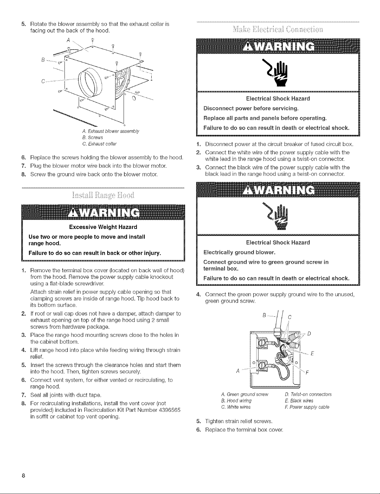
1. From inside the hood, remove the screw holding the ground
wire to the blower motor.
O
13's/4"(34,9 cm) -30" (76.2 cm) model
163/4,,(42,5 cm) -36" (91_4 cm) model
' / _d< \
I
wood filler strips wall s/re" (4,8 ram)
(recessed cabinet 1:_/_"
bottoms only) (4_8 cm)
7,
Cut a 6_/2'' (16.5 cm) diameter hole in cabinet bottom as
shown.
NOTE: If you are changing the hood to rear exhaust, skip this
step. See "Change Hood to Rear Exhaust" section to change
the exhaust direction.
61/2` (16.5 cm) dia, hole i.... centerhne
wall 315/1(;'
8,
Cut a 11/4'' (32 cm) hole for power supply cable.
clearance holes
I
(10.Ocm)
B j
c
A. Blowermotor
B.Groundwirescrew
C.Blowermotorplug
D.Retainingclip
2=
Unplug the wire attached at the blower motor.
3,
Remove the blower motor wire and ground wire from the
retaining clip on the hood.
Turn the hood over and remove the screws holding the
exhaust blower assembly to the hood.
A, Blower motor assembly
B, Screws
upper cabinet or soffit
mounting surface u
centerline ....... ul _1
power supply s/le"
cable hole in wall
Rotate the blower assembly so that the exhaust collar is
5. ii!y}is_ii_igeiil}!30_ii:{:!:rlii:i_i!i! ,iil}g,liiiiiiii_i!_Ci:iOS
facing out the back of the hood,
A, _?
t
I
Electdcam Shock Hazard
Disconnect power before servicing,
Repmace aH parts and panels before operating,
A.Exhaustblowerassembly
Failure to do so can resumt in death or eJectricam shock.
B,Screws
C.Exhaustcollar
1, Disconnect power at the circuit breaker of fused circuit box.
2, Connect the white wire of the power supply cable with the
6, Replace the screws holding the blower assembiy to the hood,
7, Plug the blower motor wire back into the blower motor,
8, Screw the ground wire back onto the blower motor,
white lead in the range hood using a twist-on connector,
3, Connect the black wire of the power suppiy cable with the
black lead in the range hood using a twist-on connector.
Excessive Weight Hazard
Use two or more people to move and install
range hood.
Failure to do so can result in back or other injury.
1, Remove the terminal box cover (located on back wall of hood)
from the hood, Remove the power supply cable knockout
using a flat-blade screwdriver.
Attach strain relief in power supply cable opening so that
clamping screws are inside of range hood. Tip hood back to
its bottom surface.
2, if roof or wall cap does not have a damper, attach damper to
exhaust opening on top of the range hood using 2 small
screws from hardware package.
3, Place the range hood mounting screws close to the holes in
the cabinet bottom,
4, Lift range hood into ptace while feeding wiring through strain
relief.
5. insert the screws through the clearance holes and start them
into the hood. Then, tighten screws securely.
6. Connect vent system, for either vented or recirculating, to
range hood.
7. Seal all joints with duct tape.
8. For recircutating installations, install the vent cover (not
provided) included in Recirculation Kit Part Number 4396565
in soffit or cabinet top vent opening.
Electdcam Shock Hazard
EmectdcaHy ground blower.
Connect ground wire to green ground screw in
terminam box.
Failure to do so can resumt in death or eJectdcam shock.
4, Connect the green power supply ground wire to the unused,
green ground screw.
D
A .........
'F
A. Green ground screw
B, Hood wiring
C, White wires
D. Fwist-onconnectors
E,Blackwires
F.Powersupplycable
5, Tighten strain relief screws.
6, Replace the terminal box cover.
ThishoodcomesstandardwithanArchitect_seriesstainless
steelfronttrimpiece.Toreplacethestandardfronttrimpiecewith
anoptionalpurchasedfronttrimpiece:
1=Reachinsidethefrontofthehoodandlocateahexnut
approximately3"(7.6cm)infrombothoutsideedges.
2=Removethe7mmhexnuts.
A.Hood
B.Hexnut
C. Trimpiece
3= Pull the trim piece straight out.
4= Insert the studs on the back of the new trim piece through the
holes in the front of the hood.
5= Replace the hex nuts and tighten securely.
Removable Interchangeable Front Trim Part Numbers:
30" (76,2 ore} models
Color Series Part Number
White Architect _ 8212462
Black Architect _ 8212463
Biscuit Architect _" 8212461
Stainless Pro Lind ") 8212464
Meteorite Pro Lind _ 8212465
36" (91=4cm) models
i i
Color Series Part Number
White Architect _= 8212467
Black Architect _ 8212468
Biscuit Architect _ 8212466
Stainless Pro Line'_ 8212469
Meteorite Pro Line'_ 8212470
2= Replace metal filter. Place back edge of metal filter into
channel at rear of hood. Push filter up while pushing tab back.
\
\,
When filter is in place, release tab. Locking pin w/I hold filter
Jnplace.
Check operation of the range hood by turning on the power.
2=
The range hood controls are located infront on the underside
of the range hood.
B
A.Controls
B,Filters
3. Move the/ght switch to "1" position. The light should turn on.
4. Move blower switch to "1" position. The blower should
operate.
5. Move the blower speed switch to "1" position for low speed,
"2" position for medium speed or "3" position for high speed.
6. Move blower and light switches to "0" position to turn blower
and light off.
7. Ifthe range hood does not operate, check to see whether a
circuit breaker has tripped or a house fuse has blown.
Disconnect power supply and check that the wiring is correct.
NOTE: To get the most efficient use from your new range hood,
read the "Range Hood Use" section.
:: t
For recirculating instalations only, install the charcoal filters
included in Recirculation Kit Part Number 4396565. Place the
charcoal filter against the blower cover and rotate to the right
(clockwise) to attach to cover. Repeat with other charcoal filter.
A,Filter
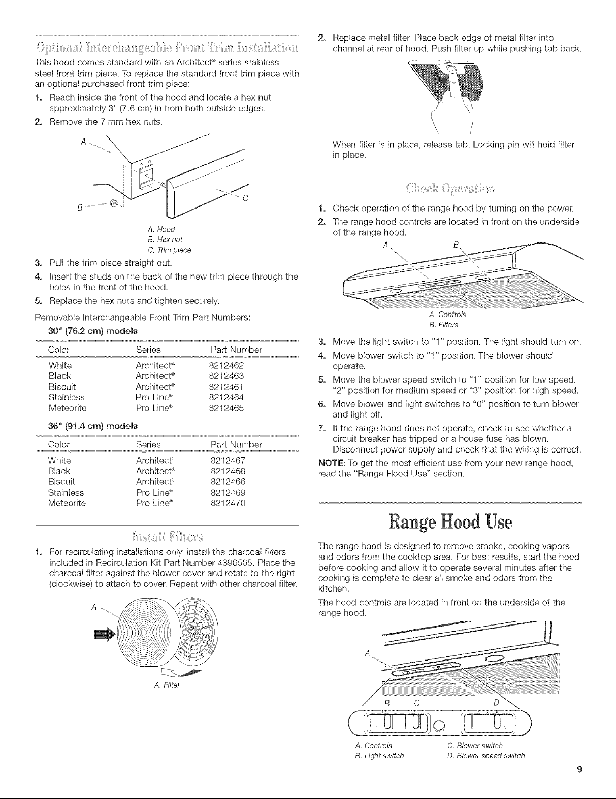
Rangetood Use
The range hood is designed to remove smoke, cooking vapors
and odors from the cooktop area. For best results, start the hood
before cooking and alow it to operate several minutes after the
cooking is complete to clear a/smoke and odors from the
kitchen.
The hood controls are located in front on the underside of the
range hood,
A
C
©
A, Controls C, Blower switch
B. Light switch D. Blower speed switch
 Loading...