


KitchenAid KHTU165RSS1, KHTU105RSS1 Owner’s Manual
I_itchen_kid ®
30" (76.2 CM) AND 36" (91.4 CM) RANGE HOOD
HOTTE D'ASPIRATION DE 30" (76,2 CM)
ET 36" (91,4 CM)
Table of Contents/Table des matieres ............................................................................. 2
IMPORTANT: READ AND SAVE THESE INSTRUCTIONS.
IMPORTANT : LIRE ET CONSERVER CES INSTRUCTIONS.
iMPORTANT:
installer: Leave installation instructions with the homeowner,
Homeowner: Keep installation instructions for future reference,
Save installation instructions for IocaI electrical inspector's use,
iMPORTANT :
Installateur : Remettre Ies instructions d'instalIation au proprietaire,
Proprietaire : Conserver Ies instructions d'instalation pour r_f_rence ulterieure,
Conserver les instructions d'insta/ation pour consultation par Finspecteur local des instalations _lectriques,
9763380
TABLEOF CONTENTS TABLE DES MATIERES
RANGE HOOD SAFETY ................................................................. 2
INSTALLATION REQUIREMENTS ................................................ 3
Tools and Parts ............................................................................ 3
Location Requirements ................................................................ 4
Venting Requirements .................................................................. 4
Electrical Requirements ............................................................... 5
INSTALLATION INSTRUCTIONS .................................................. 6
Venting Options ............................................................................ 6
Prepare Location .......................................................................... 6
Install Range Hood ....................................................................... 7
Make Electrical Connection ......................................................... 8
Install Filters .................................................................................. 8
Check Operation .......................................................................... 8
RANGE HOOD USE ........................................................................ 9
Range Hood Controls .................................................................. 9
RANGE HOOD CARE ..................................................................... 9
Range Hood Lamps ..................................................................... 9
Cleaning ........................................................................................ 9
Accessories ................................................................................ 10
ASSISTANCE OR SERVICE ......................................................... 10
In the U.S.A ................................................................................ 10
In Canada ................................................................................... 10
WAR RANTY .................................................................................. 11
WIRING DIAGRAM ....................................................................... 12
SECURITI :!:DE LA HOTTE D'ASPIRATION ................................ 13
EXIGENCES D'INSTALLATION ................................................... 15
Outillage et pieces ...................................................................... 15
Exigences d'emplacement ......................................................... t 5
Exigences concernant I'evacuation ........................................... 16
Specifications electriques .......................................................... 17
INSTRUCTIONS D'INSTALLATION ............................................. 18
Options disponibles pour le circuit d'evacuation ...................... 18
Preparation de I'emplacement ................................................... 18
Installation de la hotte de cuisiniere ........................................... 19
Raccordement electrique ........................................................... 20
Installation des filtres .................................................................. 20
Contr61e du fonctionnement ...................................................... 20
UTILISATION DE LA HOTTE DE CUlSINIERE ........................... 21
Commandes de la hotte de cuisiniere ....................................... 21
ENTRETIEN DE LA HOTTE DE CUlSINIERE ............................. 21
Lampes de la hotte de cuisiniere ............................................... 21
Nettoyage ................................................................................... 21
Accessoires ................................................................................ 22
ASSISTANCE OU SERVICE ......................................................... 22
GARANTI E ..................................................................................... 23
SCHI:!:MADE CABLAGE ............................................................... 24
RANGE HOOD SAFETY
Your safety and the safety of others are very important.
We have provided many important safety messages in this manual and on your appliance. Always read and obey all safety
messages.
This is the safety alert symbol.
This symbol alerts you to potential hazards that can kill or hurt you and others.
All safety messages will follow the safety alert symbol and either the word "DANGER" or "WARNING."
These words mean:
You can be killed or seriously injured if you don't immediately
follow instructions.
You can be killed or seriously injured if you don't follow
instructions.
All safety messages will tell you what the potential hazard is, tell you how to reduce the chance of injury, and tell you what can
happen if the instructions are not followed.
iMPORTANT SAFETY iNSTRUCTiONS
WARNING: TO REDUCE THE RiSK OF FIRE, ELECTRIC
SHOCK, OR iNJURY TO PERSONS, OBSERVE THE
FOLLOWING:
_, Use this unit only in the manner intended by the
manufacturer, if you have questions, contact the
manufacturer.
_, Before servicing or cleaning the unit, switch the power off at
the service panel disconnecting means to prevent power
from being switched on accidentally. When the service
disconnecting means cannot be locked, securely fasten a
prominent warning device, such as a tag, to the service
panel.
_, installation work and electrical wiring must be done by
qualified person(s) in accordance with alI applicable codes
& standards, including fire-rated construction.
_, Sufficient air is needed for proper combustion and
exhausting of gases through the flue (chimney) of fuel
burning equipment to prevent backdrafting. Foilow the
heating equipment manufacturer's guideline and safety
standards such as those published by the Nationai Fire
Protection Association (NFPA), the American Society for
Heating, Refrigeration and Air Conditioning Engineers
(ASHRAE), and the local code authorities.
_, When cutting or drilling into watI or ceiling; do not damage
electricaI wiring and other utilities.
_, Ducted systems must always be vented outdoors.
CAUTION: For general ventilating use only. Do not use
to exhaust hazardous or explosive materials and vapors.
CAUTION: To reduce risk of fire and to properly exhaust
air, be sure to duct air outside - do not vent exhaust air into
spaces within walls ceilings, attics, crawl spaces, or
garages.
WARNING: TO REDUCE THE RISK OF FIRE, USE ONLY
METAL DUCTWORK.
WARNING: TO REDUCE THE RISK OF A RANGE TOP
GREASE FIRE:
_, Never leave the surface units unattended at high settings.
Boilovers cause smoking and greasy spilIovers that may
ignite. Heat oils slowly on Iow or medium settings.
_, Always turn hood ON when cooking at high heat or when
fiambeing food (i.e. Crepes Suzette, Cherries Jubilee,
Peppercorn Beef Flambe).
_, Clean ventilating fans frequently. Grease should not be
allowed to accumulate on fan or filter.
_, Use proper pan size. Always use cookware appropriate for
the size of the surface element.
WARNING: TO REDUCE THE RISK OF INJURY TO
PERSONS IN THE EVENT OF A RANGE TOP GREASE
FIRE, OBSERVE THE FOLLOWING: _
_, SMOTHER FLAMES with a close fitting lid, cookie sheet, or
other metal tray, then turn off the gas burner or electric
element. BE CAREFUL TO PREVENT BURNS. If the
flames do not go out immediately, EVACUATE AND CALL
THE FIRE DEPARTMENT.
,,, NEVER PICK UP A FLAMING PAN - you may be burned.
_, DO NOT USE WATER, including wet dishcloths or towels
a violent steam explosion will result.
_, Use an extinguisher ONLY if:
- You know you have a class ABC extinguisher, and you
already know how to operate it.
- The fire is small and contained in the area where it
started.
- The fire department is being called.
- You can fight the fire with your back to an exit.
aBased on "Kitchen Fire Safety Tips" published by NFPA.
,,, WARNING: To reduce the risk of fire or electrical shock,
do not use this fan with any solid-state speed control
device.
SAVE THESE iNSTRUCTiONS
INSTALLATION REQUIREMENTS
Gather the required tools and parts before starting installation. • Duct tape
Read and follow the safety instructions provided with any tools • Flat-blade screwdriver
listed here.
Tools needed • Metal snips
• Level • Phillips screwdriver
• Drill
• 11/4"drill bit
• Pencil
• Pliers
• Wire stripper or utility knife
• Tape measure or ruler
• Caulking gun and weatherproof caulking compound
• Saber or keyhole saw
Parts supplied
Check that all parts are included.
• Literature package
• Hardware package (4 screws)
Parts needed
UL listed or CSA approved 1/2"(12.5 ram) strain reliefs (2)
Power supply cable
6" (15.2 cm) round wall or roof cap
6" (15.2 cm) metal vent system
IMPORTANT:Observeallgoverningcodesandordinances.
• Itistheinstaller'sresponsibilitytocomplywithinstallation
clearancesspecifiedonthemodel/serialratingplate.The
model/serialratingplateislocatedinsidetherangehoodon
therearwall.
Rangehoodlocationshouldbeawayfromstrongdraftareas,
suchaswindows,doorsandstrongheatingvents.
Cabinetopeningdimensionsthatareshownmustbeused.
Givendimensionsprovideminimumclearance.Consultyour
cooktop/rangemanufacturerinstallationinstructionsbefore
makinganycutouts.
Groundedelectricaloutletisrequired.See"Electrical
Requirements"section.
Thehoodisfactorysetforventedinstallations.For
recirculatinginstallations,RecirculationKitPartNumber
4396565,includingventcoverand2charcoalfilters,is
availablefromyourdealer.
Allopeningsinceilingandwallwhererangehoodwillbe
installedmustbesealed.
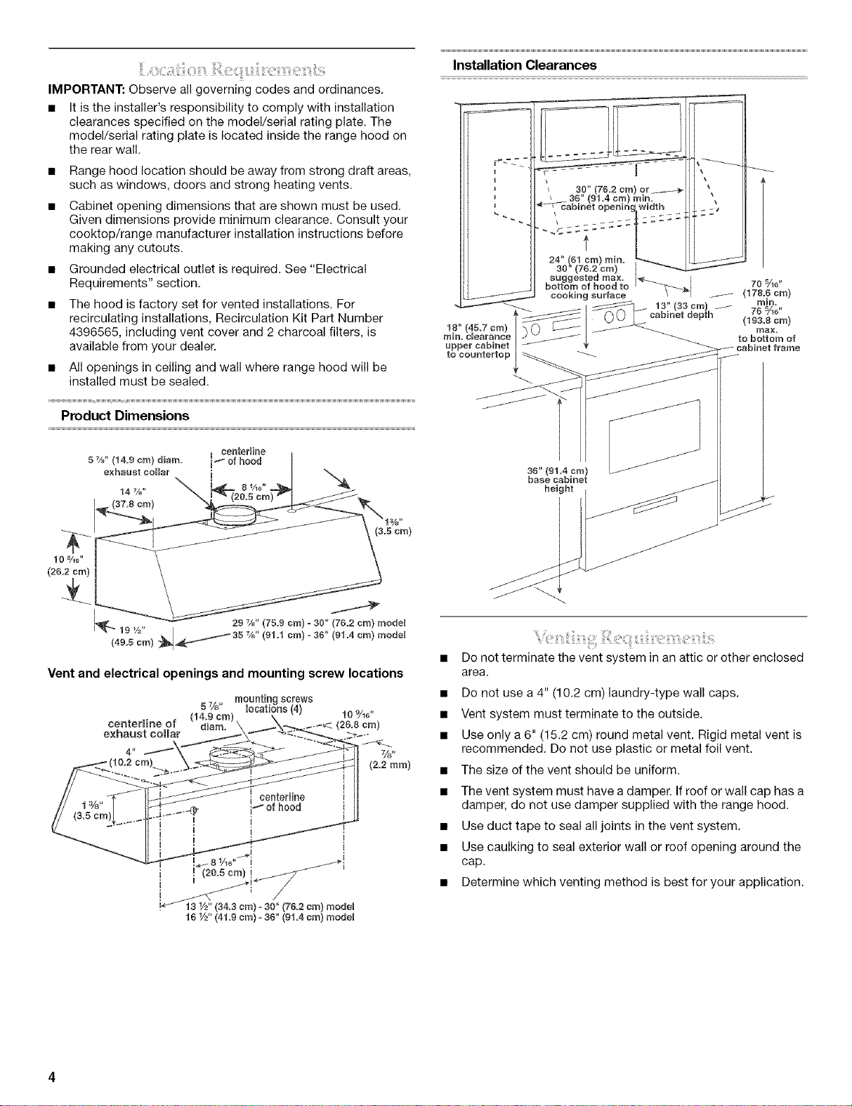
Product Dimensions
Installation Clearances
18" (45.7 sra) |
rain. clearance [
upper cabinet |
to eountertop
f
3_" (91.4 ere)
base cab[aet
height
(3.5 era)
10 %o"
(25.2 era)
19 V=" / 35
(49.5 Cra) __ %_" (91.1 Cra)- 36" (91.4 Cra) raode[
Vent and electrical openings and mounting screw locations
centerHne of d[ara. \ _._,_ (26,8 am)
exhaust collar
4" %,
29 %_" (75.9 sra) = 30" (76=2 era) raode[
mountingscrews
5%" locations(4) 1o9/H'
(14,9 cra)
(2.2 tara)
• Do not terminate the vent system in an attic or other enclosed
area.
• Do not use a 4" (10.2 cm) laundry-type wall caps.
• Vent system must terminate to the outside.
• Use only a 6" (15.2 cm) round metal vent. Rigid metal vent is
recommended. Do not use plastic or metal foil vent.
• The size of the vent should be uniform.
• The vent system must have a damper. If roof or wall cap has a
damper, do not use damper supplied with the range hood.
• Use duct tape to seal all joints in the vent system.
• Use caulking to seal exterior wall or roof opening around the
cap.
• Determine which venting method is best for your application.
For Best Performance:
• Do not install 2 elbows together.
• Use no more than three 90 ° elbows.
• If an elbow is used, install it as far away as possible from the
hood's vent motor exhaust opening.
• Make sure there is a minimum of 24" (61 cm) of straight vent
between the elbows if more than one elbow is used.
The length of vent system and number of elbows should be kept
to a minimum to provide efficient performance.
Cold Weather Installations
An additional backdraft damper should be installed to minimize
backward cold air flow and a nonmetallic thermal installed to
minimize conduction of outside temperatures as part of the vent
system. The damper should be on the cold air side of the thermal
break.
Makeup Air
Local building codes may require the use of makeup air systems
when using ventilation systems with greater than specified CFM
of air movement. The specified CFM varies from locale to locale.
Consult your HVAC professional for specific requirements in your
area.
Venting Methods
This range hood is factory set for vented installations. Vent
system can terminate through either the roof or wall. A
6" (15.2 cm) round vent system must be used. The vent system
length should not exceed 35 ft (10.7 m).
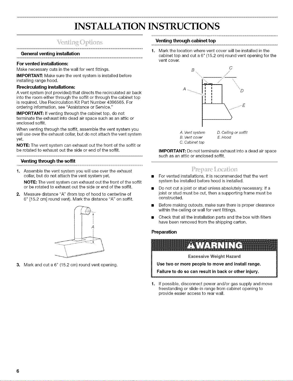
Option 1 - Roof Venting Option 2 - Wall Venting
A. 6" (15.2 crn) round roof A. 6" (15.2 cm) round wall
venting venting
B. Roof cap B. Wall cap
Calculating Vent System Length
To calculate the length of the system you need, add the
equivalent feet (meters) for each vent piece used in the system.
Vent piece 6" (15.2 cm} round
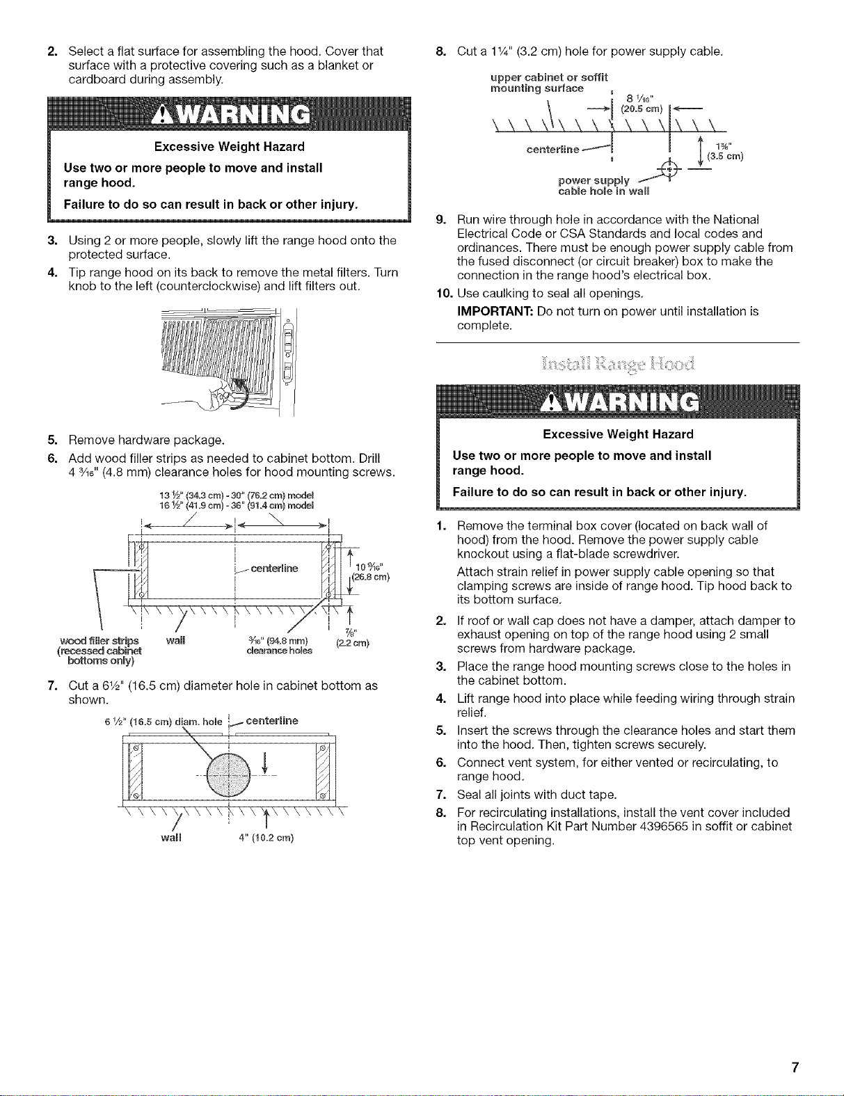
45° elbow 2.5 ft (0.8 m)
90° elbow 5.0 ft (1.5 m)
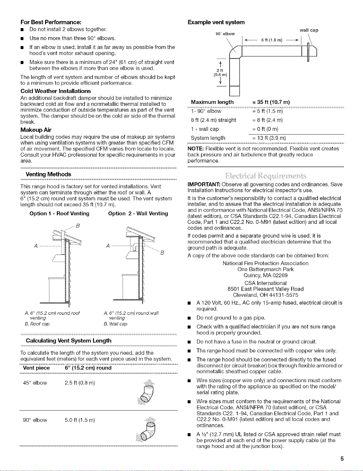
Example vent system
90 ° elbow
Maximum length = 35 ft (10.7 m)
1- 90° elbow = 5 ft (1.5 m)
8 ft (2.4 m) straight = 8 ft (2.4 m)
1 - wall cap = 0 ft (0 m)
System length = 13 ft (3.9 m)
NOTE: Flexible vent is not recommended. Flexible vent creates
back pressure and air turbulence that greatly reduce
performance.
IMPORTANT: Observe all governing codes and ordinances. Save
Installation Instructions for electrical inspector's use.
It is the customer's responsibility to contact a qualified electrical
installer, and to assure that the electrical installation is adequate
and in conformance with National Electrical Code, ANSI/NFPA 70
(latest edition), or CSA Standards C22.1-94, Canadian Electrical
Code, Part 1 and C22.2 No. 0-M91 (latest edition) and all local
codes and ordinances.
If codes permit and a separate ground wire is used, it is
recommended that a qualified electrician determine that the
ground path is adequate.
A copy of the above code standards can be obtained from:
National Fire Protection Association
One Batterymarch Park
Quincy, MA 02269
CSA International
8501 East Pleasant Valley Road
Cleveland, OH 44131-5575
• A 120 Volt, 60 Hz., AC only 15-amp fused, electrical circuit is
required.
• Do not ground to a gas pipe.
• Check with a qualified electrician if you are not sure range
hood is properly grounded.
• Do not have a fuse in the neutral or ground circuit.
• The range hood must be connected with copper wire only.
• The range hood should be connected directly to the fused
disconnect (or circuit breaker) box through flexible armored or
nonmetallic sheathed copper cable.
• Wire sizes (copper wire only) and connections must conform
with the rating of the appliance as specified on the model/
serial rating plate.
Wire sizes must conform to the requirements of the National
Electrical Code, ANSI/NFPA 70 (latest edition), or CSA
Standards C22.1-94, Canadian Electrical Code, Part 1 and
C22.2 No. 0-M91 (latest edition) and all local codes and
ordinances.
• A 1/2"(12.7 mm) UL listed or CSA approved strain relief must
be provided at each end of the power supply cable (at the
range hood and at the junction box).
INSTALLA ON INSTRUCTIONS
Venting through cabinet top
General venting installation
For vented installations:
Make necessary cuts in the wall for vent fittings.
IMPORTANT: Make sure the vent system is installed before
installing range hood.
Rrecirculating installations:
A vent system (not provided) that directs the recirculated air back
into the room either through the soffit or through the cabinet top
is required. Use Recirculation Kit Part Number 4396565. For
ordering information, see "Assistance or Service."
IMPORTANT: If venting through the cabinet top, do not
terminate the exhaust into dead air space such as an attic or
enclosed soffit.
When venting through the soffit, assemble the vent system you
will use over the exhaust collar, but do not attach the vent system
yet.
NOTE: The vent system can exhaust out the front of the soffit or
be rotated to exhaust out the side or end of the soffit.
Venting through the soffit
Assemble the vent system you will use over the exhaust
collar, but do not attach the vent system yet.
NOTE: The vent system can exhaust out the front of the soffit
or be rotated to exhaust out the side or end of the soffit.
2. Measure distance "A" (from top of hood to centerline of
6" [15.2 cm] round vent). Mark the distance "A" on soffit.
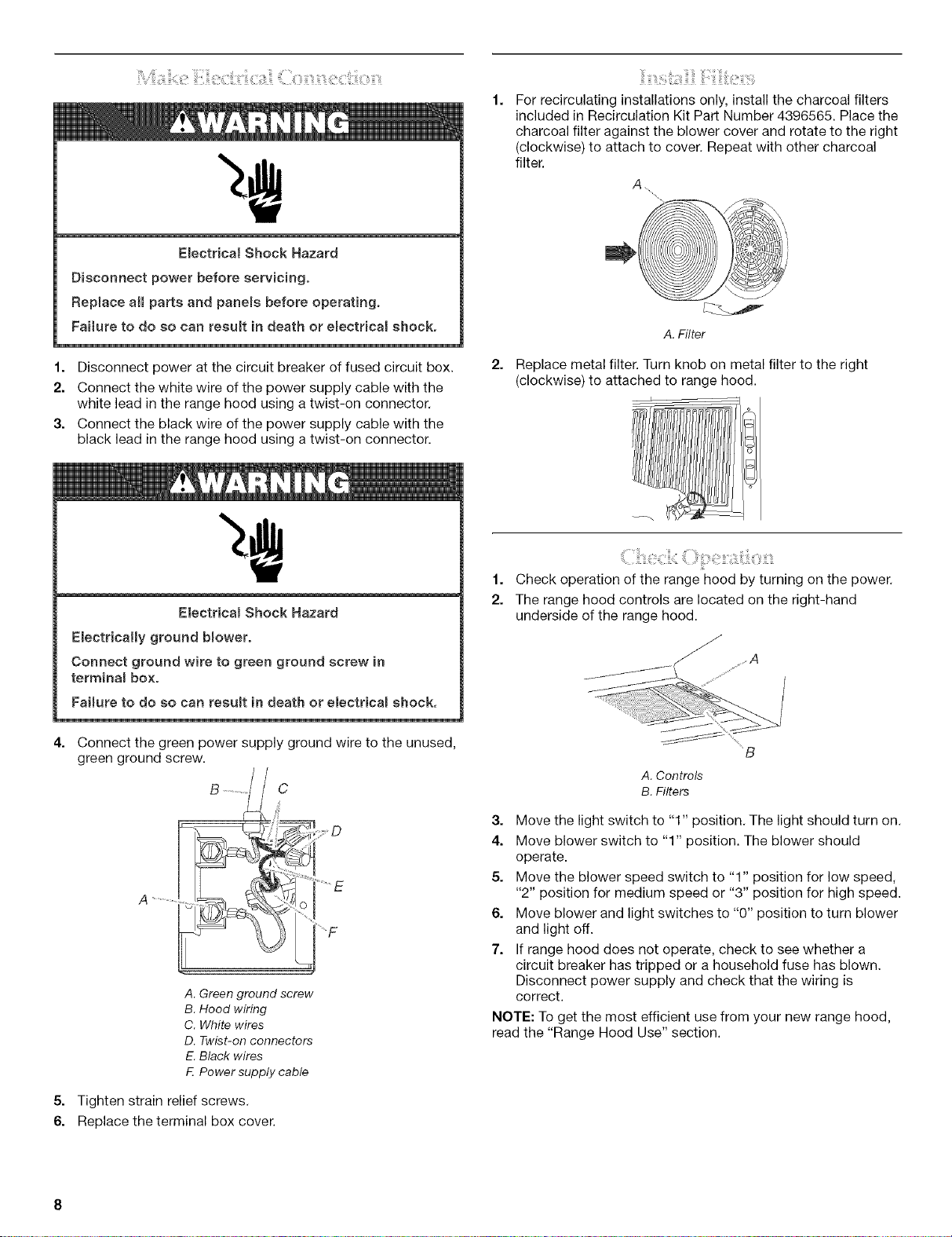
1. Mark the location where vent cover will be installed in the
cabinet top and cut a 6" (15.2 cm) round vent opening for the
vent cover.
B
"%,,,, ,Si /
A. Vent system D. Ceiling or soffit
B. Vent cover E.Hood
C. Cabinet top
IMPORTANT: Do not terminate exhaust into a dead air space
such as an attic or enclosed soffit.
For vented installations, it is recommended that the vent
system be installed before hood is installed.
Do not cut ajoist or stud unless absolutely necessary. If a
joist or stud must be cut, then a supporting frame must be
constructed.
Before making cutouts, make sure there is proper clearance
within the ceiling or wall for vent fittings.
Check that all the installation parts and the box with filters
have been removed from the shipping carton.
C
3. Mark and cut a 6" (15.2 cm) round vent opening.
Preparation
iii!,
Excessive
Use two or more people to move and install range.
Failure to do so can result in back or other injury.
1. If possible, disconnect power and/or gas supply and move
freestanding or slide-in range from cabinet opening to
provide easier access to rear wall.
2. Selectaflatsurfaceforassemblingthehood.Coverthat
surfacewithaprotectivecoveringsuchasablanketor
cardboardduringassembly.
8. Cut a 11/4"(3.2 cm) hole for power supply cable.
upper cabinet or soffit
mounting surface _
\ _1 (20=5 cra)I<'_
8 Ae"
Excessive Weight Hazard
Use two or more people to move and install
range hood.
Failure to do so can result in back or other injury.
3. Using 2 or more people, slowly lift the range hood onto the
protected surface.
4. Tip range hood on its back to remove the metal filters. Turn
knob to the left (counterclockwise) and lift filters out.
5. Remove hardware package.
6. Add wood filler strips as needed to cabinet bottom. Drill
4 3/16"(4.8 mm) clearance holes for hood mounting screws.
131_,, (34.3 cra)= 30" (76.2 cra) raodet
161/2" (41.9 cra)= 36" (91.4 cra) raodeJ
!< 71< \
_.,. [I L__centermirle I_ ".
4/ I _26=8cra)
/ t
I ; / ' / i 7/s,,
wood filler strips
(recessed cabinet
bottoms only)
7. Cut a 61/2'' (16.5 cm) diameter hole in cabinet bottom as
shown.
6 1/2" (16.5 cm) diara= hole I._ centerHne
Wall 3Ae" (94=8 ram} (2.2 cra}
wall 4" (10.2 era)
cUeaH_nceholes
ceo,er,,.ef'l I t
' x% ,(3 ora,
power supply _ T
cabRehole in wall
g. Run wire through hole in accordance with the National
Electrical Code or CSA Standards and local codes and
ordinances. There must be enough power supply cable from
the fused disconnect (or circuit breaker) box to make the
connection in the range hood's electrical box.
10. Use caulking to seal all openings.
IMPORTANT: Do not turn on power until installation is
complete.
Excessive Weight Hazard
Use two or more people to move and install
range hood.
Failure to do so can result in back or other injury.
Remove the terminal box cover (located on back wall of
hood) from the hood. Remove the power supply cable
knockout using a flat-blade screwdriver.
Attach strain relief in power supply cable opening so that
clamping screws are inside of range hood. Tip hood back to
its bottom surface.
2. If roof or wall cap does not have a damper, attach damper to
exhaust opening on top of the range hood using 2 small
screws from hardware package.
3. Place the range hood mounting screws close to the holes in
the cabinet bottom.
4. Lift range hood into place while feeding wiring through strain
relief.
5. Insert the screws through the clearance holes and start them
into the hood. Then, tighten screws securely.
6. Connect vent system, for either vented or recirculating, to
range hood.
7. Seal all joints with duct tape.
8. For recirculating installations, install the vent cover included
in Recirculation Kit Part Number 4396565 in soffit or cabinet
top vent opening.
Emectrica_ShockHazard
Disconnectpowerbeforeservicing.
Replaceaimpartsandpanemsbefore operating.
Failure to do so can resuJt in death or emectr}cal shock.
E
1. Disconnect power at the circuit breaker of fused circuit box.
2. Connect the white wire of the power supply cable with the
white lead in the range hood using a twist-on connector.
3. Connect the black wire of the power supply cable with the
black lead in the range hood using a twist-on connector.
For recirculating installations only, install the charcoal filters
included in Recirculation Kit Part Number 4396565. Place the
charcoal filter against the blower cover and rotate to the right
(clockwise) to attach to cover. Repeat with other charcoal
filter.
A
A.Filter
Replace metal filter. Turn knob on metal filter to the right
(clockwise) to attached to range hood.
Electricam Shock Hazard
EmectricaHy ground bmower.
Connect ground wire to green ground screw in
terminam box.
Faimure to do so can resumt in death or e_ectricam shock.
4. Connect the green power supply ground wire to the unused,
green ground screw.
A ...................
A. Green ground screw
B. Hood wiring
C. White wires
D. Twist-on connectors
E. Black wires
F Power supply cable
1.
Check operation of the range hood by turning on the power.
2.
The range hood controls are located on the right-hand
underside of the range hood.
"B
A. Controls
B. Filters
3. Move the light switch to "1" position. The light should turn on.
4. Move blower switch to "1" position. The blower should
operate.
5. Move the blower speed switch to "1" position for low speed,
"2" position for medium speed or "3" position for high speed.
6. Move blower and light switches to "0" position to turn blower
and light off.
7. If range hood does not operate, check to see whether a
circuit breaker has tripped or a household fuse has blown.
Disconnect power supply and check that the wiring is
correct.
NOTE: To get the most efficient use from your new range hood,
read the "Range Hood Use" section.
5. Tighten strain relief screws.
6. Replace the terminal box cover.