

KitchenAid KHTU160KSS1, KHTU160KWH1, KHTU165RSS0, KHTU160KBL1, KHTU100KBL1 Installation Guide
...
iMPORTANT:
Quick Reference
Read and save
these instructions.
iMPORTANT:
Installer: Leave Installation instructions with
the homeowner.
Homeowner: Keep Installation Instructions for
future reference.
Save Installation Instructions for local electrical
inspector'suse.
4329589/9763392
Table of Contents:
Pages
[] Before you start
[] Electrical requirements
[] Vent system requirements
[] Product dimensions
[_=[] Installation steps
[] Wiring diagram
[]-[] Use and Care Information
[] Warranty
[_= [] Requesting Assistance
or Service
Your safety and the safety of
others are very important.
We haveprovided many important
safety messagesin this manual and
on your appliance. Always readand
obey all safety messages.
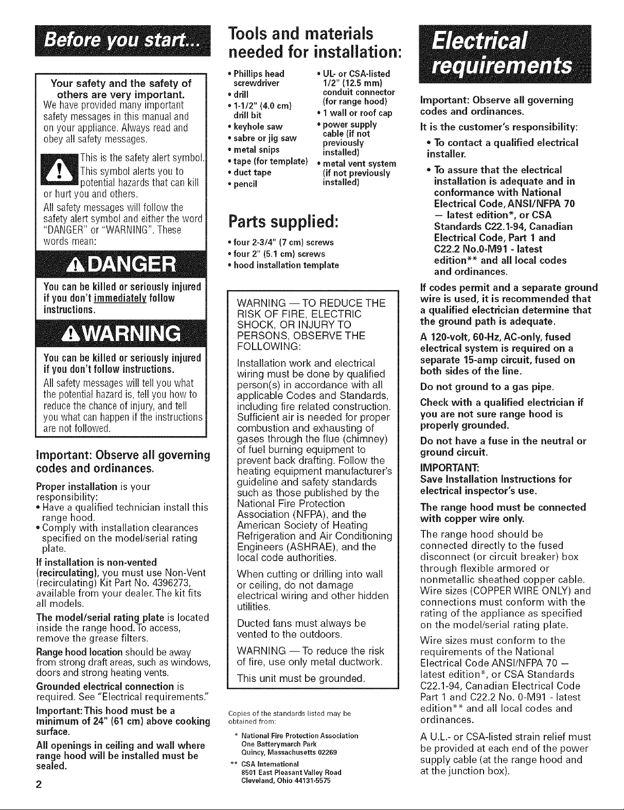
This is the safety alertsymbol.
This symbol alertsyou to
potential hazardsthat can kill
or hurt you and others.
All safety messageswill follow the
safety alert symbol and eitherthe word
"DANGER"or "WARNING".These
words mean:
Youcan be killed or seriously injured
if you don't follow instructions.
All safety messageswill tell you what
the potential hazard is,tell you howto
reducethe chanceof injury,and tell
you what can happenif the instructions
are not followed.
Important: Observe all governing
codes and ordinances.
Proper installation is your
responsibility:
• Have a qualified technician installthis
range hood.
• Comply with installation clearances
specified on the model/serial rating
plate.
if installation is non-vented
(recirculating}, you must use Non-Vent
(recirculating) Kit Part No. 4396273,
available from your dealer.The kit fits
all models.
The model/serial rating plate is located
inside the range hood.To access,
remove the grease filters.
Rangehoodlocation should be away
from strong draft areas, such as windows,
doors and strong heating vents.
Grounded electrical connection is
required. See "Electrical requirements;'
Important: This hood must be a
minimum of 24" (61 cm} above cooking
surface.
All openings in ceiling and wall where
range hood wUl be installed must be
sealed.
Tools and materials
needed for installation:
Phillips head • UL-or CSA-listed
screwdriver 1/2" (12.5 ram}
• drill conduit connector
• 1-1/2" (4.0 cm) (for range hood)
drill bit • 1wall or roof cap
• keyhole saw • power supply
• sabre or jig saw previously
• metal snips installed)
• tape (for template) • metal vent system
• duct tape (if not previously
• pencil installed}
cable (if not
Parts supplied:
• four 2-3/4" (7 cm) screws
• four 2" (5.1 cm) screws
hood installation template
WARNING -- TO REDUCE THE
RISK OF FIRE, ELECTRIC
SHOCK, OR INJURY TO
PERSONS, OBSERVE THE
FOLLOWING:
Installation work and electrical
wiring must be done by qualified
person(s) in accordance with all
applicable Codes and Standards,
including fire related construction.
Sufficient air is needed for proper
combustion and exhausting of
gases through the flue (chimney)
of fuel burning equipment to
prevent back drafting. Follow the
heating equipment manufacturer's
guideline and safety standards
such as those published by the
National Fire Protection
Association (NFPA), and the
American Society of Heating
Refrigeration and Air Conditioning
Engineers (ASHRAE), and the
local code authorities.
When cutting or drilling into wall
or ceiling, do not damage
electrical wiring and other hidden
utilities.
Ducted fans must always be
vented to the outdoors.
WARNING --To reduce the risk
of fire, use only metal ductwork.
This unit must be grounded.
Copies of the standards listed may be
obtained from:
* National Fire Protection Association
One Batteryrnarch Park
Quincy, Massachusetts 02269
** CSA International
8501 East Pleasant Valley Road
Cleveland, Ohio 44131-5575
important: Observe all governing
codes and ordinances.
it is the customer's responsibility:
* To contact a qualified electrical
installer.
, To assure that the electrical
installation is adequate and in
conformance with National
Electrical Code, ANSI/NFPA 70
- latest edition*, or CSA
Standards C22.1-94, Canadian
Electrical Code, Part 1 and
C22.2 No.0-M91 - latest
edition** and all local codes
and ordinances.
if codes permit and a separate ground
wire is used, it is recommended that
a qualified electrician determine that
the ground path is adequate.
A 120-volt, 60-Hz, AC-only, fused
electrical system is required on a
separate 15-amp circuit, fused on
both sides of the line.
Do not ground to a gas pipe.
Check with a qualified electrician if
you are not sure range hood is
properly grounded.
Do not have a fuse in the neutral or
ground circuit.
iMPORTANT:
Save Installation instructions for
electrical inspector's use.
The range hood must be connected
with copper wire only.
The range hood should be
connected directly to the fused
disconnect (or circuit breaker) box
through flexible armored or
nonmetallic sheathed copper cable.
Wire sizes (COPPERWIRE ONLY) and
connections must conform with the
rating of the appliance as specified
on the model/serial rating plate.
Wire sizes must conform to the
requirements of the National
Electrical Code ANSl/NFPA 70 -
latest edition*, or CSA Standards
C22.1-94, Canadian Electrical Code
Part 1 and C22.2 No. 0-M91 - latest
edition** and all local codes and
ordinances.
A U.L.- or CSA-listed strain relief must
be provided at each end of the power
supply cable (at the range hood and
at the junction box).
For vented models:
Do not terminate the vent system
in an attic or other enclosed area.
Do not use 4" (10.2 cm) laundry-
type wall caps.
Use metal vent only. Rigid metal
vent is recommended. Do not use
plastic or metal foil vent.
Fle×ible vent is not
recommended. Flexible vent
creates back pressure that greatly
reduces the hood's performance.
• The size of the vent should be
uniform.
• Use no more than three 90°
elbows.
Make sure there is a minimum
of 24" (61 cm) of straight vent
between the elbows if more
than one elbow is used.
Do Not install two elbows
together.
The length of vent system and
number of elbows should be
kept to a minimum to provide
efficient performance.
The vent system must have a
damper. If roof or wall cap has
a damper, Do Not use damper
supplied with the range hood.
Use duct tape to seal all joints
in the vent system.
• Use caulking to seal exterior wall
or roof opening around the cap.
Note: It is recommended that the
vent system be installed before
installing the hood.
3-1/4" x
(8.3 cmx 25 cm
vent through
the wall
wall
cap
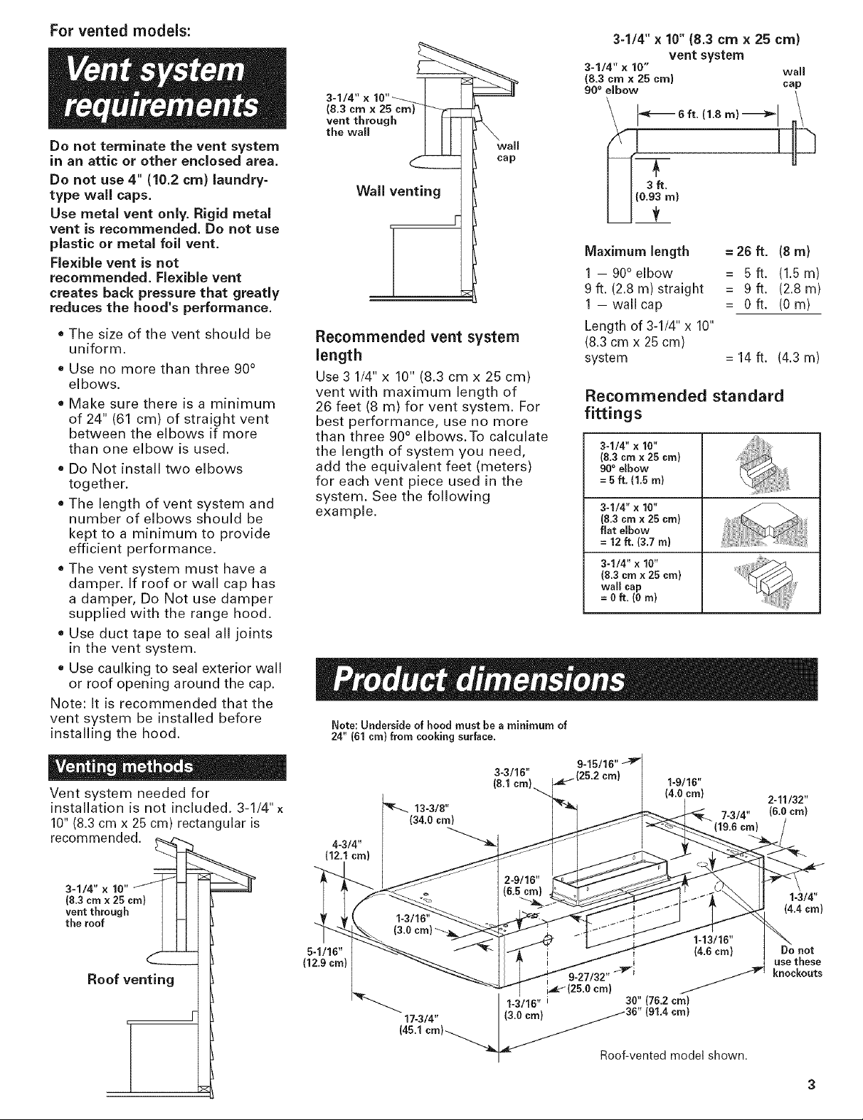
Wall venting
Recommended vent system
length
Use 3 1/4" x 10" (8.3 cm x 25 cm)
vent with maximum length of
26 feet (8 m) for vent system. For
best performance, use no more
than three 90° elbows.To calculate
the length of system you need,
add the equivalent feet (meters)
for each vent piece used in the
system. See the following
example.
Note: Underside of hood must be a minimum of
24" (61 cm} from cooking surface.
3-1/4" x 10" (8.3 cmx 25 cm}
vent system
3-1/4" x 10" wall
(8.3 crn x 25 cm)
90° elbow cap
_- 6ft. (1.8m)-_ll _
Maximum length = 26 ft. (8 m)
1 -90 ° elbow = 5ft, (1.5m)
9 ft. (2.8 m) straight = 9 ft. (2.8 m)
1 -wallcap = 0ft. (0m)
Length of 3-1/4" x 10"
(8.3 cmx 25 cm)
system = 14 ft. (4.3 m)
Recommended standard
fittings
3-1/4" x 16"
(8.3 cmx 25 cm)
90° elbow
= 5 ft. (1.5 m)
3-1/4" x 10"
(8.3 cmx 25 cm)
flat elbow
= 12 ft. (3,7 m)
3-1/4" x 10"
(8.3 cmx 25 cm}
wall cap
= Oft.(O m)
Vent system needed for
installation is not included. 3-1/4" x
10"(8.3 cmx 25 cm) rectangular is
recommendecL _
vent through I I I
the roof
Roof venting
3-3116"
(8.1 cm} 1-9/16"
(4.0 cm) 2-11/32"
13-3/8" 7-3/4" (6.0 cm}
4-3/4"
(12.1 cm}
1-3/4"
(4.4 cm}
5-1/16" Do not
(12.9 cm) _ use these
I 1-3/16" 3811(76.2 cm)
17-3/4" (3.0 cm} _36
9-27/32" _"i knockouts
cm}
191.4cm)
(45.1cm, 1
Roof-ventedmodelshown.
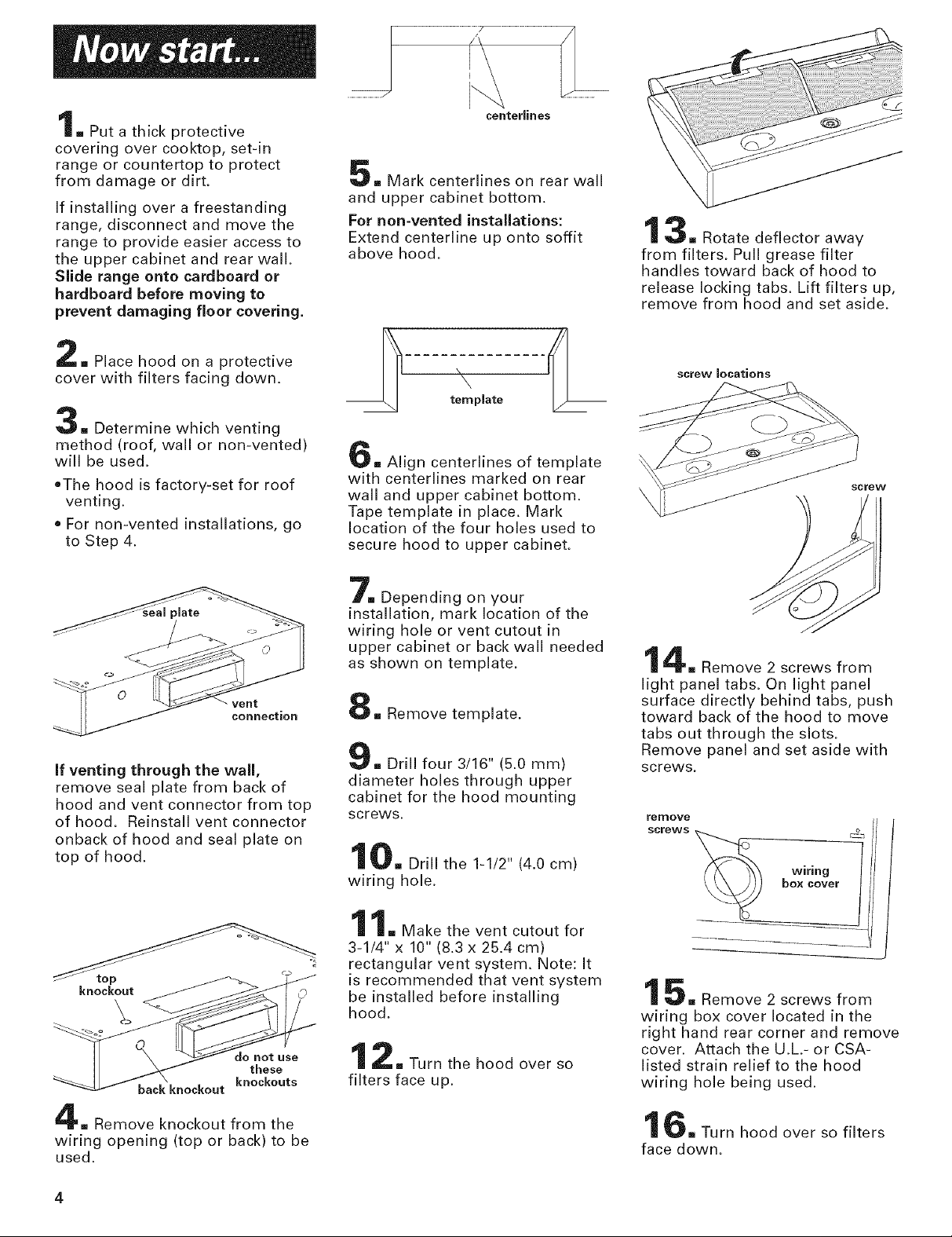
,.Putathickprotective
coveringovercooktop,set-in
rangeorcountertopto protect
fromdamageordirt.
Ifinstallingoverafreestanding
range,disconnectandmovethe
rangeto provideeasieraccessto
theuppercabinetandrearwall.
Sliderangeonto cardboard or
hardboard before moving to
prevent damaging floor covering.
centerlines
= Mark centerlines on rear wall
and upper cabinet bottom.
For non-vented installations:
Extend centerline up onto soffit
above hood.
3= Rotate deflector away
from filters. Pull grease filter
handles toward back of hood to
release locking tabs. Lift filters up,
remove from hood and set aside.
= Place hood on a protective
cover with filters facing down.
3[] Determine which venting
method (roof, wall or non-vented)
will be used.
oThe hood is factory-set for roof
venting.
For non-vented installations, go
to Step 4.
if venting through the wall,
remove seal plate from back of
hood and vent connector from top
of hood. Reinstall vent connector
onback of hood and seal plate on
top of hood.
= Align centerlines of template
with centerlines marked on rear
wall and upper cabinet bottom.
Tape template in place. Mark
location of the four holes used to
secure hood to upper cabinet.
7= Depending on your
installation, mark location of the
wiring hole or vent cutout in
upper cabinet or back wall needed
as shown on template.
m Remove template.
= Drill four 3/16" (5.0 mm)
diameter holes through upper
cabinet for the hood mounting
screws.
10= Drill the 1-1/2" (4.0 cm)
wiring hole.
screw locations
screw
4= Remove 2 screws from
light panel tabs. On light panel
surface directly behind tabs, push
toward back of the hood to move
tabs out through the slots.
Remove panel and set aside with
screws.
remove
screws _ _
wiring
boxcover/
knockout
;o
not use
these
back knockout
= Remove knockout from the
wiring opening (top or back) to be
used.
knockouts
1[] Make the vent cutout for
3-1/4" x 10" (8.3 x 25.4 cm)
rectangular vent system. Note: It
is recommended that vent system
be installed before installing
hood.
2= Turn the hood over so
filters face up.
5= Remove 2 screws from
wiring box cover located in the
right hand rear corner and remove
cover. Attach the U.L.- or CSA-
listed strain relief to the hood
wiring hole being used.
6_ Turn hood over so filters
face down.
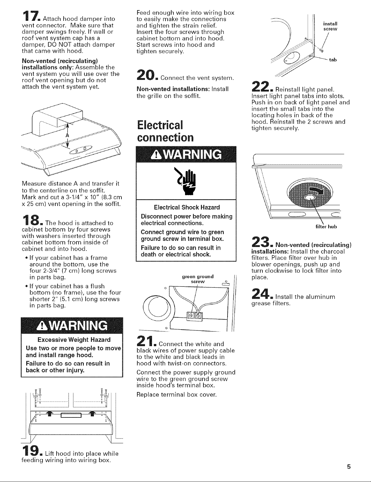
7= Attach hood damper into
vent connector. Make sure that
damper swings freely. If wall or
roof vent system cap has a
damper, DO NOT attach damper
that came with hood.
Non-vented (recirculating)
installations only: Assemble the
vent system you will use over the
roof vent opening but do not
attach the vent system yet.
Measure distance A and transfer it
to the centerline on the soffit.
Mark and cut a 3-1/4" x 10" (8.3 cm
x 25 cm) vent opening in the soffit.
8[] The hood is attached to
cabinet bottom by four screws
with washers inserted through
cabinet bottom from inside of
cabinet and into hood.
• If your cabinet has a frame
around the bottom, use the
four 2-3/4" (7 cm) long screws
in parts bag.
• If your cabinet has a flush
bottom (no frame), use the four
shorter 2" (5.1 cm) long screws
in parts bag.
Feed enough wire into wiring box
to easily make the connections
and tighten the strain relief.
Insert the four screws through
cabinet bottom and into hood.
Start screws into hood and
tighten securely.
[_m Connect the vent system.
Non-vented installations: Install
the grille on the soffit.
Electrical
connection
Electrical Shock Hazard
Disconnect power before making
electrical connections.
Connect ground wire to green
ground screw in terminal box.
Failure to do so can result in
death or electrical shock.
green ground
screw £_
install
screw
/
2[] Reinstall light panel.
Insert light panel tabs into slots.
Push in on back of light panel and
insert the small tabs into the
locating holes in back of the
hood. Reinstall the 2 screws and
tighten securely.
filter hub
3 [] Non-vented (recirculating)
installations: Install the charcoal
filters. Place filter over hub in
blower openings, push up and
turn clockwise to lock filter into
place.
4= Install the aluminum
grease filters.
Excessive Weight Hazard
Use two or more people to move
and install range hood.
Failure to do so can result in
back or other injury.
- / \ --
1 9[] Lift hood into place while
feeding wiring into wiring box.
[] Connect the white and
black wires of power supply cable
to the white and black leads in
hood with twist-on connectors.
Connect the power supply ground
wire to the green ground screw
inside hood's terminal box.
Replace terminal box cover.
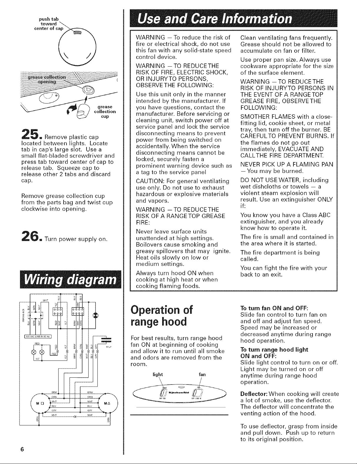
push tab
toward
center of c_
_=_ Remove plastic cap
located between lights. Locate
tab in cap's large slot. Usea
small flat-bladed screwdriver and
press tab toward center of cap to
release tab. Squeeze cap to
release other 2 tabs and discard
cap.
Remove grease collection cup
from the parts bag and twist cup
clockwise into opening.
_m Turn power supply on.
WARNING -- To reduce the risk of
fire or electrical shock, do not use
this fan with any solid-state speed
control device.
WARNING -- TO REDUCETHE
RISK OF FIRE, ELECTRIC SHOCK,
OR INJURYTO PERSONS,
OBSERVE THE FOLLOWING:
Use this unit only in the manner
intended by the manufacturer. If
you have questions, contact the
manufacturer. Before servicing or
cleaning unit, switch power off at
service panel and lock the service
disconnecting means to prevent
power from being switched on
accidentally. When the service
disconnecting means cannot be
locked, securely fasten a
prominent warning device such as
a tag to the service panel
CAUTION: For general ventilating
use only. Do not use to exhaust
hazardous or explosive materials
and vapors.
WARNING -- TO REDUCETHE
RISK OF A RANGETOP GREASE
FIRE:
Never leave surface units
unattended at high settings.
Boilovers cause smoking and
greasy spillovers that may ignite.
Heat oils slowly on low or
medium settings.
Always turn hood ON when
cooking at high heat or when
I
cooking flaming foods.
Clean ventilating fans frequently.
Grease should not be allowed to
accumulate on fan or filter.
Use proper pan size. Always use
cookware appropriate for the size
of the surface element.
WARNING -- TO REDUCE THE
RISK OF INJURYTO PERSONS IN
THE EVENT OF A RANGETOP
GREASE FIRE, OBSERVE THE
FOLLOWING:
SMOTHER FLAMES with a close-
fitting lid, cookie sheet, or metal
tray, then turn off the burner. BE
CAREFULTO PREVENT BURNS. If
the flames do not go out
immediately, EVACUATE AND
CALLTHE FIRE DEPARTMENT.
NEVER PICK UP A FLAMING PAN
--You may be burned.
DO NOT USE WATER, including
wet dishcloths or towels -- a
violent steam explosion will
result. Use an extinguisher ONLY
if:
You know you have a Class ABC
extinguisher, and you already
know how to operate it.
The fire is small and contained in
the area where it is started.
The fire department is being
called.
You can fight the fire with your
back to an exit.
Operation of
range hood
For best results, turn range hood
fan ON at beginning of cooking
and allow it to run until all smoke
and odors are removed from the
room.
light fan
To turn fan ON and OFF:
Slide fan control to turn fan on
and off and adjust fan speed.
Speed may be increased or
decreased anytime during range
hood operation.
To turn range hood light
ON and OFF:
Slide light control to turn on or off.
Light may be turned on or off
anytime during range hood
operation.
Deflector: When cooking will create
a lot of smoke, use the deflector.
The deflector will concentrate the
venting action of the hood.
To use deflector, grasp from inside
and pull down. Push up to return
to its original position.
 Loading...