

KitchenAid KHSU265WBA, KHSU205WBA Installation Instructions
30" (76.2 CM) AND 36" (91.4 CM)
SLIDE-OUT VENT HOOD
Installation Instructions and Use & Care Guide
HOTTE D'ASPIRATION AVEC MODULE DE
COMMANDE EXTRACTIBLE DE 30" (76,2 CM)
ET 36" (91,4 CM)
Instructions d’installation et Guide d’utilisation et d’entretien
Table of Contents/Table des matières.............................................................................2
IMPORTANT: READ AND SAVE THESE INSTRUCTIONS.
FOR RESIDENTIAL USE ONLY.
IMPORTANT : LIRE ET CONSERVER CES INSTRUCTIONS.
POUR UTILISATION RÉSIDENTIELLE UNIQUEMENT.
W10267109C

TABLE OF CONTENTS
TABLE DES MATIÈRES
RANGE HOOD SAFETY .................................................................3
INSTALLATION REQUIREMENTS................................................5
Tools and Parts ............................................................................5
Location Requirements................................................................5
Venting Requirements..................................................................6
Electrical Requirements ...............................................................8
INSTALLATION INSTRUCTIONS..................................................8
Prepare Location..........................................................................8
Install Range Hood.....................................................................11
Electrical Connection .................................................................12
Connect the Vent System ..........................................................12
Optional Gray Vinyl Trim ............................................................13
Optional Front Trim Kits.............................................................13
RANGE HOOD USE......................................................................14
RANGE HOOD CARE...................................................................15
Cleaning......................................................................................15
Replacing the Bulb.....................................................................15
WIRING DIAGRAM .......................................................................16
ASSISTANCE OR SERVICE.........................................................17
In the U.S.A. ...............................................................................17
In Canada ...................................................................................17
Accessories................................................................................17
WARRANTY ..................................................................................18
SÉCURITÉ DE LA HOTTE D’ASPIRATION ................................19
EXIGENCES D’INSTALLATION...................................................21
Outils et composants .................................................................21
Exigences d'emplacement.........................................................21
Exigences concernant l’évacuation ...........................................22
Spécifications électriques ..........................................................24
INSTRUCTIONS D'INSTALLATION.............................................24
Préparation de l'emplacement...................................................24
Installation de la hotte ................................................................28
Raccordement électrique...........................................................28
Raccordement du circuit d'évacuation......................................29
Garniture en vinyle gris (facultative) ...........................................29
Ensembles de garniture avant (facultatifs).................................30
UTILISATION DE LA HOTTE .......................................................30
ENTRETIEN DE LA HOTTE..........................................................31
Nettoyage ...................................................................................31
Remplacement de l'ampoule .....................................................32
SCHÉMAS DE CÂBLAGE ...........................................................33
ASSISTANCE OU SERVICE.........................................................34
Au Canada..................................................................................34
Accessoires ................................................................................34
GARANTIE.....................................................................................35
2
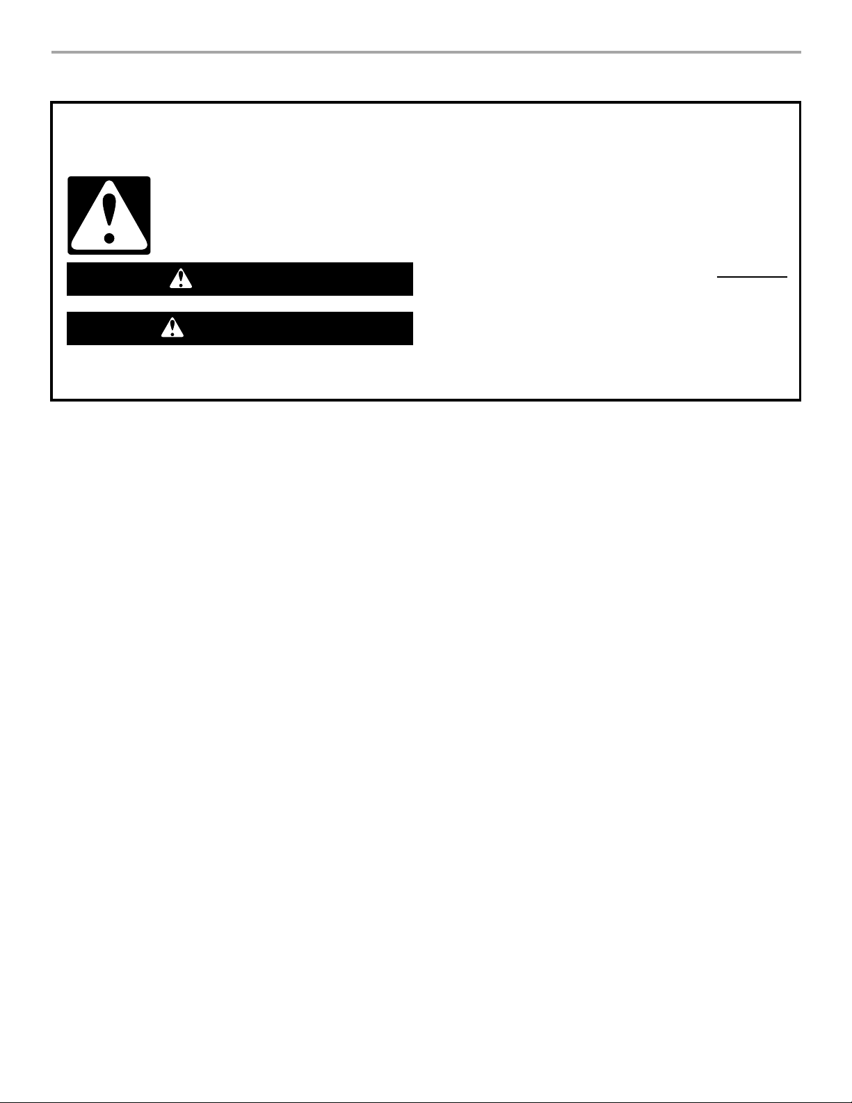
RANGE HOOD SAFETY
Your safety and the safety of others are very important.
We have provided many important safety messages in this manual and on your appliance. Always read and obey all safety
messages.
This is the safety alert symbol.
This symbol alerts you to potential hazards that can kill or hurt you and others.
All safety messages will follow the safety alert symbol and either the word “DANGER” or “WARNING.”
These words mean:
You can be killed or seriously injured if you don't immediately
DANGER
WARNING
All safety messages will tell you what the potential hazard is, tell you how to reduce the chance of injury, and tell you what can
happen if the instructions are not followed.
follow instructions.
can be killed or seriously injured if you don't
You
instructions.
follow
3

IMPORTANT SAFETY INSTRUCTIONS
WARNING: TO REDUCE THE RISK OF FIRE, ELECTRIC
SHOCK, OR INJURY TO PERSONS, OBSERVE THE
FOLLOWING:
■ Use this unit only in the manner intended by the
manufacturer. If you have questions, contact the
manufacturer.
■ Before servicing or cleaning the unit, switch power off at
service panel and lock the service disconnecting means to
prevent power from being switched on accidentally. When
the service disconnecting means cannot be locked,
securely fasten a prominent warning device, such as a tag,
to the service panel.
■ Installation work and electrical wiring must be done by
qualified person(s) in accordance with all applicable codes
and standards, including fire-rated construction.
■ Sufficient air is needed for proper combustion and
exhausting of gases through the flue (chimney) of fuel
burning equipment to prevent backdrafting. Follow the
heating equipment manufacturer's guideline and safety
standards such as those published by the National Fire
Protection Association (NFPA), the American Society for
Heating, Refrigeration and Air Conditioning Engineers
(ASHRAE), and the local code authorities.
■ When cutting or drilling into wall or ceiling; do not damage
electrical wiring and other utilities.
■ Ducted fans must always be vented outdoors.
CAUTION: For general ventilating use only. Do not use
to exhaust hazardous or explosive materials and vapors.
CAUTION: To reduce risk of fire and to properly exhaust
air, be sure to duct air outside - do not vent exhaust air into
spaces within walls or ceilings, attics or into crawl spaces,
or garages.
WARNING: TO REDUCE THE RISK OF FIRE, USE ONLY
METAL DUCTWORK.
WARNING: TO REDUCE THE RISK OF A RANGE TOP
GREASE FIRE:
■ Never leave surface units unattended at high settings.
Boilovers cause smoking and greasy spillovers that may
ignite. Heat oils slowly on low or medium settings.
■ Always turn hood ON when cooking at high heat or when
flambeing food (i.e. Crepes Suzette, Cherries Jubilee,
Peppercorn Beef Flambé).
■ Clean ventilating fans frequently. Grease should not be
allowed to accumulate on fan or filter.
■ Use proper pan size. Always use cookware appropriate for
the size of the surface element.
WARNING: TO REDUCE THE RISK OF INJURY TO
PERSONS IN THE EVENT OF A RANGE TOP GREASE
FIRE, OBSERVE THE FOLLOWING:
■ SMOTHER FLAMES with a close fitting lid, cookie sheet, or
metal tray, then turn off the burner. BE CAREFUL TO
PREVENT BURNS. If the flames do not go out
immediately, EVACUATE AND CALL THE FIRE
DEPARTMENT.
■ NEVER PICK UP A FLAMING PAN - you may be burned.
■ DO NOT USE WATER, including wet dishcloths or towels -
a violent steam explosion will result.
■ Use an extinguisher ONLY if:
– You know you have a class ABC extinguisher, and you
already know how to operate it.
– The fire is small and contained in the area where it
started.
– The fire department is being called.
– You can fight the fire with your back to an exit.
a
Based on "Kitchen Fire Safety Tips" published by NFPA.
a
READ AND SAVE THESE INSTRUCTIONS
4

INSTALLATION REQUIREMENTS
Tools and Parts
Gather the required tools and parts before starting installation.
Read and follow the instructions provided with any tools listed
here.
Tools ne e d e d
■ Level
■ Drill
■ 1¹⁄₄" drill bit
■ ³⁄₈" (8 mm) nut driver or ratchet
■ Pencil
■ Pliers
■ Wire stripper or utility knife
■ Tape measure or ruler
■ Caulking gun and weatherproof caulking compound
■ Phillips screwdriver
■ Flat-blade screwdriver
■ Saber or keyhole saw
■ Vent clamps
■ Metal snips
Parts needed
■ Home power supply cable
■ Tw o ¹⁄₂" (12.7 mm) UL listed or CSA approved strain reliefs
For vented installations, you will also needed:
■ 1 wall or roof cap
■ Metal vent system
For non-vented (recirculating) installations, you will also
need:
■ Recirculation Kit Part Number 4396565. See “Assistance or
Service” section to order.
Optional parts needed:
■ Wood filler strips for cabinets with recessed bottoms. Length
and thickness determined by recess dimensions. See
“Prepare Location” section.
■ Two, 1" x 1" x 5" (25.4 x 25.4 x 127 mm) wood pieces for
cabinet floor. See “Prepare Location” section.
■ Four, 1¹⁄₄" (31.8 mm) wood screws
Parts supplied
Remove parts from packages. Check that all parts are included.
■ 2 screws (used for mounting the vent grate)
■ Damper
■ Plastic cover (used for customized front trim)
■ Hardware package
■ Vent grate (for non-vented/recirculating installations)
■ Front trim - White (installed), Black, and Brushed Aluminum
■ Gray vinyl strip (used for bottom of cabinet, rear trim and 3
mounting screws)
Location Requirements
IMPORTANT: Observe all governing codes and ordinances.
Have a qualified technician install the range hood. It is the
installer’s responsibility to comply with installation clearances
specified on the model/serial rating plate. The model/serial rating
plate is located behind the left filter on the rear wall of the range
hood.
Range hood location should be away from strong draft areas,
such as windows, doors, and strong heating vents.
Cabinet opening dimensions that are shown must be used. Given
dimensions provide minimum clearance. Consult your cooktop/
range manufacturer installation instructions before making any
cutouts.
Grounded electrical outlet is required. See “Electrical
Requirements” section.
The range hood is factory set for vented installations through the
roof or wall. For non-vented (recirculating) installations see “NonVented (recirculating) Installation Through the Soffit/Cabinet” in
the “Prepare Location” section. Recirculation Kit Part Number
4396565 is available from your dealer or an authorized parts
distributor.
All openings in ceiling and wall where range hood will be installed
must be sealed.
For Mobile Home Installations
The installation of this range hood must conform to the
Manufactured Home Construction Safety Standards, Title 24
CFR, Part 328 (formerly the Federal Standard for Mobile Home
Construction and Safety, title 24, HUD, Part 280) or when such
standard is not applicable, the standard for Manufactured Home
Installation 1982 (Manufactured Home Sites, Communities and
Setups) ANSI A225.1/NFPA 501A*, or latest edition, or with local
codes.
5
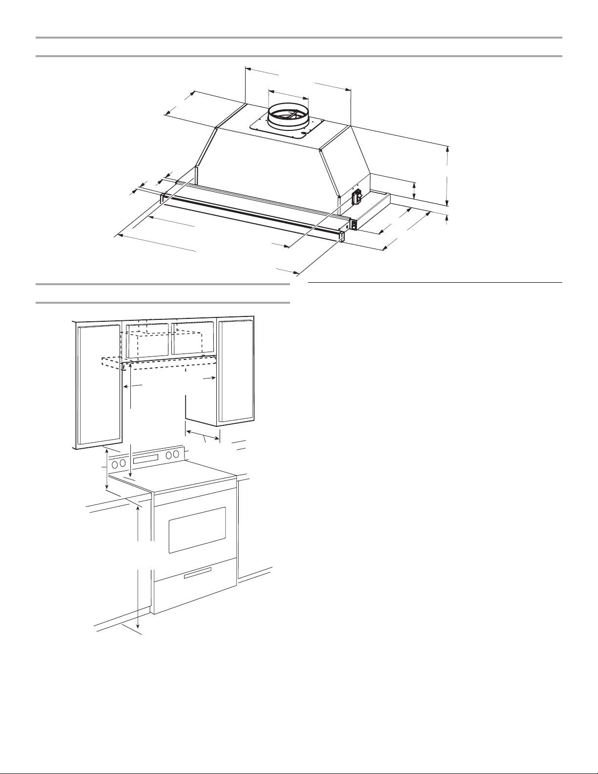
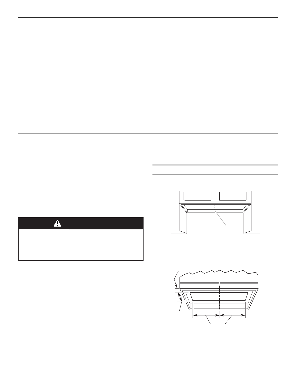
Product Dimensions
17³⁄₈" (44.1 cm) - 30" (76.2 cm) model
23³⁄₈" (59.4 cm) - 36" (91.4 cm) model
6" (15.2 cm)
9¾" (24.8 cm)
¾" (1.9 cm)
Cabinet Dimensions
15" (38.1 cm)
min. clearance
upper cabinet
to countertop
36" (91.4 cm)
base cabinet
height
⁵⁄₈" (1.6 cm)
25¼" (64.1 cm) - 30" (76.2 cm) model
31¼" (79.4 cm) - 36" (91.4 cm) model
29⁷⁄₈" (75.9 cm) - 30" (76.2 cm) model
35⁷⁄₈" (91.1 cm) - 36" (91.4 cm) model
30" (76.2 cm) or
36" (91.4 cm) min.
cabinet opening width
24" (61 cm) min.
30" (76.2 cm)
suggested max.
bottom of cabinet
to cooking surface
13" (33 cm)
cabinet depth
10" (25.4 cm)
3" (7.6 cm)
1⁹⁄₁₆" (4.0 cm)
11" (27.9 cm)
18" (45.7 cm) with screen extended
Venting Requirements
(vented models only)
■ Vent system must terminate to the outside, except for non-
vented (recirculating) installations.
■ Do not terminate the vent system in an attic or other enclosed
area.
■ Do not use a 4" (10.2 cm) laundry-type wall caps.
■ Use a metal vent only. A rigid metal vent is recommended.
Plastic or metal foil vent is not recommended.
■ The length of vent system and number of elbows should be
kept to a minimum to provide efficient performance.
For the most efficient and quiet operation:
■ Use no more than three 90° elbows.
■ Make sure there is a minimum of 24" (61.0 cm) of straight
vent between the elbows if more than 1 elbow is used.
■ Do not install 2 elbows together.
■ The vent system must have a damper. If the roof or wall cap
has a damper, do not use the damper supplied with the range
hood.
■ Use clamps to seal all joints in the vent system.
■ Use caulking to seal exterior wall or roof opening around the
cap.
■ The size of the vent should be uniform.
Cold weather installations
An additional back draft damper should be installed to minimize
backward cold air flow and a thermal break should be installed to
minimize conduction of outside temperatures as part of the vent
system. The damper should be on the cold air side of the thermal
break.
The break should be as close as possible to where the vent
system enters the heated portion of the house.
Makeup air
Local building codes may require the use of makeup air systems
when using ventilation systems with greater than specified CFM
of air movement. The specified CFM varies from locale to locale.
Consult your HVAC professional for specific requirements in your
area.
6
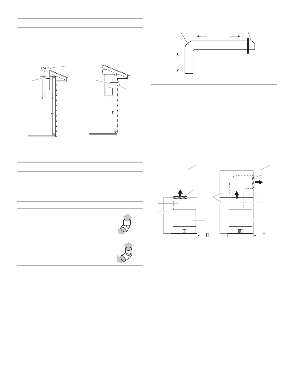
Venting Methods
B
B
This range hood is factory set for venting through the roof or
through the wall.
The vent system needed for installation is not included.
A 6" (15.2 cm) round vent system is recommended.
Roof Venting Wall Venting
Example vent system - 6" (15.2 cm)
90˚ elbow
6 ft (1.8 m)
3 ft
(0.93 m)
Wall cap
A
A. 6" (15.2 cm) vent through
the roof
B. Roof cap
A
A. 6" (15.2 cm) vent through
the wall
B. Wall cap
Calculate Vent System Length
The recommended vent system is 6" (15.2 cm) round vent with a
maximum length of 35 ft (10.7 m). For the best performance, use
no more than three 90° elbows.
To calculate the length of the system, add the equivalent feet
(meters) for each of the vent pieces used in the system.
Vent Piece 6" (15.2 cm)
45° elbow 2.5 ft
(0.8 m)
Maximum Length = 35 ft (10.7 m)
1 - 90° elbow = 5 ft (1.5 m)
1 - wall cap = 0 ft (0 m)
9 ft (2.8 m) straight = 9 ft (2.8 m)
System length = 14 ft (4.3 m)
Non-Vented (recirculating) Installations Through the Soffit/
Cabinet
If it is not possible to vent cooking fumes and vapors to the
outside, the range hood can be used in the non-vented
(recirculating) version, using charcoal filters. Recirculation Kit Part
Number 4396565 is available from the dealer or an authorized
parts distributor. Damper installation is not required.
A
B
F
D
F
E
A
B
C
D
E
90° elbow 5.0 ft
(1.5 m)
A. Ceiling
B. Vent cover
C. Soffit
D. 6" (15.2 cm) vent
E. Range hood
F. C a bi n e t
7
Electrical Requirements
Observe all governing codes and ordinances.
Ensure that the electrical installation is adequate and in
conformance with National Electrical Code, ANSI/NFPA 70 (latest
edition), or CSA Standards C22.1-94, Canadian Electrical Code,
Part 1 and C22.2 No. 0-M91 (latest edition) and all local codes
and ordinances.
If codes permit and a separate ground wire is used, it is
recommended that a qualified electrician determine that the
ground path is adequate.
A copy of the above code standards can be obtained from:
National Fire Protection Association
One Batterymarch Park
Quincy, MA 02269
CSA International
8501 East Pleasant Valley Road
Cleveland, OH 44131-5575
■ A 120 volt, 60 Hz., AC only, 15-amp, fused electrical circuit is
required.
INSTALLATION INSTRUCTIONS
Prepare Location
■ It is recommended that the vent system be installed before
the range hood is installed.
■ Before making cutouts, make sure there is proper clearance
within the ceiling or wall for vent fittings.
1. Disconnect power.
2. Determine which venting method to use: roof, wall, or non-
vented.
3. Select a flat surface for assembling the range hood. Place
covering over that surface.
■ If the house has aluminum wiring, follow the procedure
below:
1. Connect a section of solid copper wire to the pigtail
leads.
2. Connect the aluminum wiring to the added section of
copper wire using special connectors and/or tools
designed and UL listed for joining copper to aluminum.
Follow the electrical connector manufacturer's recommended
procedure. Aluminum/copper connection must conform with
local codes and industry accepted wiring practices.
■ Wire sizes and connections must conform with the rating of
the appliance as specified on the model/serial rating plate.
The model/serial plate is located behind the filter on the rear
wall of the range hood.
■ Wire sizes must conform to the requirements of the National
Electrical Code, ANSI/NFPA 70 (latest edition), or CSA
Standards C22. 1-94, Canadian Electrical Code, Part 1 and
C22.2 No. 0-M91 (latest edition) and all local codes and
ordinances.
Range Hood Cabinet Cutout
1. Determine and clearly mark a centerline on the underside of
the cabinet.
WARNING
Excessive Weight Hazard
Use two or more people to move and install
range hood.
Failure to do so can result in back or other injury.
4. Using 2 or more people, lift range hood onto covered surface.
A
A. Centerline
2. Measure and mark lines as shown for your size of range
hood. Use a saber saw or keyhole saw to cut an opening
through the underside of the cabinet.
1
³⁄₈"
(3.5 cm)
9¹³
⁄₁₆"
(24.9 cm)
30" (76.2 cm) hood - 12⁵
36" (91.4 cm) hood - 15
⁄₈"
(32.0 cm)
⁵⁄₈"
(39.7 cm)
The finished cutout size will be:
30" (76.2 cm) range hood - 9¹³⁄₁₆" x 25¼" (24.9 cm x 64.1 cm)
36" (91.4 cm) range hood - 9¹³⁄₁₆" x 31¼" (24.9 cm x 79.3 cm)
8
3. If the cabinet bottom is recessed above a support frame,
wood filler strips need to be installed on the right and left
sides of the cutout to provide sides of clearance for the
sliding screen. Wood filler strips should be flush with or
recessed ¹⁄₁₆" to ¹⁄₈" (1.6 mm to 3.2 mm) from the bottom of
the support frame.
A
A. Wood filler strips
4. Complete cabinet preparation following the instructions for
your type of installation.
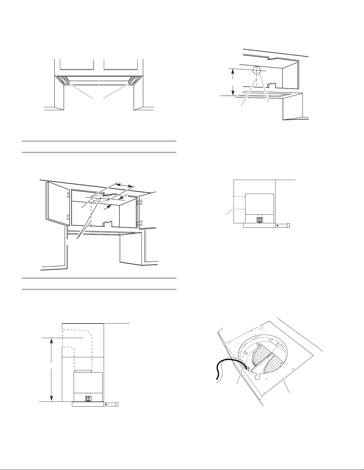
Venting Outside Through the Roof
Measure and mark the lines as shown. Use a saber saw or
keyhole saw to cut a round opening for the vent.
"
6¼
(15.9 cm)
Transfer measurement A to the cabinet back wall. Measure
from the underside of the cabinet or wood filler strips, if used.
Mark the cutout as shown. Use a saber saw or keyhole saw
to cut a round opening for the vent.
A
B
A. Measurement A
B. Centerline
C. 6¼" (15.9 cm) round cutout
C
Change Hood to Optional Rear Exhaust
The hood comes from the factory with the exhaust collar on top
of the hood. The hood exhaust may be directed out the rear of
the hood through the exhaust collar.
Cutout
Centerline
4¹⁄₈"
(10.5 cm)
Venting Outside Through the Wall
Assemble the vent that you will use over the vent opening. Do
not attach the vent at this time. Measure from the top of the
screen housing to the horizontal centerline of the vent
opening (A). Remove the vent.
A
A
A. Rear exhaust
If you desire to have the hood exhaust out the rear, follow the
procedure below.
a.) Place the range hood on its back.
b.) Remove metal filters. See “Range Hood Care” section.
c.) Cut wire tie from wire bundle.
d.) Set the range hood back up to the upright position.
e.) Hold the blower motor to keep it from dropping while
removing the 4 screws holding the exhaust blower to the
range hood. Gently lower blower motor down.
f.) Remove the power supply cable and grommet from the
panel.
A. Measurement A
A
B
A. Power supply cord and grommet
B. Blower mounting panel
g.) Remove the 12 screws from the blower mounting panel
and lift off the panel.
9
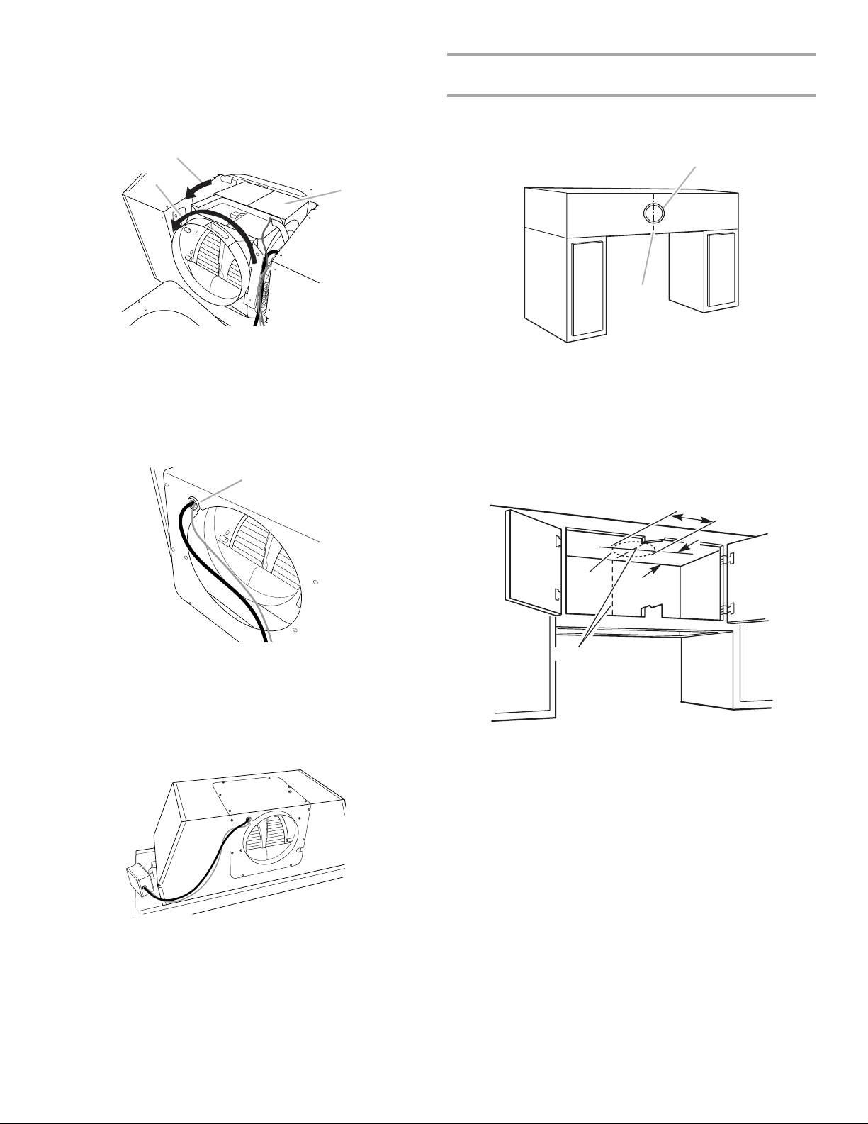
h.) Pull out on the blower motor and rotate it 90° so that the
C
exhaust outlet is pointing out the back. Then rotate the
blower motor around its exhaust axis 180° so the flat side
of the blower motor is pointed up.
NOTE: This is the only way the blower motor will fit
properly in the opening.
B
A
Non-Vented (recirculating) Installation Through the
Soffit/Cabinet
Measure and mark a round vent opening in the soffit using
the method shown for venting through the wall. Measure and
mark the centerline on the soffit above the range hood area.
A
B
A. Rotate 90°
B. Rotate 180°
C. Flat side of blower motor
i.) Check that the wiring is properly positioned.
j.) Place the power supply cable and grommet through the
center of the outlet hole opening in the mounting panel
and reposition the grommet into its mounting notch.
A
A. Grommet/mounting notch
k.) Place the blower mounting panel over the exhaust outlet
and mount it onto the hood housing with the 12 mounting
screws. Tighten the screws.
l.) Pull the blower motor out through the opening in the
blower mounting panel and fasten with the 4 blower
mounting screws.
A. Vent cover
B. Centerline
Use the vent cover included with the range hood or other vent
cover as a template to outline an opening for the vent. Use a
saber saw or keyhole saw to cut a round opening for the vent
system.
The range hood can be vented inside through the top of the
cabinet.
"
6¼
(15.9 cm)
Cutout
Centerline
4¹⁄₈"
(10.5 cm)
For non-vented (recirculating) installations, charcoal filters are
necessary. See the “Range Hood Care” section for
instructions on installing charcoal filters.
The Recirculation Kit Part Number 4396565 must be used.
5. Install the vent system according to the method needed. Use
caulking to seal the exterior wall or roof opening.
6. Run the wiring through the wall or cabinet according to the
national Electrical Code and all local codes and ordinances.
Use caulking to seal around wire opening.
10
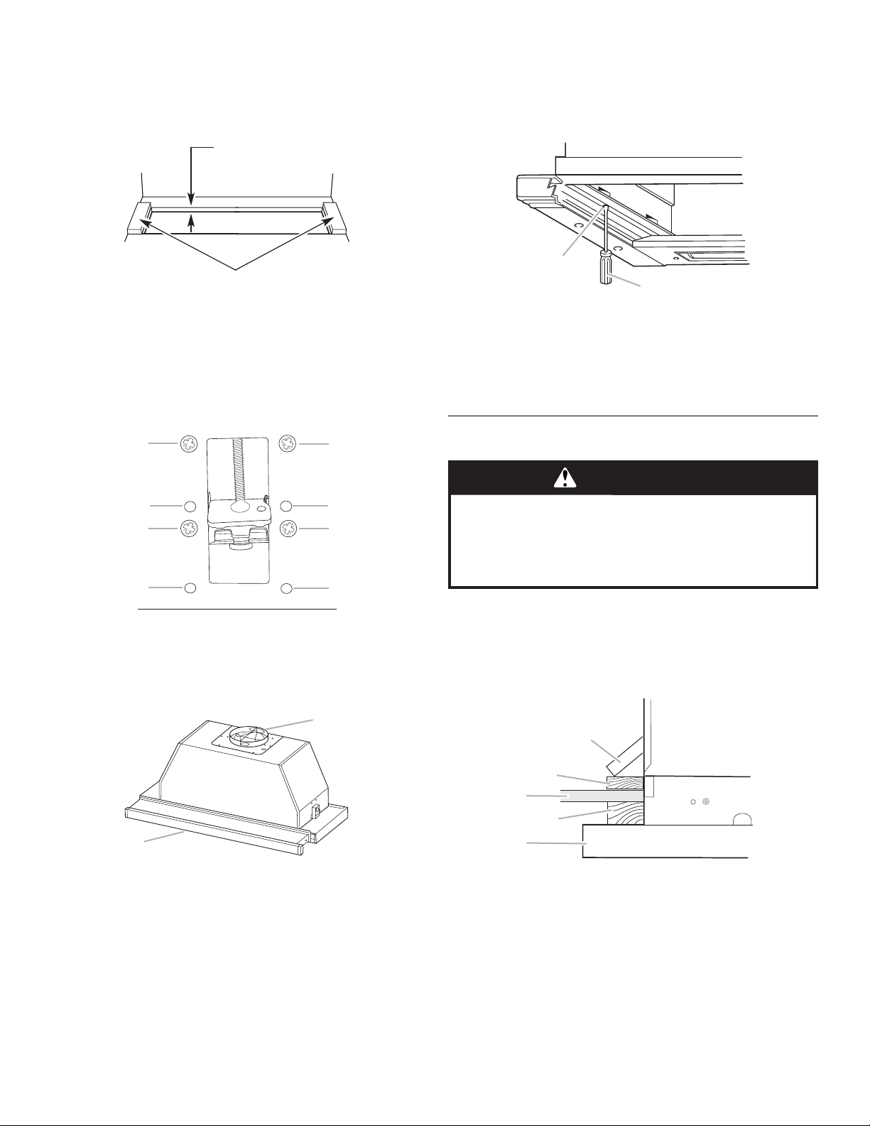
7. Measure the thickness of the cabinet floor, including the filler
A
B
A
B
strips, if used. If the thickness is less than ⁵⁄₈" (15.9 mm),
install wood filler strips that are a minimum length of
5" (12.7 cm) onto the cabinet floor. The mounting bracket
adjusts from ⁵⁄₈" (15.9 mm) to 2¹⁄₈" (54.0 mm) for the wood
filler strips.
A
B
A. Less than ⁵⁄₈" (15.9 mm)
B. Wood fillers (thickness as required)
8. The spring loaded brackets are factory set to accommodate a
thickness between 1³⁄₁₆" (3.0 cm) and 2¼" (5.7 cm). If your
cabinet bottom is less than 1³⁄₁₆" (3.0 cm) thick, the spring
loaded brackets can be removed and repositioned down from
the top setting (A), to the bottom setting (B), by removing the
4 Phillips screws.
10. Place the range hood on its back side on a covered surface.
a) Slide the range hood screen forward.
b) Remove the metal grease filters. See “Range Hood Care”
section.
11. Screw the mounting brackets up to the top position
A
B
A. Mounting bracket screw
B. Flat-blade screwdriver
NOTE: For some non-vented (recirculating) installations it
may be easier to attach the vent system to the range hood
before lifting the range hood into its final location. Seal the
connection with clamps.
A
B
A
B
A. Top setting - factory installed
B. Bottom setting
9. Place the round damper into the vent opening of the range
hood and press down. If the roof cap or wall cap has a
damper, do not attach the damper to the range hood.
A
B
Install Range Hood
WARNING
Excessive Weight Hazard
Use two or more people to move and install
range hood.
Failure to do so can result in back or other injury.
1. Using 2 or more people, lift the range hood into its final
position. (The wiring and terminal box are to be on top of the
range hood.)
2. Check that the mounting brackets overlap the cabinet bottom
or wood filler strips.
3. Center the range hood.
A
B
C
D
E
A. Damper
B. Range hood screen
A. Mounting bracket
B. Optional wood filler strip
C. Cabinet bottom
D. Optional wood filler strip for recessed cabinet
E. Slide-out range hood
11
 Loading...