

KitchenAid KHMS2050S Guide
PRODUCT MODEL NUMBERS
VENTING REQUIREMENTS
Electrical Requirements:
Required:
●
A 120 volt, 60 Hz, AC only, 15- or 20-amp electrical supply with a fuse or
circuit breaker.
Recommended:
●
A time-delay fuse or time-delay circuit breaker.
●
A separate circuit serving only this microwave oven.
Microwave Hood Combination
Because Whirlpool Corporation policy includes a continuous commitment to improve
our products, we reserve the right to change materials and specifications without notice.
Dimensions are for planning purposes only. For complete details, see Installation
Instructions packed with product. Specifications subject to change without notice.
Ref. W10502369A
11/6/12
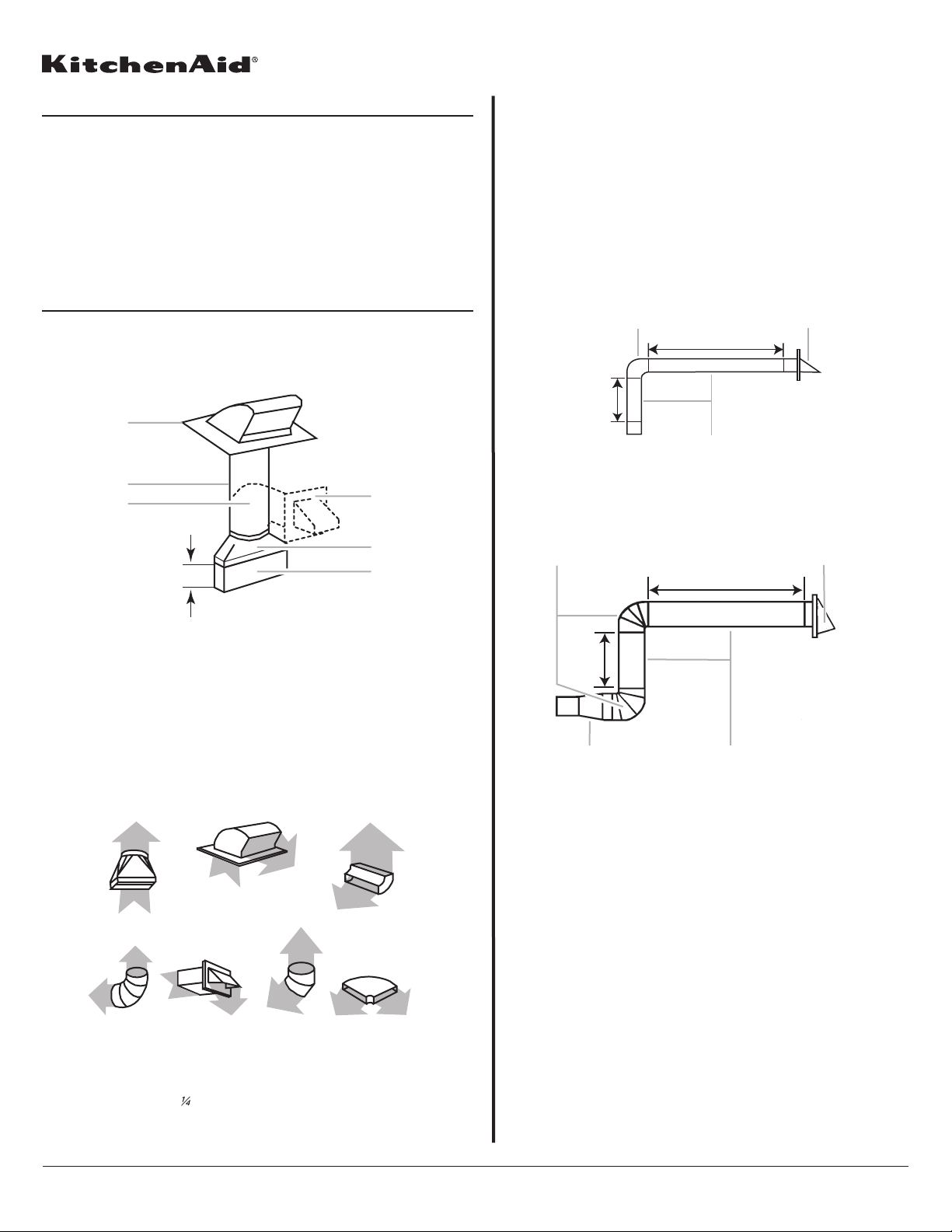
Rectangular to Round Transition
NOTE: The minimum 3" (7.6 cm) clearance must exist between the top of the
microwave oven and the rectangular to round transition piece so that the
damper can open freely and fully.
KHHC2090S KHMS2050S
E
D
Recommended Standard Fittings
The following length equivalents are for use when figuring vent length. See the
examples in “Recommended Vent Length.”
t
Recommended Vent Length
A 3¹⁄₄" x 10" (8.3 x 25.4 cm) rectangular or 6" (15.2 cm) round vent
should be used.
The total length of the vent system including straight vent, elbow(s),
transitions and wall or roof caps must not exceed the equivalent of
140 ft (42.7 m) for either type of vent. See “Recommended Standard
Fittings” section for equivalent lengths.
For best performance, use no more than three 90° elbows.
To calculate the length of the system you need, add the equivalent
lengths of each vent piece used in the system. See the following
examples:
3¹⁄₄" x 10" (8.3 x 25.4 cm) vent system = 73 ft (22.2 m) total
6" (15.2 cm) vent system = 73 ft (22.2 m) total
If the existing vent is round, a rectangular to round transition piece
must be used. In addition, a rectangular 3" (7.6 cm) extension vent
between the damper assembly and rectangular to round transition piece
must be installed to keep the damper from sticking.
Page 1 of 2
A
B
C
A B
6 ft (1.8 m)
2 ft
(0.6 m)
C
A. One 3
B. 1 wall cap = 40 ft (12.2 m)
C. 2 ft (0.6 m) + 6 ft (1.8 m) straight = 8 ft (2.4 m)
¹⁄₄
" x 10" (8.3 x 25.4 cm) 90° elbow = 25 ft (7.6 m)
3" (7.6 cm)
A. Roof cap
B. 6" (15.2 cm) min. diameter round vent
C. Elbow (for wall venting only)
D. Wall cap
E. 3
¹⁄₄
" x 10" to 6" (8.3 x 25.4 cm to 15.2 cm)
rectangular to round transition piece
F. Vent extension piece, at least 3" (7.6 cm) high
F
A B C
A B
6 ft (1.8 m)
2 ft
(0.6 m)
C D
A. Two 90° elbows = 20 ft (6.1 m)
B. 1 wall cap = 40 ft (12.2 m)
C. 1 rectangular to round transition piece = 5 ft (1.5 m)
D. 2 ft (0.6 m) + 6 ft (1.8 m) straight = 8 ft (2.4 m)
D E F G
A. Rectangular to round transition piece: 3
(8.3 x 25.4 cm to 15.2 cm = 1.5 m)
B. Roof cap: 3
C. 90° elbow: 3
D. 90° elbow: 6" = 10 ft (15.2 cm = 3 m)
E. Wall cap: 3
F. 45° elbow: 6" = 5 ft (15.2 cm = 1.5 m)
¹⁄₄
" x 10" = 24 ft (8.3 x 25.4 cm = 7.3 m)
" x 10" = 25 ft (8.3 x 25.4 cm = 7.6 m)
¹⁄₄
" x 10" = 40 ft (8.3 x 25.4 cm = 12.2 m)
¹⁄₄
" x 10" to 6" = 5 f
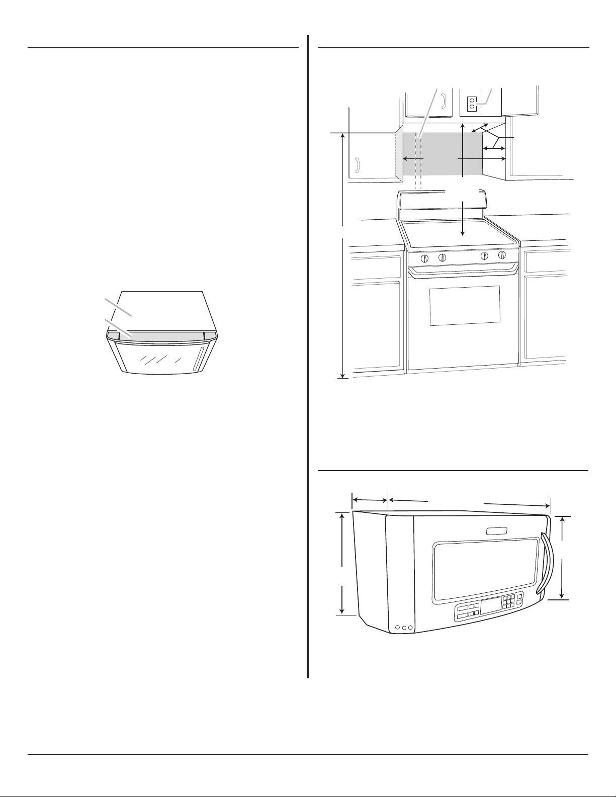
INSTALLATION DIMENSIONS
PRODUCT DIMENSIONS
g
NOTE: The grounded 3 prong outlet must be inside the upper cabinet.
See “Electrical Requirements” section.
* 33" (83.8 cm) is typical for 69" (175.3 cm) installation height. Exact
dimension may vary depending on type of range/cooktop below.
LOCATION REQUIREMENTS
Special Requirements
For Wall Venting Installation Only:
●
Cutout must be free of any obstructions so that the vent fits properly,
and the damper blade opens freely and fully.
For Roof Venting Installation Only:
●
If you are using a rectangular to round transition piece, 3" (7.6 cm)
clearance needs to exist above the microwave oven so that the damper
blade can open freely and fully. See “Rectangular to Round Transition”
illustration in “Venting Design Specifications” section.
Dimension Requirements
For proper ventilation, the vent screen must be free and clear of the
surrounding cabinetry. The maximum allowable upper cabinet and side
cabinet depth (from rear wall to front of cabinetry) must be no greater
than the depth of the microwave oven metal outer wrapper (from back of
microwave oven to the vent screen).
NOTE: If the upper cabinet is deeper than the maximum allowable depth
(see “Installation Dimensions”), then the installer must space the
microwave oven forward so that the vent screen is free and clear of any
surrounding cabinetry.
A
Because Whirlpool Corporation policy includes a continuous commitment to improve
our products, we reserve the right to change materials and specifications without notice.
Dimensions are for planning purposes only. For complete details, see Installation
Instructions packed with product. Specifications subject to change without notice.
Ref. W10502369A
11/6/12
Page 2 of 2
A
B
A B
12" (30.5 cm) min.
13" (33.0 cm) max.
upper cabinet and
side cabinet depth
69" (175.3 cm) min.
30"
(76.2 cm)
min.
(83.8 cm)
33"
typical*
. Microwave oven metal outer wrapper
B. Vent screen
A. 2" x 4" (5.1 x 10.2 cm) wall stud
B. Grounded 3 pron
outlet
"
¹⁄₄
18
4 cm)
.
46
"
¹⁄₄
18
(46.4 cm)
(
⁷⁄₈
9
2
(76.0 c
"
m)
(39
5
1
.
"
¹⁄₂
4 cm)
 Loading...