

Page 1

TECHNICAL EDUCATION
Over-The-Range
Microwave Oven
KAC-39
Model: KHMS175M
JOB AID 4317357
Page 2

FORWARD
This KitchenAid Job Aid, “Over-The-Range Microwave Oven,” (Part No. 4317357), provides the
technician with information on the installation, operation, and service of the Over-The-Range
Microwave Oven. It is to be used as a training Job Aid and Service Manual.
The Wiring Diagrams and Strip Circuits used in this Job Aid are typical and should be used for
training purposes only. Always use the Wiring Diagram supplied with the product when servicing
the unit.
GOALS AND OBJECTIVES
The goal of this Job Aid is to provide detailed information that will enable the service technician to
properly diagnose malfunctions and repair the Over-The-Range Microwave Oven.
The objectives of this Job Aid are to:
• Understand and follow proper safety precautions.
• Successfully troubleshoot and diagnose malfunctions.
• Successfully perform necessary repairs.
• Successfully return the Microwave Oven to its proper operational status.
WHIRLPOOL CORPORATION assumes no responsibility for any repairs made
on our products by anyone other than Authorized Service Technicians.
Copyright © 2004, Whirlpool Corporation, Benton Harbor, MI 49022
- ii -
Page 3

TABLE OF CONTENTS
Page
GENERAL............................................................................................................................... 1-1
Warning To Service Technicians ....................................................................................... 1-1
Precautions To Be Observed Before And During Servicing
To Avoid Possible Exposure To Excessive Microwave Energy ..................................... 1-2
R.F. Leakage Test ............................................................................................................. 1-3
Precautions To Be Observed When Troubleshooting ....................................................... 1-4
Model & Serial Number Designations ................................................................................ 1-5
Model & Serial Number Label And Tech Sheet Locations................................................. 1-6
Specifications..................................................................................................................... 1-7
KitchenAid Microwave Oven Warranty .............................................................................. 1-9
INSTALLATION INFORMATION ........................................................................................... 2-1
Adjusting The Exhaust Airflow ........................................................................................... 2-1
Removing & Reinstalling The Microwave Oven................................................................. 2-2
THEORY OF OPERATION ..................................................................................................... 3-1
Microwave Operation ......................................................................................................... 3-1
COMPONENT ACCESS ......................................................................................................... 4-1
Component Locations ........................................................................................................ 4-1
Removing The Cabinet ...................................................................................................... 4-2
Removing The Bottom Cover & Hood Lamp Socket ......................................................... 4-3
Removing Cavity Thermostat 1 & The Humidity Sensor ................................................... 4-4
Removing The Stirrer Motor .............................................................................................. 4-6
Removing Cavity Thermostats 2 & 3 ................................................................................. 4-8
Removing The Hood Exhaust Fan Motor ........................................................................ 4-10
Removing The Cavity Lamp & Socket ............................................................................. 4-11
Removing The Control Panel Assembly, The Power Supply
& Display Boards, And The Keyboard .......................................................................... 4-12
Removing An Inline Fuse................................................................................................. 4-14
Removing The AC Line Filter Capacitor .......................................................................... 4-15
Removing The Cooling Fan Motor, The Exhaust Fan Thermostat,
And The Line Fuseholder ............................................................................................. 4-16
Removing The Motor Capacitor, The Magnetron
Thermostat, & The 40 W Inverter Board ...................................................................... 4-18
Removing The 1100 W Inverter Board ............................................................................ 4-20
Removing The Magnetron ............................................................................................... 4-22
Removing The Primary & Secondary Interlock Switches,
And The Monitor Switch................................................................................................ 4-24
Removing The Turntable Motor ....................................................................................... 4-26
Removing The Oven Door And The Inner Panel ............................................................. 4-27
- iii -
Page 4

COMPONENT TESTING ........................................................................................................ 5-1
Door Switches.................................................................................................................... 5-1
Touch Panel Continuity...................................................................................................... 5-2
Stirrer & Turntable Motors ................................................................................................. 5-3
AC Line Filter Capacitor..................................................................................................... 5-3
Humidity Sensor ................................................................................................................ 5-4
Cavity Thermostats 1, 2, & 3 ............................................................................................. 5-4
Line Fuse & Exhaust Fan Thermostat ............................................................................... 5-5
Motor Capacitor ................................................................................................................. 5-5
Cooling Fan Motor ............................................................................................................. 5-6
Hood Exhaust Fan Motor ................................................................................................... 5-6
Magnetron.......................................................................................................................... 5-7
Magnetron Thermostat ...................................................................................................... 5-7
Inverters ............................................................................................................................. 5-8
DIAGNOSIS & TROUBLESHOOTING ................................................................................... 6-1
Power Output Measurement .............................................................................................. 6-1
Failure Codes .................................................................................................................... 6-1
Display And Power Board Callouts .................................................................................... 6-2
Primary, Secondary, & Monitor Switch Checks ................................................................. 6-3
Touch Panel & Microcomputer Board Test ........................................................................ 6-4
WIRING DIAGRAMS & STRIP CIRCUITS ............................................................................. 7-1
Schematic Diagram ........................................................................................................... 7-1
Wiring Diagram .................................................................................................................. 7-2
Strip Circuits ...................................................................................................................... 7-3
- iv -
Page 5

GENERAL
WARNING TO SERVICE TECHNICIANS
To avoid possible exposure to microwave radiation or energy, visually check the oven for
damage to the door and door seal before
operating any oven. Use a microwave survey
meter to check the amount of leakage before
servicing. In the event the R.F. Ieakage exceeds 4 mw/cm2 at 5 cm, appropriate repair
must be made before continuing to service the
unit. Check interlock function by operating the
door latch. The oven cook cycle should cut off
before the door can be opened.
The door and latching assembly contains the
radio frequency energy within the oven. The
door is protected by three safety interlock
switches. Do not attempt to defeat them.
Under no circumstances should you try to
operate the oven with the door open.
• Proper operation of microwave ovens requires that the magnetron be properly
assembled to the waveguide and cavity.
Never operate the magnetron unless it is
properly installed.
• Be sure the “RF” seal is not damaged and
is assembled around the magnetron dome
properly when installing the magnetron.
• Routine service safety procedures should
be exercised at all times.
• Untrained personnel should not attempt
service without a thorough review of test
procedures and safety information contained in this Job Aid.
KitchenAid microwave ovens have a monitoring system designed to assure proper operation of the safety interlock systems.
The monitor switch will immediately cause the
oven fuse to blow if the door is opened and the
primary door interlock switch and/or the secondary interlock switch contacts fail in a closed
position.
CAUTION: Replace a blown fuse with a 20
ampere class H fuse only.
Test the upper and lower door interlock
switches, cook relay, and monitor switch (middle
switch) for proper operation as described in the
component test procedures, before replacing
the blown oven fuse.
Do not attempt to repair sticking contacts
of any interlock switch, safety switch, or
Cook (Latch) relay. The components must
be replaced.
Any indication of sticking contacts during component tests requires replacement of that component to assure reliability of the safety interlock system.
If the fuse is blown, the Monitor switch, and
the Primary, and Secondary interlock
switches must be replaced. Be sure they
are properly connected.
1-1
Page 6

PRECAUTIONS TO BE OBSERVED BEFORE AND DURING
SERVICING TO AVOID POSSIBLE EXPOSURE
TO EXCESSIVE MICROWAVE ENERGY
A. Do not operate or allow the oven to be
operated with the door open.
B. Make the following safety checks on all
ovens to be serviced before activating the
magnetron or other microwave source,
and make repairs as necessary:
1)Interlock Operation
2)Proper Door Closing
3)Seal and Sealing Surfaces (Arcing,
Wear, and Other Damage)
4)Damage to or Loosening of Hinges and
Latches
5) Evidence of Dropping or Abuse
C. Before turning on the microwave power
for any service test or inspection within the
microwave generating components, check
the magnetron, wave guide or transmission line, and cavity for proper alignment,
integrity, and connections.
D. Any defective or misadjusted components
in the interlock, monitor, door seal, and
microwave generation and transmission
systems shall be repaired, replaced, or
adjusted, using procedures described in
this Job Aid, before the oven is released to
the owner.
E. A microwave leakage check to verify com-
pliance with the Federal Performance Standard should be performed on each oven
prior to release to the owner.
F. Do not attempt to operate the oven if the
door glass is broken.
1-2
Page 7

R.F. LEAKAGE TEST
EQUIPMENT
• Electromagnetic energy leakage monitor
(NARDA 8100B, HOLADAY H 1501 ).
• 275 ±15 ML glass beaker.
TEST
On every service call, checks for microwave
energy emission must be made according to
the following manner.
1. Remove the cooking rack from the oven
cavity, if the microwave oven is so
equipped.
2. Place a 275 ±15 ML (9.3 oz.) glass of
water in the center of the oven bottom.
3. Select "HIGH" cook power, turn the micro-
wave oven on, and test for R.F. Ieakage at
the following locations:
a)Around the cabinet at the front.
b)Around the door.
c) Across the console panel.
d)Horizontally across the door.
e)Vertically across the door.
f) Diagonally across the door.
g)Across the air vents.
h)Across the rear air vent.
i) All lockseams.
j) Weld at bottom.
k) Bottom plate.
I) Oven feet.
4. The scan speed is one inch per second.
When checking for R.F. Ieakage, use an approved R.F. measuring device to assure less
than 4 mw/cm2 emission at 5 cm distance with
a maximum scan rate of 2.54 cm/second, in
compliance with U.S. Government Department
of Health, Education and Welfare 21CFR1030,
Performance Standard for Microwave Ovens.
NOTE: Enter leakage readings in space BEFORE and AFTER on the service document.
All microwave ovens exceeding the emission
level of 4 mw/cm2 must be reported to Dept. of
Service for Microwave Ovens immediately and
the owner should be told not to use the microwave oven until it has been repaired completely.
If a microwave oven is found to operate with the
door open, report to Dept. of Service, the
manufacturer and CDRH* immediately. Also
tell the owner not to use the oven.
The monitor switch acts as the final safety
switch protecting the customer from microwave radiation. If the monitor switch operated
to blow the fuse when the interlocks failed, you
must replace all interlock switches with new
ones, because the contacts of those interlock
switches may be melted and welded together.
If safety interlock/monitor switch replacement,
or adjustment, is required, you must reconnect
the circuit, and perform a continuity check on
the monitor circuit.
All repairs must be performed in such a manner
that microwave energy emissions are minimal.
Address for CDRH is:
Office of Compliance (HFZ-312) Center for
Devices and Radiological Health
1390 Piccard Drive
Rockville, MD 20850
* CDRH: Center for Devices and Radiological Health,
Food and Drug Administration.
A properly operating door and seal assembly
will normally register small emissions, but they
must be no greater than 4 mw/cm2 to allow for
measurement uncertainty.
1-3
Page 8
PRECAUTIONS TO BE OBSERVED WHEN TROUBLESHOOTING
The microwave oven is a high voltage, high
current appliance. It is free from danger during
ordinary use, but extreme care should be taken
during repair.
VOLTAGE CAPACITORS
WARNING
DISCHARGING HIGH
CAUTION
Service technicians should remove their
watches whenever working close to or replacing the magnetron.
DANGER
HIGH VOLTAGE AND HIGH TEMPERA-
TURE (HOT/LIVE) OF THE INVERTER
POWER SUPPLY
The high voltage inverter power supply circuit supplies very high voltage and very high
current for the magnetron tube. Though it is
free from danger in ordinary use, extreme
care should be taken during repair. The
current is extremely large, and so danger
exists because of its high current and high
voltages.
The aluminum heat sink is also energized
with high voltage (HOT), so do not touch it
when the AC input terminal is connected to
the power line. One of the IGBT switching
power devices (collector) is directly connected to the aluminum heat sink.
The aluminum heat sink may be HOT from
heat energy; therefore, extreme care should
be taken during servicing and replacing.
For about 30 seconds after the oven is
turned off, an electric charge remains in the
high voltage capacitors in the inverter power
supply circuit board.
When replacing or checking parts, remove
the power plug from the outlet. Use a screwdriver with an insulated handle, and short the
inverter output of the magnetron filament
terminals to discharge it. Be sure to touch the
chassis ground side first, and then touch the
output terminals.
WARNING
There is high voltage present, with high
current capabilities in the circuits of the primary and secondary windings, the choke
coil, and the heat sink of the inverter. It is
extremely dangerous to work on or near
these circuits with the microwave oven energized. DO NOT measure the voltage in the
high voltage circuit, including the filament
voltage of the magnetron.
WARNING
Never touch any circuit wiring with your
hand, or with an insulated tool during operation.
WARNING
INVERTER POWER
SUPPLY GROUNDING
Check the high voltage inverter power supply circuit grounding. This high voltage inverter power supply circuit board must have
a proper chassis ground by the grounding
bracket to the chassis ground; otherwise,
this H.V. inverter circuit board will expose
very high voltage, and cause extreme DANGER. Be sure to have proper grounding by
the grounding plate and screws.
WARNING
Never insert a wire, nail, or any other metal
object through the lamp holes on the cavity,
or any other holes or gaps. Doing so may act
as an antenna, and cause microwave leakage.
WARNING
Before touching any oven components or
wiring, always unplug the oven from its
power source, and discharge the capacitors in the high voltage inverter.
1-4
Page 9

MODEL & SERIAL NUMBER DESIGNATIONS
MODEL NUMBER
MODEL NUMBER K H M S 1 7 5 M WH 0
PRODUCT GROUP
K = KITCHENAID BRAND
PRODUCT IDENTIFICATION
CM = COUNTERTOP MICROWAVE
HM = MICROWAVE HOOD
MERCHANDISING SCHEME
S = STANDARD
C = MICRO-CONVECTION
CAPACITY / SIZE / SERIES / CONFIGURATION
08 = 0.8 CU FT
10 = 1.0 CU FT
13 = 1.3 CU FT
14 = 1.4 CU FT
17 = 1.7 CU FT
FEATURES
2 = PLUS FEATURES
5 = DELUXE FEATURES
6 = MICRO-CONVECTION
7 = MICRO-CONVECTION WITH SENSOR
YEAR OF INTRODUCTION
M = 2003
COLOR CODE
WH = WHITE, BL = BLACK, BT = BISCUIT, SS = STAINLESS STEEL
ENGINEERING CHANGE (0, 1, 2, ETC.)
SERIAL NUMBER
SERIAL NUMBER T R P 4 0 10007
MANUFACTURING SITE
TR = Oxford, MS / Shunde
YEAR OF PRODUCTION
P = 2003
WEEK OF PRODUCTION
40TH WEEK
PRODUCT SEQUENCE NUMBER
1-5
Page 10
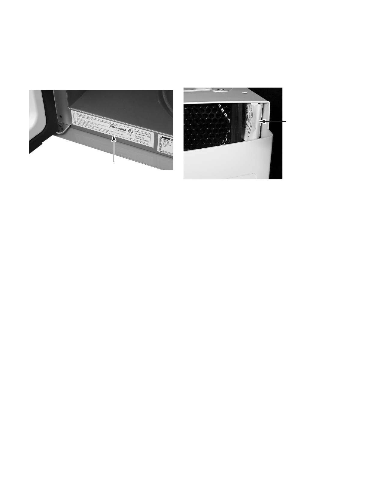
MODEL & SERIAL NUMBER LABEL
AND TECH SHEET LOCATIONS
The Model/Serial Number label and Tech Sheet locations are shown below.
Model & Serial
Number Label Location
Tech Sheet
Location
(Behind Grille)
1-6
Page 11
SPECIFICATIONS
MODEL KHMS175M
Colors White, Black, Biscuit , Stainless
CONTROL SYSTEM
Type Electronic
Limits 99 Min. 99 Sec.
Scale Linear (Digital)
2 Line Display with Multicolor Progress Bar
Display 5+2 Digit - Blue-Green
Fluorescent - Callouts In Display
In-Use Reprogramming Yes
More/Less Function Yes - Hidden "Cook Power" Button
Sales Demonstration Mode Yes - Hidden
Keypad Disable / Child Lockout Mode Yes - Press "Off/Cancel" Key for 5 Seconds
Cook Power Yes
Type Electronic
Range 0% - 100%
Scale Digital
Levels Ten
Exhaust Fan
Number of Speeds 5
Manual Off Yes
Auto Off No
Automatic Turn On @ 60°C, 140°F
Cooktop Light Halogen
Settings 3 levels HIGH, NIGHT & LOW
Wattage (2) 10 Watt Halogen
Light Cover Glass
Light "ON" When Cook Cycle Complete Yes
Stoppable Turntable Function / Button Yes
Technical Error Indication "F-" With Error Number
OVEN INTERIOR FEATURES
Size (inches) 22 7/8" W x 9 1/2" H x 14 1/2" D
Cooking Power 1100 Watts (IEC-705 Rating)
Turntable Yes, Sunken Flush
Glass turntable diameter 12"
Browning Pan Yes
Ventilation Axial blower
Cooling Fan Automatic - On if oven is operating,
Rack Yes
Light Automatic - Turns on when oven
door is open or oven is operating.
Sensor
Off if door open
10 Watt Halogen
1-7
Page 12
MODEL KHMS175M
DOOR FEATURES
Handle/Latch Yes/Pull to open
Seals Two Stage
(Capacitive and Reflective)
MICROWAVE SYSTEM
Distribution Top Feed with Stirrer
Magnetron Inverter Type
SAFETY FEATURES
Interlock Three Door/Latch Operated
Primary, secondary and monitor
Thermal Protectors Three - 1 Magnetron, 1 Oven Cavity, 1 Hood
VENTILATION SYSTEM
Type Convertible Recirculation or Exhaust Vertical/Horizontal
Duct Outlet Size 3 1/4"H x 10"W
Recirculation CFM Out 130
Exhaust CFM Out 175
Touch Control 5 Speed
Auto ON - High Speed YES: 60°C, 140°F
Noise Level Recirculation (Acc. to IEC 704) 67dBA
Shipped Recirculation mode
EXTERIOR FEATURES
Power Cord Length 3 Feet
OTHER SPECIFICATIONS
Electrical 120V, Single Phase, 60 Hz
1500 Watts, For Use With
15 - 20 Amp Circuit
Domestic Use Only Yes
Agency Approvals FCC, DHHS, CDRH, UL
Approx. Net Weight - Lb 63
APPROVED ACCESSORIES
Crisp Pan Yes
Exhaust Damper Assembly Yes (1 Set)
Hardware for Installation Yes (1 Set)
LITERATURE
Use & Care Guide Yes (Browning Pan instructions included)
Warranty In Use & Care Guide-1 Yr. Full, 2-5 Yr. Ltd. Mag. Tube
Tech Sheet 8185202
Job Aid 4317357
1-8
Page 13

KITCHENAID MICROWAVE OVEN WARRANTY
LENGTH OF
WARRANTY:
ONE-YEAR FULL
WARRANTY
From Date of
Purchase.
LIMITED FOURYEAR WARRANTY Second
through fifth year
from Date of
Purchase.
KITCHENAID
WILL PAY FOR:
Replacement parts
and repair labor
costs to correct
defects in materials or workmanship. Service must
be provided by a
KitchenAid-designated servicing
company.
Replacement
magnetron tube on
microwave ovens if
defective in materials or workmanship.
KITCHENAID
WILL NOT PAY FOR:
A. Service calls to:
1. Correct the installation of the microwave
oven.
2. Instruct you how to use the microwave
oven.
3. Replace house fuses or correct house
wiring.
4. Replace owner-accessible light bulbs.
B. Repairs when microwave oven is used in
other than normal single-family household
use.
C. Pickup and delivery. The microwave is de-
signed to be repaired in the home.
D. Damage to the microwave oven resulting
from accident, alteration, misuse, abuse, fire,
flood, acts of God, or use of products not
approved by KitchenAid.
E. Any labor costs during the limited warranty.
F. Repairs to parts or systems resulting from
unauthorized modifications made to the
appliance.
G. Replacement parts or repair labor costs for
units operated outside the United States.
KITCHENAID OR KITCHENAID CANADA DO NOT ASSUME ANY RESPONSIBILITY FOR
INCIDENTAL OR CONSEQUENTIAL DAMAGES. Some states or provinces do not allow the
exclusion or limitation of incidental or consequential damages, so this exclusion or limitation may
not apply to you. This warranty gives you special legal rights, and you may also have other rights
which vary from state-to-state or province-to-province.
Outside the United States and Canada, a different warranty may apply. For details, please
contact your authorized KitchenAid dealer.
If you need service first see the “Troubleshooting” section of the Use and Care Guide. After
checking ”Troubleshooting,” additional help can be found by checking the “Assistance or Service” section, or by calling our Customer Interaction Center telephone numbers, listed below,
from anywhere in the U.S.A. or Canada.
KitchenAid: 1-800-422-1230
Canadian Residents call: 1-800-807-6777
1-9
Page 14

— NOTES —
1-10
Page 15
Toward Top Of Unit
Blower Air Inlet
INSTALLATION INFORMATION
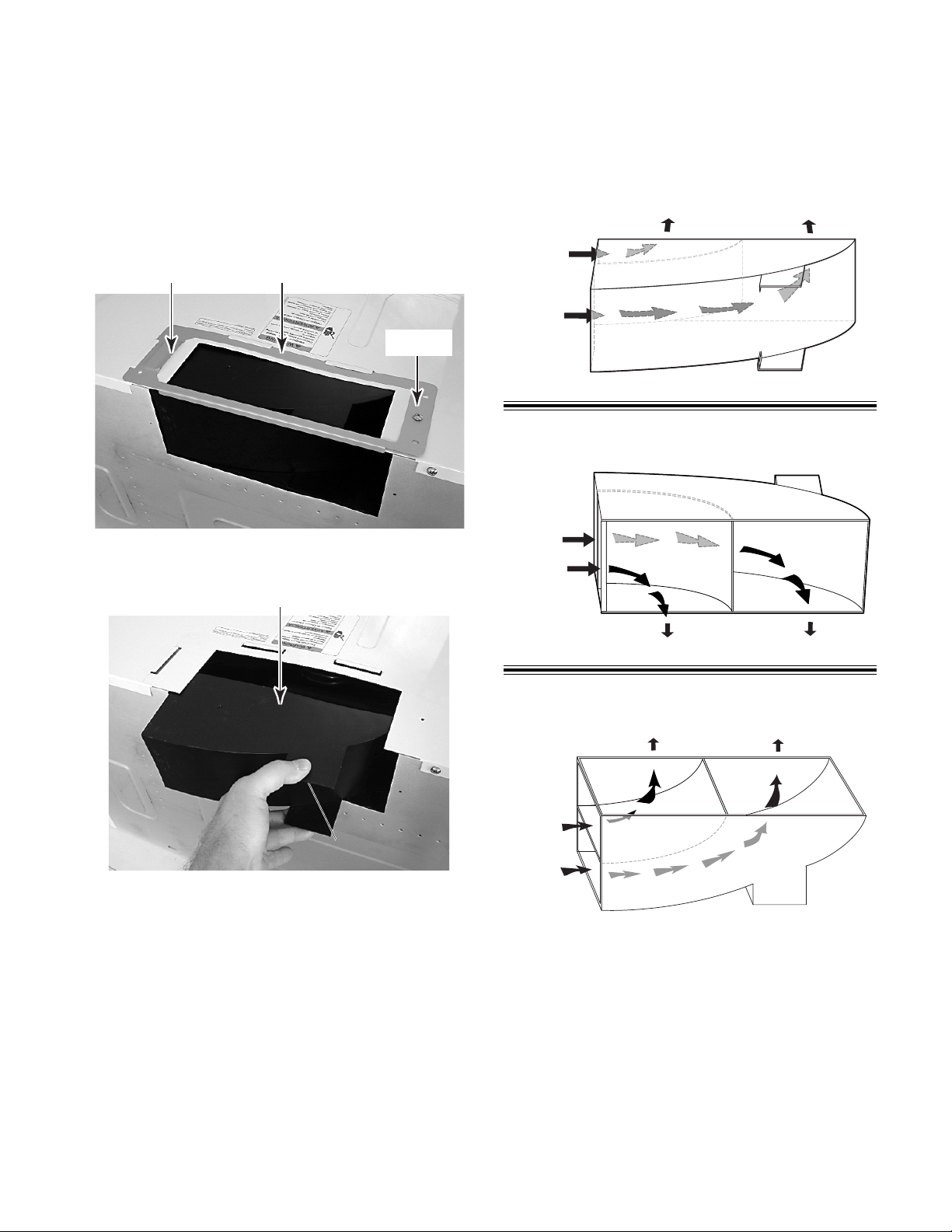
ADJUSTING THE EXHAUST AIRFLOW
1. Remove the screw from the damper plate
on top of the microwave cabinet, and
remove the plate from under the cabinet
flanges.
Flange
Damper Plate
Screw
2. Slide the air deflector out of the cabinet.
Air Deflector
Recirculating Air
Toward Front Of Unit
Blower Air Inlet
Rear Venting
Blower Air Inlet
3. Refer to the following illustrations and
determine how you would like to direct the
exhaust air out of the microwave oven.
NOTE: All microwave ovens are shipped
with the venting in the “recirculating” mode.
Toward Rear Of Unit
Top Venting
4. Rotate the air deflector so that the vanes
face in the desired direction, and slide the
air deflector back into the cabinet as far as
it will go, then reinstall the damper plate.
2-1
Page 16
REMOVING & REINSTALLING THE MICROWAVE OVEN
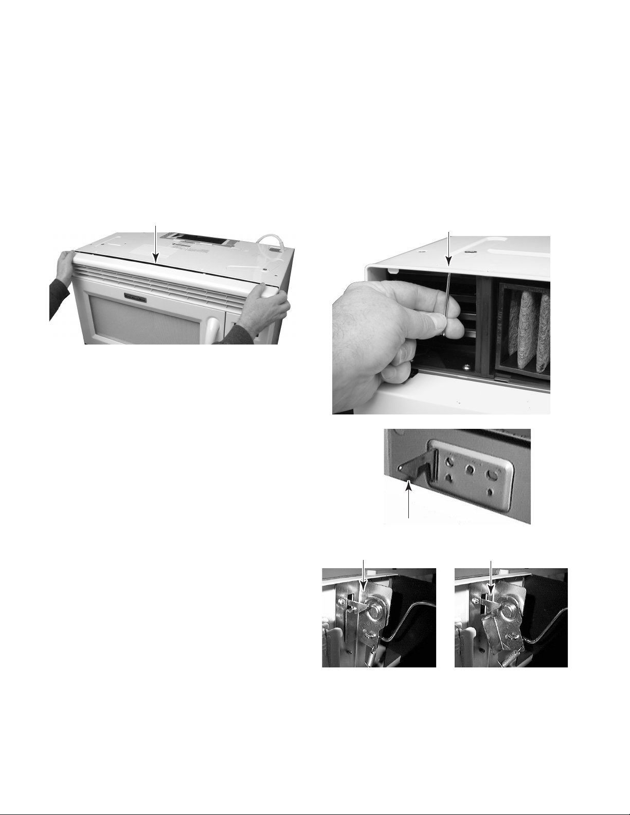
To remove the microwave oven:
1. Unplug the microwave oven or disconnect
the power.
2. Open the microwave oven door.
3. Pull the top of the air grille forward to
release the clips, then lift the grille, and
remove the bottom tabs from the cabinet
slots.
Pull Top Of Air Grille Forward
4. Remove the turntable and roller assembly.
CAUTION: Use two people to support the
microwave oven when you remove it from
its mounting location.
6. Remove the two bolts that secure the
microwave oven to the upper cabinet.
7. Hold the microwave oven in place with one
hand, and pull the latching arm forward to
release the latch from the rear mounting
plate clip.
Pull Latching Arm
5. Tape the door closed.
Clip On Rear Mounting Plate
Latch Engaged
Latch Released
2-2
Page 17
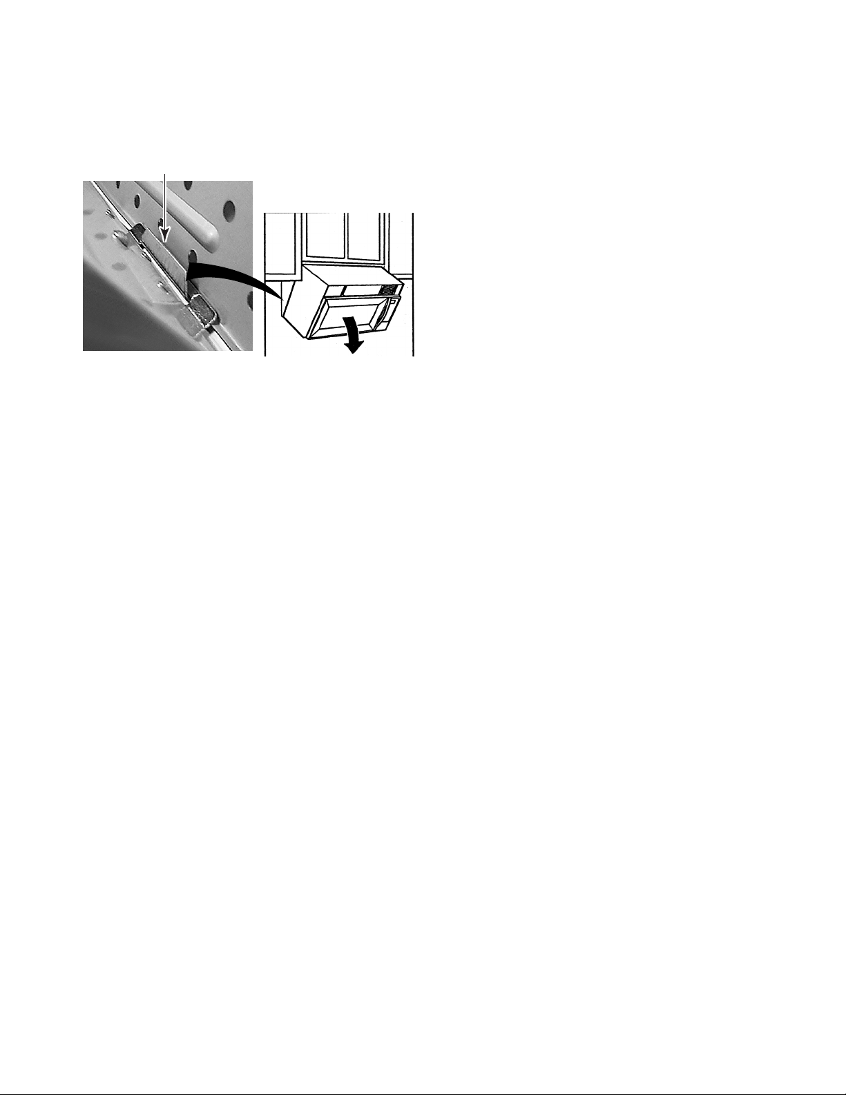
8. Rotate the microwave oven downward,
and lift the oven to unhook it from the
bottom of the mounting plate. Set the oven
on a protected surface.
Mounting Plate Hook
To reinstall the microwave oven:
1. Carefully lift the microwave oven and hang
it on the mounting plate hooks.
2. Rotate the front of the microwave oven
cabinet downward and insert the power
supply cord through the hole in the bottom
of the cabinet.
3. Rotate the microwave oven towards the
cabinet and push the oven against the
mounting plate until the clip snaps into the
cabinet.
4. Install the two bolts that secure the microwave oven to the upper cabinet.
Rotate Down
5. Install the air grille.
6. Remove the tape from the door and replace the turntable and roller assembly.
7. Plug in the microwave oven.
2-3
Page 18

— NOTES —
2-4
Page 19
THEORY OF OPERATION
MICROWAVE OPERATION
Traditional microwave technology is only able
to generate microwave energy at full power. In
order to reduce the power when cooking, defrosting, or reheating food, the microwave cycles
on and off, intermittently heating the food at full
power, so that the food is still heated with fullpower, but for less time. This makes it difficult
to achieve slow, or simmer-type cooking.
A microwave operates at full power whenever
the magnetron is on. Reducing the power level
only reduces the time that the magnetron is on.
50% Power Cycling On & Off
(Old Technology)
Newest developed technology has the ability
to control the level of microwave energy. When
cooking, defrosting, or reheating at reduced
power levels, the food receives constant energy that is evenly dispensed, producing true
slow, or simmer-type cooking.
50% Power On Continuously
(New Technology)
Old Technology New Technology
Power Level Magnetron On Magnetron Off Power Level Magnetron On Magnetron Off
0 0 Seconds 24 Seconds 0 0 Seconds 24 Seconds
1 4 Seconds 20 Seconds 1 24 Seconds 0 Seconds
2 6 Seconds 18 Seconds 2 24 Seconds 0 Seconds
3 8 Seconds 16 Seconds 3 24 Seconds 0 Seconds
4 11 Seconds 13 Seconds 4 24 Seconds 0 Seconds
5 13 Seconds 11 Seconds 5 24 Seconds 0 Seconds
6 16 Seconds 8 Seconds 6 24 Seconds 0 Seconds
7 18 Seconds 6 Seconds 7 24 Seconds 0 Seconds
8 20 Seconds 4 Seconds 8 24 Seconds 0 Seconds
9 22 Seconds 2 Seconds 9 24 Seconds 0 Seconds
10 24 Seconds 0 Seconds 10 24 Seconds 0 Seconds
3-1
Page 20
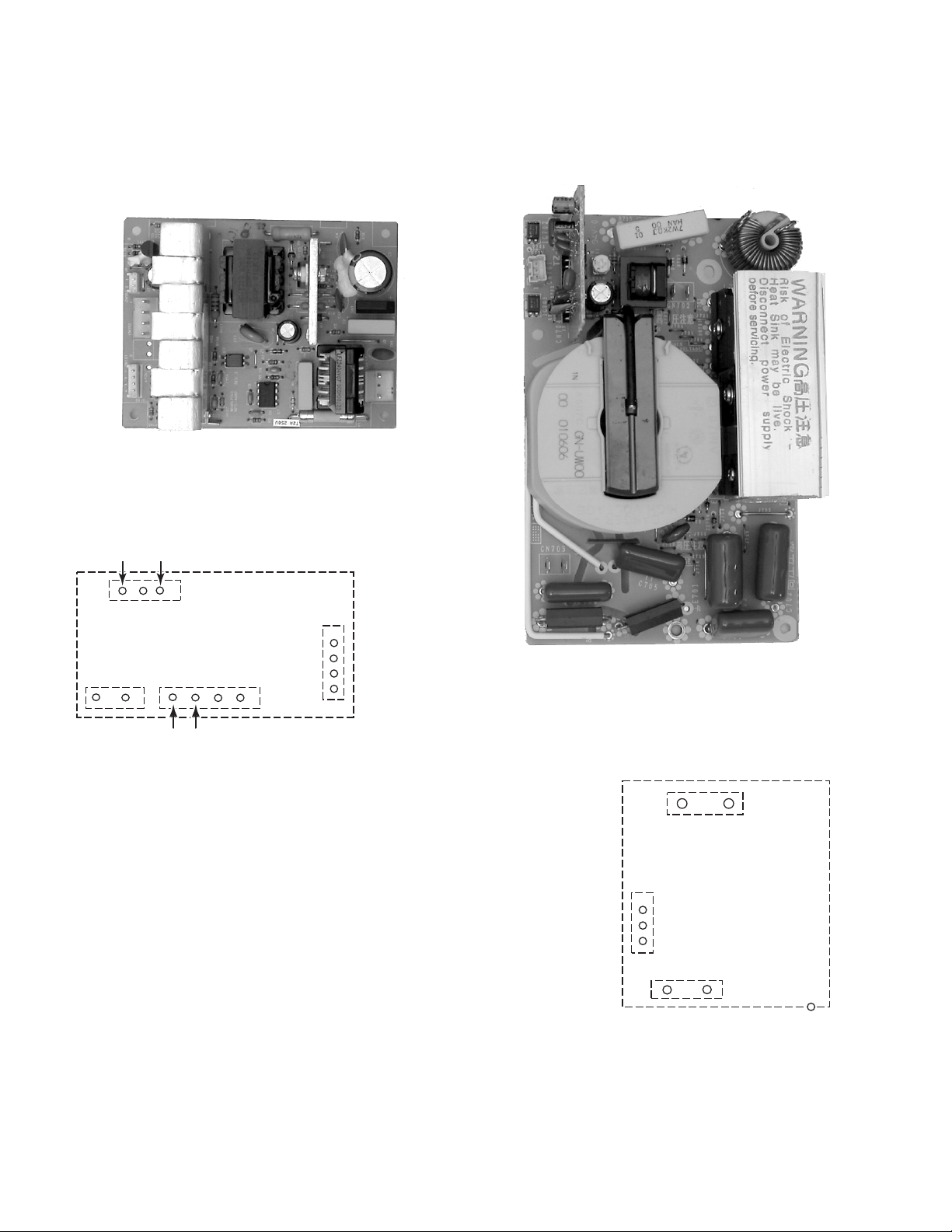
The power for the new Over-The-Range Microwave Oven is produced by 40 Watt and 1100
Watt inverters.
The 40 Watt inverter provides 12 volts DC to
operate the cooling fan and cavity lights.
40 W INVERTER
(Supplies 12 VDC To
Cooling Fan & Cavity Lights)
The 1100 Watt inverter replaces the high voltage transformer, capacitor, and diode to provide the necessary power to operate the magnetron.
120 VAC Input
1
CN1
40 W INVERTER
CN152CN153
1
To Cooling
Fan Motor
To Hood Lamp
40 W INVERTER CONNECTORS
CN151
1
1
Logic Circuit
To P3 On
Control Board
1100 W INVERTER
(Replaces The High Voltage
Transformer, Capacitor, & Diode)
120 VAC Input
CN702
1100 W INVERTER
Logic Circuit
To P2 Connector
On Control Board
1
CN701
CN703
E701
3-2
Voltage Output
To Magnetron
To Ground
1100 W INVERTER CONNECTORS
Page 21
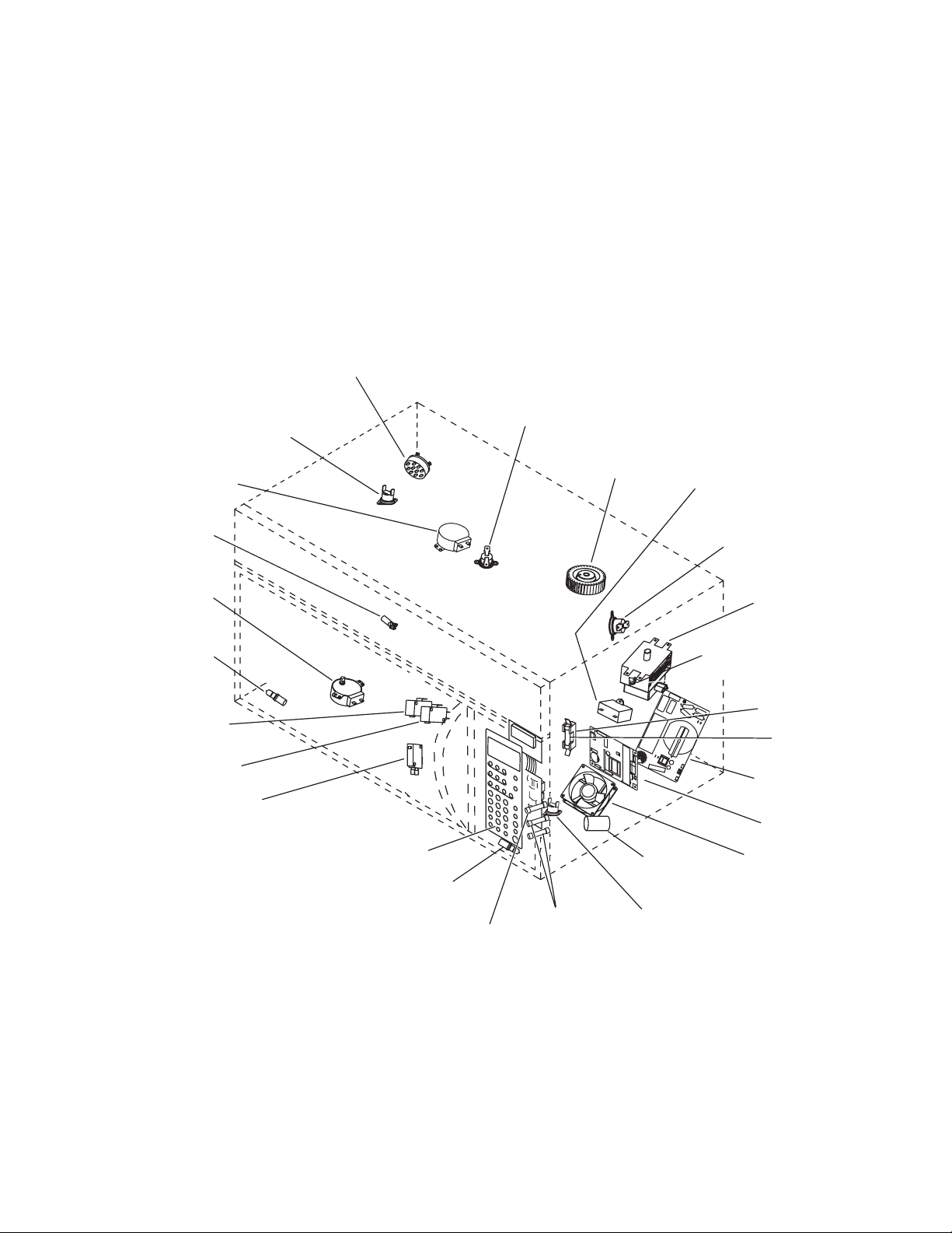
COMPONENT ACCESS
40W Inverter
Line Fuse
Cooling Fan
Motor
1100W Inverter
Magnetron
Cavity Lamp
Turntable Motor
Hood (Cooktop)
Lamp
Secondary Interlock
Switch
Primary Interlock
Switch
Hood (Cooktop) Lamp
Fuseholder
AC Line Filter
Capacitor
Control Panel Assembly
Monitor Switch
Magnetron Thermostat
Opens at 293°F (145°C)
Closes at 221°F (105°C)
Cavity
Thermostat 1
Closes at –31°F (–35°C)
Exhaust
Fan Thermostat
Opens at 104°F (40°C)
Closes at 140°F (60°C)
Stirrer Motor
Motor Capacitor
Hood Exhaust
Fan Motor
Cavity Thermostat 3
Opens at 257°F (125°C)
Closes at –31°F (–35°C)
Cavity Thermostat 2
Opens at 257°F (125°C)
Closes at –31°F (–35°C)
Fuse
(0.25 Amp.)
Fuse
(4 Amp.)
Humidity Sensor
Opens at 329°F (165°C)
This section instructs you on how to service each component inside the Over-The-Range
Microwave Oven. The components and their locations are shown below.
COMPONENT LOCATIONS
4-1
Page 22

REMOVING THE CABINET
WARNING
Electrical Shock Hazard
Disconnect power before servicing.
Replace all parts and panels before
operating.
4. Remove the eight screws from the back of
the unit.
Screw (1 of 8)
Back Of Unit
Failure to do so can result in death or
electrical shock.
1. Unplug microwave oven or disconnect
power.
2. Remove the microwave oven from its
mounting location (see page 2-2 for the
procedure).
3. Tip the oven on its rear panel and remove
the two cabinet bottom screws (one on
each side) from the bottom cover, then tip
the unit to its upright position.
Bottom Cover
5. Remove the power cord cover screw and
remove the cord cover.
6. Remove the six flat-head screws from the
top of the cabinet.
7. Remove the air duct by pulling it out the
back of the unit.
8. Pull the air filter forward and remove it.
9. Pull the cabinet back so that the two slots
on each side unhook from the tabs of the
front panel, and remove the cabinet from
the oven.
Screws
Slot
Slot
4-2
Page 23

REMOVING THE BOTTOM COVER & HOOD LAMP SOCKET
2. Remove the six screws from the bottom
WARNING
Electrical Shock Hazard
Disconnect power before servicing.
Replace all parts and panels before
operating.
Failure to do so can result in death or
electrical shock.
1. Unplug microwave oven or disconnect
power.
cover and lower the top edge of the cover.
Screw (1 of 6)
Bottom Cover
3. Disconnect the turntable motor connector
and the lamp connector.
4. Lift the rear edge of the bottom cover away
from the two tabs and lower the cover.
5. To remove a hood lamp socket and
lamp:
Lift The Rear Edge Of
The Bottom Cover
Away From Tabs
Lamp SocketLight Shield
a) Twist the socket and align the two tabs
with the hole slots, then pull the socket
out of the light shield hole.
b) Pull the pins of the lamp out of the
socket holes.
Turntable Motor
Connector
Lamp Connector
4-3
Hood Lamps
Page 24

REMOVING CAVITY THERMOSTAT 1
& THE HUMIDITY SENSOR
b) Press down on the locking tab in the
WARNING
holder and rotate the thermostat counterclockwise until it is free of the catches,
then lift it from the holder.
Electrical Shock Hazard
Disconnect power before servicing.
Replace all parts and panels before
operating.
Failure to do so can result in death or
electrical shock.
1. Unplug microwave oven or disconnect
power.
2. Remove the cabinet (see page 4-2 for the
procedure).
Cavity Thermostat 1 & Humidity Sensor
Cavity Thermostat 1
4. To remove the humidity sensor:
a) Remove the top screw from the control
panel, then lift the panel, unhook the
side latching tabs, and tilt the top forward.
Press Down On
Locking Tab
Control Panel Screw
3. To remove cavity thermostat 1:
a) Disconnect the wires from the thermo-
stat terminals.
4-4
Page 25

b) Disconnect the 3-wire (red, white, &
black) sensor connector from display
board connector P5.
Humidity Sensor Connector (P5)
c) Remove the two top cover screws from
the rear panel.
Screw
e) Remove the two screws and ground
wire from the sensor and remove the
sensor from the bracket.
f) Slide the top cover to the left and un-
hook the four front locking tabs in the
cover with the slots in the chassis, (see
the lower left photo).
g) Lift the top cover and pull the sensor
cable through the access hole, and
remove the sensor.
Ground Wire Screw
Ground Wire Screw
Screw
Humidity Sensor
Rear Panel
d) Remove the three top cover screws
from the front corners.
Screws
Top Cover
Screw
Screw
Position Humidity Sensor Cable Here
Access Hole
REASSEMBLY NOTE: When you reinstall the
humidity sensor on the bracket, be sure to
position the cable facing down, as shown in the
photo.
WARNING
Electrical Shock Hazard
Connect green ground wire to ground
screw.
4 Front Top Cover Locking Tabs
Failure to do so can result in death or
electrical shock.
4-5
Page 26

REMOVING THE STIRRER MOTOR
6. Lift the left end of the top cover and prop it
WARNING
up so you can access the stirrer motor.
Stirrer Motor
Wires
Electrical Shock Hazard
Disconnect power before servicing.
Replace all parts and panels before
operating.
Failure to do so can result in death or
electrical shock.
1. Unplug microwave oven or disconnect
power.
2. Remove the cabinet (see page 4-2 for the
procedure).
3. Remove the three front and two rear top
cover screws (see steps 4c and 4d on
page 4-5).
4. Remove the humidity sensor ground wire
screw from the rear panel.
Ground Wire Screw
Rear Panel
Screw (1 of 2)
Raise & Prop Up
Top Cover
7. Remove the screws from the motor and
disconnect the wire connectors from the
motor terminals.
8. Open the microwave oven door.
9. Use a putty knife and pry the stirrer motor
cover with the plastic nails and bushings
off the top of the oven cavity.
Humidity Sensor
5. Slide the top cover to the left and unhook
the four front locking tabs in the cover with
the slots in the chassis, (see photo in step
4d on page 4-5 for the tab locations).
Stirrer Motor Cover
4-6
Page 27

10. Carefully pull the mica cover off the stirrer
motor opening and remove the stirrer fan.
NOTE: The cover is held in place with
Selastic adhesive.
11. Use a piece of sandpaper and clean the
adhesive and other debris from around
the stirrer motor opening.
12. Install the new stirrer motor to the unit with
the two screws you removed earlier, and
connect the wires to the terminals.
13. Appy a 1/8″ bead of Selastic around the
unpainted area of the stirrer motor opening. Make sure that the bead goes completely around the opening with no breaks,
so that a complete seal is made between
the cover and the top of the oven cavity.
14. Install the stirrer fan onto the stirrer motor
shaft as far as it will go.
15. Place the mica cover over the stirrer motor
opening and align the four holes with those
in the oven cavity. Press the cover firmly
onto the adhesive, and install the four
bushings and plastic nails in the holes.
WARNING
Stirrer Fan On Motor Shaft
Clean Around Opening
Electrical Shock Hazard
Connect green ground wire to ground
screw.
Failure to do so can result in death or
electrical shock.
4-7
Page 28

REMOVING CAVITY THERMOSTATS 2 & 3
6. Lift the front of the top cover so you can
WARNING
access cavity thermostats 2 and 3, and
prop it up.
Electrical Shock Hazard
Disconnect power before servicing.
Replace all parts and panels before
operating.
Failure to do so can result in death or
electrical shock.
1. Unplug microwave oven or disconnect
power.
2. Remove the cabinet (see page 4-2 for the
procedure).
3. Remove the three front and two rear top
cover screws (see steps 4c and 4d on
page 4-5).
4. Remove the humidity sensor ground wire
screw from the rear panel (see step 4 on
page 4-6).
Cavity Thermostat 2
7. To remove cavity thermostat 2:
a) Fold back the paper insulator.
b) Remove the wires from the terminals.
c) Remove the two mounting screws.
Top Cover
Cavity Thermostat 3
5. Slide the top cover to the left and unhook
the four front locking tabs in the cover with
the slots in the chassis, (see photo in step
4d on page 4-5 for the tab locations).
Paper Insulator
Cavity Thermostat 2
4-8
Page 29

8. To remove cavity thermostat 3:
a) Remove the wires from the terminals.
b) Remove the two mounting screws.
Cavity Thermostat 3
4-9
Page 30

REMOVING THE HOOD EXHAUST FAN MOTOR
WARNING
Electrical Shock Hazard
Disconnect power before servicing.
Replace all parts and panels before
operating.
Failure to do so can result in death or
electrical shock.
1. Unplug microwave oven or disconnect
power.
2. Remove the cabinet (see page 4-2 for the
procedure).
Hood Exhaust Fan Motor
4. Remove the four hood exhaust fan motor
cover screws.
5. Remove the four hood exhaust fan motor
mounting screws and cup washers.
Hood Exhaust Fan Motor
Hood Exhaust Fan Motor
Mounting Screw (1 of 4)
Cover Screw (1 of 4)
Motor Wires
3. From the right side of the unit, disconnect
the 3-wire (red, white & black) hood exhaust fan motor connector from the main
harness connector.
Hood Exhaust Fan Motor Connector
Locking Tab (1 of 4)
Foam Tape
6. Carefully remove the tape from over the
motor wires, then press in on the four
locking tabs, and lift the cover off the hood
exhaust fan motor.
7. Remove the hood exhaust fan motor.
Hood Exhaust Fan Motor
4-10
Page 31

REMOVING THE CAVITY LAMP & SOCKET
5. Unscrew the bulb from the cavity lamp
WARNING
socket.
6. To remove the cavity lamp socket, twist
the socket to the left (counterclockwise) to
unlock it, and push it out of the mounting
hole.
Electrical Shock Hazard
Disconnect power before servicing.
Replace all parts and panels before
operating.
Failure to do so can result in death or
electrical shock.
1. Unplug microwave oven or disconnect
power.
2. Open the microwave oven door.
3. Pull the top of the air grille forward to
release the clips, then lift the grille, and
remove the bottom tabs from the cabinet
slots.
Pull Top Of Air Grille Forward
Cavity Lamp Socket
Bulb
7. Disconnect the wires from the socket terminals.
4. Lift the front of the cavity lamp cover
slightly and pull it out of the slot in the top
cover.
Cavity Lamp Cover
Socket Wires
4-11
Page 32

REMOVING THE CONTROL PANEL ASSEMBLY,
THE POWER SUPPLY & DISPLAY BOARDS,
AND THE KEYBOARD
WARNING
Electrical Shock Hazard
Disconnect power before servicing.
Replace all parts and panels before
operating.
Failure to do so can result in death or
electrical shock.
1. Unplug microwave oven or disconnect
power.
b) Disconnect wire connectors P2, P3,
P5, P12, and P14 from the display and
power supply boards.
c) Disconnect the wires from the relay
terminals.
d) Remove the green ground wire from
the control panel bracket.
e) Unhook the hinge from the slot and
remove the control panel assembly from
the unit.
f) Lay the control panel assembly on a
padded surface.
Red & Org Red
P14
Relay
2. Remove the air grille from the unit (see
page 4-11 for the procedure).
3. To remove the control panel assembly:
a) Remove the top screw from the control
panel, then lift the panel, unhook the
side latching tabs, and tilt the top forward as far as the wires will allow.
Control Panel Screw
Ground
P12
P5
P3 P2
WARNING
Electrical Shock Hazard
Connect green ground wire to ground
screw.
4-12
Failure to do so can result in death or
electrical shock.
Page 33

4. To remove the power supply & display
boards:
a) Disconnect wire connector P7 from the
display board.
b) Lift the locking arm by the two end tabs
and remove the two ribbon cables from
connector P6.
c) Remove the screw from the display
board and unclip it from the locking
arms.
d) Remove the two screws from the power
supply board and unclip it from the
locking arms.
e) Remove the power supply and display
boards from the control panel.
Lift Tab
Lift Tab
5. To remove the keyboard:
a) Unclip the bracket and remove it from
the panel.
Bracket
b) Remove the two screws from the key-
board and unclip it from the panel.
c) To replace the display window on the
control panel, unclip the two tabs.
Keyboard
Display Window
Power Supply Board
P6
Screw
Screws
P7
Screw (1 of 2)
Display Board
4-13
Page 34

REMOVING AN INLINE FUSE
WARNING
Electrical Shock Hazard
Disconnect power before servicing.
Replace all parts and panels before
operating.
Failure to do so can result in death or
electrical shock.
1. Unplug microwave oven or disconnect
power.
6. Unsnap the two tabs from the locking arms
on the fuseholder for the inline fuse you
are removing.
Locking Arms & Tabs
On Inline Fuseholder
2. Remove the air grille (see page 4-11 for
the procedure).
3. Open the microwave oven door.
4. Remove the control panel assembly (see
page 4-12 for the procedure).
5. Determine which of the three inline fuses
you need to remove.
3 Inline Fuses
7. Open the fuseholder, slide the ends of the
wire connectors off the ends of the fuse,
and remove the fuse.
Slide Wire Connectors
Off Ends Of Fuse
4-14
Page 35

REMOVING THE AC LINE FILTER CAPACITOR
WARNING
Electrical Shock Hazard
Disconnect power before servicing.
Replace all parts and panels before
operating.
Failure to do so can result in death or
electrical shock.
1. Unplug microwave oven or disconnect
power.
2. Remove the air grille from the unit (see
page 4-11 for the procedure).
4. Discharge the 1100 W inverter (perform
steps 3 and 4 on page 4-20).
5. Remove the AC line filter capacitor from
the cooling fan motor and cut the wires
from the capacitor leads.
AC Line Filter Capacitor
3. Remove the control panel assembly (see
page 4-12 for the procedure).
Cut Both Wires
6. Splice the wires coming from the new
capacitor to the cut harness wires, and
twist a pair of wire nuts over the ends of the
cut wires.
7. Use a large bead of Selastic and adhere
the capacitor to the fan.
4-15
Page 36

REMOVING THE COOLING FAN MOTOR, THE EXHAUST
FAN THERMOSTAT, AND THE LINE FUSEHOLDER
4. To remove the cooling fan motor:
WARNING
Electrical Shock Hazard
Disconnect power before servicing.
Replace all parts and panels before
operating.
Failure to do so can result in death or
electrical shock.
1. Unplug microwave oven or disconnect
power.
2. Remove the air grille from the unit (see
page 4-11 for the procedure).
3. Remove the control panel assembly (see
page 4-12 for the procedure).
a) Press out on the top side locking tabs,
lift the fan, and pull it forward to remove
it.
b) Disconnect the 2-wire fan motor con-
nector from connector CN153 on the
40 W inverter board.
40 W Inverter Board
Fan Motor
Connector
CN153
Locking
Tabs
Line Fuseholder
Cooling Fan Motor
Exhaust Fan
Thermostat
Located Behind Control Panel
Cooling Fan Motor
REASSEMBLY NOTE: When you reinstall the
cooling fan motor, be sure to seat the bottom
corners in the panel slots.
Bottom Corners In Slots
4-16
Page 37

5. To remove the exhaust fan thermostat:
6. To remove the line fuseholder:
a) Remove the cooling fan motor to make
accessing the thermostat easier (see
step 4 for the procedure).
b) Disconnect the wire connectors from
the thermostat terminals.
c) Press down on the locking tab with a
screwdriver blade, turn the thermostat
so the flange is over the top of the tab,
and lift the thermostat body out of the
mounting hole.
2 BrnYel & Wht
Wire Connectors
a) Disconnect the wire connectors from
the fuseholder terminals.
b) Remove the fuse from the fuseholder.
Brn
Wire
Connectors
Red & Org
Line
Fuse
Press Tab
Down
Lift
Exhaust Fan
Thermostat
c) Remove the screw from the fuseholder.
Fuseholder
Screw
Turn
4-17
Page 38

REMOVING THE MOTOR CAPACITOR, THE MAGNETRON
THERMOSTAT, & THE 40 W INVERTER BOARD
4. To remove the motor capacitor, remove
WARNING
Electrical Shock Hazard
Disconnect power before servicing.
the phillips screw and disconnect the wire
connectors from the terminals.
Screw
Replace all parts and panels before
operating.
Failure to do so can result in death or
electrical shock.
1. Unplug microwave oven or disconnect
power.
2. Remove the air grille from the unit (see
page 4-11 for the procedure).
3. Remove the control panel assembly (see
page 4-12 for the procedure).
Magnetron Thermostat
Motor Capacitor
Motor Capacitor
Red - Wire Connectors - Wht
5. To remove the magnetron thermostat,
remove the two phillips screws and disconnect the wire connectors from the terminals.
Magnetron Thermostat
40 W Inverter Board
Located Behind Control Panel
4-18
Screw
2 Blu
Wire Connectors
Gry
Screw
Page 39

6. To remove the 40 W inverter board:
a)Disconnect the wire connectors from:
b) Raise the two top locking arms and
remove the inverter board.
CN1
CN151
CN152
CN153
Locking Arms
CN153
CN152
CN151
CN1
4-19
Page 40

REMOVING THE 1100 W INVERTER BOARD
WARNING
Electrical Shock Hazard
Disconnect power before servicing.
Replace all parts and panels before
operating.
5. Remove the 40 W Inverter Board (see
page 4-19 for the procedure).
6. Remove the exhaust fan thermostat (see
page 4-17 for the procedure).
7. Disconnect the red and white wires from
the motor capacitor, the blue and gray
wires from the magnetron thermostat, and
the brown, red, and orange wires from the
line fuseholder terminals.
8. Remove the two screws from the front
mounting panel.
Failure to do so can result in death or
electrical shock.
1. Unplug microwave oven or disconnect
power.
2. Remove the control panel assembly (see
page 4-12 for the procedure).
3. Remove the cooling fan motor (see page
4-16 for the procedure).
NOTE: Make sure to read the “Warnings” on
page 1-4 before you continue.
4. Hold a 20,000Ω (red-black-orange)
2-Watt resistor by the body with a pair of
long nosed pliers, and touch the leads to
the two discharge points on the 1100 W
inverter. Be careful not to touch the bare
resistor leads during this procedure.
Screw
Magnetron
Thermostat
(Blu & Gry)
Line
Fuseholder
(Brn, Red,
& Org)
Screw
Motor
Capacitor
(Red &
Wht)
Front
Mounting
Panel
9. Pull the front mounting panel out the front
of the unit, then remove the wires from the
side of the panel.
Front Mounting Panel
Discharge Points
Remove
Wires
4-20
Page 41

10. Disconnect the two magnetron wires from
the 1100 W inverter (CN703) and remove
them from the cover.
11. Lift the cover off the 1100 W inverter and
remove it from the unit.
Remove Magnetron Wires
Cover
13. Remove the 2 red and 2 gray wires from
the inverter terminals at CN702.
14. Release the locking arm on the 3-wire
cable at CN701 and disconnect it.
15. Remove the mounting screw from the
board and unsnap the 1100 W inverter
from the holder.
Ground Wire
2 Red & 2 Gry
(CN702)
Magnetron Wires (CN703)
12. Remove the top and bottom mounting
screws from the 1100 W inverter holder.
Slide the holder to the right so the slot is
over the tab at the bottom, and remove the
holder and inverter.
Holder Mounting Screw
Mounting Screw
3-Wire Cable CN701
16. Remove the screw and nut from the green
ground wire and remove the wire from the
1100 W inverter.
WARNING
Electrical Shock Hazard
Holder Mounting Screw
Connect green ground wire to ground
screw.
Failure to do so can result in death or
electrical shock.
Slot
4-21
Page 42

REMOVING THE MAGNETRON
WARNING
Electrical Shock Hazard
Disconnect power before servicing.
Replace all parts and panels before
operating.
Failure to do so can result in death or
electrical shock.
1. Unplug microwave oven or disconnect
power.
2. Remove the air grille from the unit (see
page 4-11 for the procedure).
5. Discharge the 1100 Watt inverter as follows. NOTE: Make sure that the screwdriver touches ground before touching the
magnetron terminals.
a) Use a plastic handle screwdriver and
touch the metal tip to the case of the
magnetron.
b) Touch the screwdriver shaft against
either of the two magnetron terminals
for approximately 5 seconds.
Touch The Screwdriver Tip
To The Magnetron Case
3. Remove the cabinet (see page 4-2 for the
procedure).
4. Remove the control panel assembly (see
page 4-12 for the procedure).
Magnetron
1100 W
Inverter Board
Touch The Screwdriver Shaft
To Either Magnetron Terminal
Front Mounting Panel Rear Mounting Panel
4-22
Page 43

6. Remove the screw from the front mounting panel.
Front Mounting Panel Screw
7. Bend the metal tab back, then slide the
two rear mounting panel tabs toward the
right side, and lower them through the
cutouts in the chassis.
8. Disconnect the two filament wires from the
magnetron terminals.
9. Remove the four mounting screws from
the magnetron. NOTE: Pull the front mount-
ing panel forward so you can access the
two front screws.
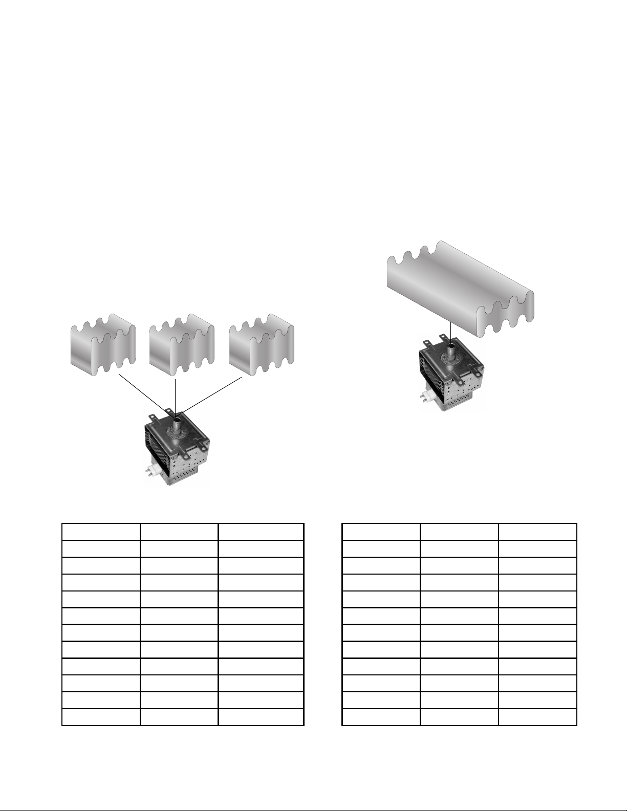
REASSEMBLY NOTE: When you reinstall the
magnetron, insert the alignment pins into their
holes at the back of the magnetron.
Magnetron
Screw (1 of 4)
Rear Mounting Panel Tabs
Lower The Rear Panel
Bend Metal Tab Back
Filament Wires
Front Panel
4-23
Page 44

REMOVING THE PRIMARY & SECONDARY INTERLOCK
SWITCHES AND THE MONITOR SWITCH
5. To remove the secondary interlock
WARNING
Electrical Shock Hazard
Disconnect power before servicing.
switch or the monitor switch:
a) Unsnap the linking rod and remove it.
b) Carefully bend the two locking arms
back and pull the switch off the two
pins.
c) Remove the wire connectors from the
switch terminals.
Replace all parts and panels before
operating.
Failure to do so can result in death or
electrical shock.
1. Unplug microwave oven or disconnect
power.
2. Remove the air grille (see page 4-11 for
the procedure).
3. Open the microwave oven door.
4. Remove the control panel assembly (see
page 4-12 for the procedure).
Monitor
Switch
Linking Rod
Secondary
Interlock
Switch
Org-Yel
(COM.)
White (COM)
2 Blue (N.O.)
Brn-Yel (N.C.)
Red-Wht
(N.O.)
6. To remove the primary interlock switch:
a) Grip the top and bottom of the linking
rod with your fingers and carefully pull
back on the switches so that they spring
to their fully retracted position.
4-24
Pull Back
Forward
Linking
Rod
Retracted
Pull Back
Page 45

b) Use a T10 torx screwdriver and remove
the two screws from the interlock switch
assembly.
c) Pull the switch assembly away from the
front chassis and position it so that you
can access the primary interlock switch.
REASSEMBLY NOTES:
1. When reinstalling the switch assembly
after performing step 6, be sure to hook
the plastic tabs, at the top and bottom of
the switch holder, into the slotted metal
retainers in the chassis, as shown below.
Make sure that the metal retainers are not
bent up so that the tabs will not fit into
them. Otherwise, the switches may not
operate properly.
T10 Torx
Screws
Primary Interlock Switch
Locking Arm
Blu-Blk (COM)
White (N.O.)
Pin
Metal
Retainer
Slot
Switch
Holder
Tab
2. After installing the switch assembly, rotate
the linking rod and two switches to their
forward position (see the photos in step
6a). Close and open the door several
times to make sure that the switches operate normally. If not, check step 1 above for
proper installation, as well as the forward
position of the switches.
d) Carefully unhook the two locking arms
and pull the switch off the two pins.
e) Remove the wire connectors from the
switch terminals.
4-25
Page 46

REMOVING THE TURNTABLE MOTOR
WARNING
Electrical Shock Hazard
Disconnect power before servicing.
Replace all parts and panels before
operating.
Failure to do so can result in death or
electrical shock.
2. Remove the cabinet (see page 4-2 for the
procedure).
3. Open the microwave oven door and remove the spindle from the turntable motor
shaft.
Turntable Spindle
(Inside Oven Cavity)
1. Unplug microwave oven or disconnect
power.
Turntable Motor
4. Remove the bottom cover from the microwave oven (see page 4-3 for the procedure).
5. Remove the screws from the turntable
motor and remove it.
Screws
4-26
Page 47

REMOVING THE OVEN DOOR AND THE INNER PANEL
4. Place the oven door front side down on a
WARNING
Electrical Shock Hazard
Disconnect power before servicing.
padded surface.
5. Remove the choke screws from the door
frame.
Replace all parts and panels before
operating.
Failure to do so can result in death or
electrical shock.
1. Unplug microwave oven or disconnect
power.
2. Open the microwave oven door.
3. Pry the choke cover away from the top
door pin, and remove the top pin from the
pivot bracket. Lift the door off the bottom
bracket, and remove it.
Top Door Pin
Pry Out Choke
Cover Here
Pivot Bracket
Choke Screws
6. Starting at the top right corner, (see the
round inset photo in the left column), pry
the choke cover out with a putty knife, and
unsnap it from the choke. Only remove the
top, bottom and right sides of the choke
cover at this time. You will remove the
handle end of the choke cover later.
Door Frame
Unsnap Choke Cover
Continued on the next page.
Choke Cover
Choke
4-27
Page 48

7. Starting at the top edge of the door near
the center and working clockwise, use a
putty knife, and pry the latching tabs of the
choke out of the door frame slots. Lift the
choke as you release the tabs so they do
not snap back into the slots. NOTE: When
you reach the handle side of door, pull
both the choke and the choke cover away
from the door frame, and then separate
the two components.
DOOR COMPONENTS
Choke Cover
Pry Out
Tab
Putty Knife
Choke With Switch Actuators
Door Frame With Outer
Glass (Plastic) & Handle
REASSEMBLY NOTE: When you reinstall the
door on the oven, insert the top pin into the
pivot bracket and press down on the pin until it
snaps into place.
8. To remove the door switch actuators from
the choke, remove the screw from each
actuator.
Choke
Screw
Door Switch Actuators
Screw
4-28
Page 49

COMPONENT TESTING
Discharge the 1100 W inverter before conducting any of the following tests (perform steps 1
through 4 on page 4-20).
All operational checks using microwave energy must be done with the microwave oven
loaded with a minimum of 275 ml (9.3 oz.) of
water in a microwave safe container.
Electrical Shock Hazard
Disconnect power before servicing.
Replace all parts and panels before operating.
Failure to do so can result in death or electrical shock.
DOOR SWITCHES
Conduct a microwave energy test after performing any tests or repairs to the microwave.
Check that all wire leads are in the correct
position before operating the microwave oven.
Grasp wire connectors when removing the
wire leads from microwave parts.
WARNING
Refer to page 4-24 for the procedure for servicing the door switches.
1. Unplug microwave oven or disconnect
power.
2. Disconnect the wires from the switch terminals.
3. Set the ohmmeter to the R x 1 scale.
4. Touch the ohmmeter test leads to the
terminals of the primary or secondary
interlock switch (normally-open). The
meter should indicate an open circuit (infinite).
Normally-Open
Normally-Closed
5. Touch the ohmmeter test leads to the
terminals of the monitor switch (normally-
closed). The meter should indicate a closed
circuit (0 Ω).
NOTE: Pressing the actuator button should
result in opposite readings (normally-open
should read closed, and normally-closed should
read open).
5-1
Page 50

WARNING
Electrical Shock Hazard
Disconnect power before servicing.
Replace all parts and panels before operating.
Failure to do so can result in death or electrical shock.
TOUCH PANEL CONTINUITY
To test the touch panel, perform the following
steps:
1. Unplug microwave oven or disconnect
power.
2. Disconnect the ribbon cable from the control board connector P7.
CONNECTOR (P7)
1
1 2 3 4 5 6 7 8 9 10 11 12 13 14 15 16 17 18
RIBBON CABLE
PIN #
7
(On/Night/Off)
8
3456
Vent Fan
5 speeds
Light
Clock
3. Set the ohmmeter to the R x 1 scale.
4. Use a pair of alligator clips and clip them to
the ribbon contact numbers shown along
the top and side of the indicated keyboard
matrix, shown below.
For example:
a) Install alligator clips over contacts 5 and
17 of the ribbon cable.
b) Touch the alligator clips with the test
leads.
c) Press the BEVERAGE keypad. The
meter should indicate a resistance of
approximately 200 Ω.
Turntable
On/Off
9
Timer
Set/Off
10
11
12
13
14
15
16
17
18
1
2
7
Add a
Minute
1
Cook
Time
Reheat
Popcorn
ESD ground plane
Cook
Power
Cook
Dinner
Plate
Baked
Potato
5-2
0
5
4
9
Browning
6
23
Keep
Warm
Defrost
Beverage
START
Pan
Boil &
Simmer
Melt
Soften
Cancel
OFF
8
Page 51

WARNING
Electrical Shock Hazard
Disconnect power before servicing.
Replace all parts and panels before operating.
Failure to do so can result in death or electrical shock.
STIRRER & TURNTABLE MOTORS
Refer to pages 4-6 and 4-26 for the procedures
for servicing the stirrer and turntable motors.
1. Unplug microwave oven or disconnect
power.
2. Disconnect the wire connectors from the
motor under test.
3. Set the ohmmeter to the R x 1K scale.
4. Touch the ohmmeter test leads to the
stirrer motor terminals . The meter should
indicate between 3300 and 4200 Ω.
5. Touch the ohmmeter test leads to the turntable motor terminals. The meter should
indicate between 2700 and 3800 Ω.
AC LINE FILTER CAPACITOR
Test Point
Test Point
Refer to page 4-15 for the procedure for servicing the AC line filter capacitor.
1. Unplug microwave oven or disconnect
power.
2. Discharge the 1100 W inverter (perform
steps 2 through 4 on page 4-20).
3. Set the ohmmeter to the R x 1000 scale.
4. Touch the ohmmeter test leads to the bare
wires near the capacitor body (you may
have to pull the insulation back slightly).
The meter should briefly indicate approximately 10K ohms, and then gradually return towards infinity.
5-3
Page 52

WARNING
Electrical Shock Hazard
Disconnect power before servicing.
Replace all parts and panels before operating.
Failure to do so can result in death or electrical shock.
HUMIDITY SENSOR
Refer to page 4-4 for the procedure for servicing the humidity sensor.
1. Unplug microwave oven or disconnect
power.
2. Disconnect the 3-wire connector from the
control board.
3. Set the ohmmeter to the R x 1K scale.
4. Touch the ohmmeter test leads to the
indicated wire terminals of the 3-wire connector. The meter should indicate as follows:
Black to white = approximately 2800 Ω
@ 77˚F/25˚C.
White to red = approximately 2800 Ω
@ 77˚F/25˚C.
CAVITY THERMOSTATS 1, 2, & 3
Refer to pages 4-4 and 4-8 for the procedures
for servicing the cavity thermostats.
1. Unplug microwave oven or disconnect
power.
2. Disconnect the wires from the terminals.
3. Set the ohmmeter to the R x 1 scale.
4. Touch the ohmmeter test leads to the
terminals. The meter should indicate a
closed circuit (0 Ω).
NOTE: Thermostat 1 opens @ 329°F / 165°C.
Thermostats 2 and 3 open @ 257°F / 125°C . I f
the thermostat is defective, the ohmmeter will
indicate an infinite circuit.
5-4
Page 53

WARNING
Electrical Shock Hazard
Disconnect power before servicing.
Replace all parts and panels before operating.
Failure to do so can result in death or electrical shock.
LINE FUSE & EXHAUST
FAN THERMOSTAT
Line Fuse
Refer to page 4-16 for the procedures for
servicing the line fuse and the exhaust fan
thermostat.
1. Unplug microwave oven or disconnect
power.
2. Set the ohmmeter to the R x 1 scale.
3. To test the line fuse, touch the ohmmeter
test leads to the ends of the fuse. The
meter should indicate a closed circuit
(0 Ω).
Exhaust Fan
Thermostat
MOTOR CAPACITOR
Refer to page 4-18 for the procedure for servicing the motor capacitor.
1. Unplug microwave oven or disconnect
power.
2. Discharge the 1100 W inverter (perform
steps 2 through 4 on page 4-20).
3. Disconnect the wires from the terminals.
4. Set the ohmmeter to the R x 10K scale.
5. Touch the ohmmeter test leads to the
capacitor terminals. The meter should indicate several thousand ohms and gradually return to infinity.
4. To test the exhaust fan thermostat:
a) Disconnect the wires from the termi-
nals.
b) Touch the ohmmeter test leads to the
terminals. The meter should indicate an
open circuit (infinite). NOTE: The thermostat closes @ 140˚F / 60˚C, and will
reset (open) @ 104˚F / 40˚C.
5-5
Page 54

WARNING
Electrical Shock Hazard
Disconnect power before servicing.
Replace all parts and panels before operating.
Failure to do so can result in death or electrical shock.
COOLING FAN MOTOR (12 VDC)
Refer to page 4-16 for the procedure for servicing the cooling fan motor.
1. Unplug microwave oven or disconnect
power.
2. Disconnect the wire connectors from the
cooling fan motor terminals.
3. Set the ohmmeter to the R x 1 scale.
4. Touch the ohmmeter test leads to the
motor terminals. The meter should indicate
between 17 and 28 Ω.
5. An additional test for the cooling fan motor
is as follows (see the photo below):
a) Connect a battery connector to a fresh
9 volt battery.
b) Connect the red wire from the battery
connector to the red wire in the fan connector, and the black wire to the black
wire in the fan connector.
HOOD EXHAUST FAN MOTOR
(120 VAC)
Refer to page 4-10 for the procedure for servicing the hood exhaust fan motor.
1. Unplug microwave oven or disconnect
power.
2. Disconnect the hood exhaust fan motor
connector from the main harness connector.
3. Set the ohmmeter to the R x 1 scale.
4. Touch the ohmmeter test leads to the
motor terminals. The meter should indicate
as follows:
White to black = 30 to 60 Ω.
Red to black = 40 to 80 Ω.
Cooling Fan Motor
9 Volt Battery
5-6
Page 55

WARNING
Electrical Shock Hazard
Disconnect power before servicing.
Replace all parts and panels before operating.
Failure to do so can result in death or electrical shock.
MAGNETRON
Filament Terminals
Refer to page 4-22 for the procedure for servicing the magnetron.
1. Unplug microwave oven or disconnect
power.
2. Discharge the 1100 W inverter (perform
step 5 on page 4-22).
3. Disconnect the wire connectors from the
filament terminals.
MAGNETRON THERMOSTAT (N.C.)
Refer to page 4-18 for the procedure for servicing the magnetron thermostat.
1. Unplug microwave oven or disconnect
power.
2. Disconnect the wires from the magnetron
thermostat terminals.
3. Set the ohmmeter to the R x 1 scale.
4. Touch the ohmmeter test leads to the
terminals. The meter will indicate a closed
circuit (0 Ω) at room temperature. NOTE:
The thermostat opens @ 293˚F / 145˚C
and resets (closes) @ 221˚F / 105˚C.
4. Set the ohmmeter to the R x 1 scale.
5. Touch the ohmmeter test leads to the
filament terminals. The meter should indicate less than 1 Ω.
6. Touch one ohmmeter test lead to the
chassis and the other to each of the filament terminals. The meter should indicate
an open circuit (infinite).
5-7
Page 56

WARNING
Electrical Shock Hazard
Power is present during the following
tests.
INVERTERS
MEASURING OVEN INPUT CURRENT
1. Remove the screw from the power cord
retaining plate and remove the plate.
2. Pull the power cord out of the cabinet and
separate the wires.
3. Connect an ammeter clamp around the
white power cord wire.
Ammeter Clamp Around
Power Cord
White Power Cord Wire
Control Power
Supply Board
Test Leads
Power Cord Retaining Plate
4. Turn the microwave oven On.
5. Check the ammeter for a 15A reading.
• If the ammeter indicates more than 0.5
amps, check the magnetron and its
wiring.
• If the ammeter indicates less than 0.5
amps, it indicates that there is no input
to the 1100 W inverter. Check for the
following:
- No AC voltage supply or control signal. Check the control power supply
board at the relay terminals for 120
VAC (see the photos at the top of the
next column).
Relay
WARNING
Electrical Shock Hazard
Disconnect power before servicing.
Replace all parts and panels before
operating.
Failure to do so can result in death or
electrical shock.
1100 W INVERTER
Refer to page 4-20 for the procedure for servicing the 1100 W inverter.
IMPORTANT: HIGH VOLTAGE—DO NOT
MEASURE!
5-8
Page 57

NOTE: Refer to the “Warnings” on page 1-4.
Do not attempt to repair, or make any adjustments to the inverter board.
Check Wiring
1. Unplug microwave oven or disconnect
power.
WARNING
2. Discharge the 1100 W inverter (perform
steps 2 through 4 on page 4-20).
3. Visually inspect inverter board connectors
CN701, CN702, CN703, and E701. Check
for signs of failure due to loose wiring,
unseated connectors, and discoloration
due to overheating.
CN701
(I/O Signal)
CN702
(120 VAC)
Electrical Shock Hazard
Disconnect power before servicing.
Replace all parts and panels before
operating.
Failure to do so can result in death or
electrical shock.
40 W INVERTER
Refer to page 4-18 for the procedure for servicing the 40 W inverter.
Check Wiring
1. Unplug microwave oven or disconnect
power.
2. Visually inspect inverter board connectors
CN1, CN151, CN152, and CN153. Check
for signs of failure due to loose wiring,
unseated connectors, and discoloration
due to overheating.
CN703
(High Voltage Output
To Magnetron)
E701
(Ground)
CN153 & CN152 (12 VDC)
CN151 (Signal Input)
Continued on the next page.
CN1 (120 VAC Input)
5-9
Page 58

WARNING
4. Connect power to the microwave oven.
5. Open the oven door.
6. Touch the voltmeter test probes to pins 1
and 2 of connector CN152 (refer to the
photo on the previous page). The meter
should indicate 12 volts DC.
Electrical Shock Hazard
Power is present during the following
tests.
Check DC Output Voltage
1. Unplug microwave oven or disconnect
power.
2. Tilt the control panel back so you can
access the 40 W inverter board.
3. Set the voltmeter to measure 12 volts DC.
NOTE: The 40 W inverter output voltages that
will be tested in the following steps are shown
in the chart below.
Connector Test Points
Pins 1 & 2
Output
Voltage
12 volts DCCN152
Pins 3 & 4
CN153* Pins 1 & 2 12 volts DC
* Test in “Demo Mode.”
7. Close the oven door.
8. Press the LIGHT keypad on the control
panel and set the lights to full intensity.
NOTE: Do not press the LIGHT keypad
during the measurement.
9. Touch the voltmeter test probes to pins 3
and 4 of connector CN152. The meter
should indicate 12 volts DC.
10. Press and release the CANCEL/OFF keypad.
11. Press and hold the TIMER keypad until a
small “d” appears on the display, (after
approximately 5 seconds), then release
the keypad.
12. Turn the microwave oven on.
13. Touch the voltmeter test probes to pins 1
and 2 of connector CN153. The meter
should indicate 12 volts DC.
14. Press and release the CANCEL/OFF keypad.
15. Press and hold the TIMER keypad until
the small “d” disappears from the display
and release the keypad.
5-10
Page 59

DIAGNOSIS & TROUBLESHOOTING
POWER OUTPUT MEASUREMENT
The power output of the magnetron can be
measured using the following test. Before you
perform the test:
• Make sure that the microwave oven
cavity is clean and cool.
• Check the line voltage at the microwave
oven and note the reading.
1. Fill a glass beaker with 32 oz. (1000 ml) of
tap water.
2. Stir the water with a thermometer and record
the temperature. The temperature should
be between 50° and 75°F (10° and 24°C).
FAILURE CODES
3. Place the beaker of water in the center of
the microwave oven cavity.
4. Operate the microwave oven on high power
for 1 minute.
5. Remove the beaker of water and stir it with
the thermometer for about 20 seconds.
6. Record the temperature of the water.
7. Subtract the temperature of the water you
recorded in step 2 from the water temperature in step 6. The normal rise in temperature range is shown in the following chart.
Voltage
(VAC Under Load)
120 12 - 15 22 - 26
108 10 - 12 19 - 21
Temperature Rise
°C °F
Display LikelyFailureCondition
Flashing
colon “:”
-F2-
-F3H-
-F3T
-F7-
Power Failure
Keyboard Failure
Humidity Sensor
Failure
Temperature Sensor
Failure
Power to Magnetron
Interrupted
Recommended Repair Procedure
After a power failure, the colon “:” will be flashing. Press any key to end this
indication. The colon will then be steady when in standby.
1. Unplug microwave oven or disconnect power.
2. Replace membrane switch.
3. Plug in microwave oven or reconnect power.
4. If problem persists, go to step 5.
5. Unplug microwave oven or disconnect power.
6. Replace control system assembly.
1. Unplug microwave oven or disconnect power.
2. Connect a new sensor to the board (at P5).
3. Plug in microwave oven or reconnect power.
4. If no failure code appears when starting sensor function:
– Unplug microwave oven or disconnect power.
– Replace sensor.
5. Otherwise:
– Unplug microwave oven or disconnect power.
– Replace control system assembly.
1. Check that the oven temperature is not below 41°F (5°C) or above 140°F (60°C).
2. If problem persists:
– Unplug microwave oven or disconnect power.
– Replace control system assembly.
1. Unplug the oven for at least 40 seconds. Check to see if this solves the problem.
(Possible reason: Overtemperature protection for the magnetron operated earlier.)
2. Unplug microwave oven or disconnect power.
3. Check the resistance of the magnetron thermostat. It should be close to 0 ohms.
4. Check the magnetron.
5. Check wiring to the 1100 W inverter and control system.
6. Check operation of all interlock switches.
7. If switches operate correctly,
– Unplug microwave oven or disconnect power.
– Replace 1100 W inverter.
8. If problem persists, replace control system assembly.
NOTE: If lights work, but cooling fan does not, 40W inverter may have failed.
6-1
Page 60

DISPLAY AND POWER BOARD CALLOUTS
Touch Panel
(Membrane
Switch)
Interlock
Secondary
Switch
1100W
Inverter
DISPLAY PCB
P6
1
MCU
P2
P3
P11 P21
P5
R
P11 P21
Ribbon
Cable/3C
1
1100W
Inverter
CN701
1
1
1
1
Ribbon
Cable/4C
1
BK
W
40W
Inverter
CN151
Humidity
Sensor
POWER PCB
4903
MW
RELAY
R
R
2
1
P14
4906
4901
1
L.V.T.
TR1 - 5101
Fuse
0.25 Amp.
Magnetron Thermostat
Turntable Motor
Stirrer Motor
BK:
BLACK
BU:
BLUE
R:
RED
W:
G:
Y:
WHITE
GREEN
YELLOW
1
O
O
BU
R
GY
BR:
BROWN
O:
ORANGE
GY:
GRAY
P12
G
Fuse
4Amp.
BR
Fuse
4Amp.
Y
Exhaust Fan Thermostat
6-2
Page 61

PRIMARY, SECONDARY, & MONITOR SWITCH CHECKS
Primary Interlock
Monitor Switch
Monitor Interlock
Switch
Secondary Interlock
Switch
Switch Check By
Door
Open
Door
Closed
1. Unplug microwave oven or disconnect power.
Primary
Interlock
2. Disconnect the wires at the Primary Interlock Switch.
3. Check from the common terminal (Blue/Black wires) to
– +
the normally open terminal (White wire).
1. Unplug microwave oven or disconnect power.
Secondary
Interlock
2. Disconnect the wires at the Secondary Interlock Switch.
3. Check from the common terminal (Orange/Yellow wires)
–
+
to the normally open terminal (White/Red wires).
1. Unplug microwave oven or disconnect power.
Monitor
2. Disconnect the wires at the Monitor Switch.
3. Check from the common terminal (White/Blue wires) to
+
–
the normally closed terminal (Yellow/Brown wires).
(+) Continuity No Continuity
(–)
NOTE: These diagrams are not intended to show a complete circuit. They represent the position
of the switches during “Door Open” and “Door Closed” (continuity checks only).
DOOR CLOSED DOOR OPEN
L
(C)
Interlock Switch
(N.O.)
(N.C.)
Secondary
(C) (C)
(N.O.)
(N.C.)
Monitor Switch
Interlock Switch
(N.O.)
(N.C.)
Primary
N
L
(C)
Interlock Switch
(N.O.)
(N.C.)
Secondary
(C) (C)
(N.O.)
(N.C.)
Monitor Switch
Interlock Switch
(N.O.)
(N.C.)
Primary
N
6-3
Page 62

TOUCH PANEL & MICROCOMPUTER BOARD TEST
The microwave oven has a self-diagnostic test
that can be accessed through the touch panel
keypad. To perform the test:
1. Be sure power is connected to the microwave oven and that the door is closed.
NOTE: You will have to access the touch panel
and the power cord plug in the next step. If you
cannot access them both, have another person available to help you with the step.
2. Perform the following sequence to enter
the touch panel “self-test” mode:
a)Press and hold the CANCEL/OFF key-
pad.
b)Open the oven door.
c) Unplug the power cord plug for 2 sec-
onds and then plug it back in.
d)Release the CANCEL/OFF keypad and
close the door.
3. Press each touch panel keypad, as shown
in the Key Table to the right. As you do, the
number “8” should appear in the display
position shown in the chart, to indicate that
the circuits are complete, and that the relays are working properly.
NOTE: If you should press the CANCEL/OFF
keypad during any of the tests, you will exit the
test mode. Perform step 2 to reenter the test
mode.
21
3
54
Key Name Function
Popcorn 1
Baked Potato
Dinner Plate
Beverage
Reheat
Cook
Defrost
Keep Warm
Soften
Melt
Broil & Simmer
Browning Pan
1
2
3
Cook Time
4
5
6
Cook Power
7
8
9
Add a Minute
Timer Set/Off
0
Clock Buzzer
CLOCK Buzzer
Light
On/Night/Off
Vent Fan
5 Speeds
Turntable
On/Off
Start
Cancel
OFF
–
–
–
–
–
Humidity Sensor
–
–
–
–
–
–
Relay 4901 1
Hood Light
Relay 4903
–
–
–
Relay 4906 3
–
–
–
Hood Fan Triac
–
–
–
–
–
–2
–
–
Exit Test Mode –
Display
Position*
2
3
5
1
3
5
1
2
3
4
2
3
5
1
2
5
1
2
3
5
1
2
3
3
1
3
5
6-4
“ 8” will appear in the display position indicated in the table.
*
Display position 1 is farthest to the left. Display position 5 is
farthest to the right.
Eight seconds after pressing COOK, “Hmxxx” will appear in
the display (xxx = humidity reading).
Page 63

WIRING DIAGRAMS & STRIP CIRCUITS
SCHEMATIC DIAGRAM
41 Y/G
CN701
E701
CN703
40 W
39 W
MAGNETRON
WIRE COLOR - BROWN
WIRE NO. - 1
38 R
Filter Capacitor
49 GY
50 GY
37 R
1100W
CN702
TER
INVER
1
25 BU
5P11
29 R
28 W
Y
INTERLOCK
SECONDAR
9Y
TT
27 BK
31 BU
26 BU
6P11
SM
Sensor
Humidity
30 O
FUSE
53 O
34 R
35 GY
0.25 Amp.
BKRW
P14
1
1
12
DoorTT
NFS
SM
CL
P5
4903
TT
4906
Relay
SM
4901
Relay
TR1-5101
L.V.T.
Relay
MW
7103
Sec.
Prim.
46 26AWG/3C
1
P2
PCB
Y PCB
DISPLA
& POWER
P3
1
HF
HL
L1
N1
1
P12
FUSE
51 G
BR
11
52 BR
4 Amp.
FUSE
17 BK
12 Y
4Amp.
16 G
BK
Fan
10 BR
Exhaust
Thermostat
13 W
14 W
2P10
1P10
BK
BU
31
R
15
BK
HF
Magnetron
INTERLOCK
Motor Capacitor
3P10
9Y
50 GY
1BR
Thermostat
32 BU
MONITOR
33 W
PINK
BROWN
ORANGE
GRAY
P:
O:
BR:
GY:
WHITE
GREEN
YELLOW
Y:
G:
W:
TRANSPARENT
BLACK
BLUE
RED
R:
TR:
BK:
BU:
ORS
P2/P3/P5/P12/P14/CN1/CN151/
CN152/CN153/CN701/CN702/CN703:
WIRE TO PCB CONNECT
ORS
P0/P10/P11:
WIRE TO WIRE CONNECT
RIBBON CABLE/3C(4C)
26AWG/3C(4C):
8O
FUSE
1BR
20 Amp.
7R
120V / 60Hz
45 26AWG/4C
1
TER
CN151
CL
P
P
1
40W
CN152
1
CN153
21 W
22 Y
R
BK
Cavity
Thermostat-2
INVER
1
CN1
19 BU
2P0
BK
L
2BU
1P0
W
G
GND
N
3BU
Cavity
Thermostat-1
4BU
TR
23 W
HL
HL
Y
TR
1P11
Cavity
Thermostat-3
Y
W
24
2P11
CF
PRIMARY
INTERLOCK
HOOD EXHAUST
HF
NOTES
18 BU
SYMBOL
OR
FAN MOT OR
TURNTABLE
MOT
TT
HOOD LAMP
(COOKTOP LAMP)
CAVITY LAMP
HL
CL
OPEN
CONDITION:
DOOR
OR
D.C. COOLING
FAN MOT
CF
OR
STIRRER MOT
SM
7-1
Page 64

AT
MAGNETRON
THERMOST
BU BU
WIRING DIAGRAM
GY
GY
TER
FIL
CAPACITOR
R
1100W
INVERTER
CN702
SWITCH
BU
Y
INTERLOCK
PRIMAR
INTERLOCK
MONITOR SWITCH
BU
BU
BU
BU
W
BK
BR
G
BK
O
& FUSE SADDLE
FUSE
BR
VITY
CA
THERMOSTAT-3
BR
AT-2
CAVITY
THERMOST
AT-1
VITY
CA
THERMOST
TWO POLES
W
R
BU
P0
OR
CONNECT
CORD
POWER
BU
40W INVERTER
CN153
OR
FAN MOT
DC COOLING
BR
Y
O
INTERLOCK
SUPPORT
BU
CN152
1
1
W
P
P
R
Y
&
BK
CAVITY LAMP
1
P2
CN1
CN151
1
HOLDER
CAVITY LAMP
CABLE/4C
RIBBON
1
MCU
1
P3
Y
INTERLOCK
SECONDAR
SWITCH
R
W
W
Y
W
HUMIDITY
SENSOR
P5
BK
BU
R
6
6
BK
1
5
4
3
12
BK
R
5
4
123
OR
SIX POLES
CONNECT
W
BU
1
P1
Y PCB
DISPLA
P11 P21
BU
R
BK
BR
GY
MOTOR
STIRRER
ABLE
OR
MOT
TURNT
W
W
Y
&
LAMP HOLDERS
HOOD LAMPS
HOOD
TR
TR
RIBBON CABLE/3C
PCB
POWER
P11 P21
Y
CABLE/3C
RIBBON
.
L.V.T
4901
4906
MW
4903
TR1 -5101
Y
RELA
1
CN701
CN703
Y/G
W
W
MAGNETRON
R
BU
BK
BR
OR
FAN MOT
HOOD EXHAUST
OR
POLES
BK
BK
BK
1
1
BK
W
G
BR
SADDLE
R
FUSE & FUSE
G
1
P14
R
2
1
O
R
P10
2
3
CONNECT
THREE
2
3
R
W
BR
SADDLE
FUSE & FUSE
Y
BR
P12
O
1
OR
MOT
W
ACITOR
CAP
FAN
EXHAUST
GY
R
BU
GY
R
THERMOSTAT
FUSE &
FUSE SADDLE
R
BU
R
BK:
BLACK
BU:
BLUE
R:
RED
TR:
TRANSPARENT
W:
G:
Y:
WHITE
GREEN
YELLOW
BR:
O:
GY:
BROWN
ORANGE
GRAY
7-2
Page 65

STRIP CIRCUITS
N
MICROWAVE COOKING
MICROCOMPUTER BOARD
2P12
R
3P14
4P14
1P14
1
2
3
4
LOW VOLTAGE
TRANSFORMER
TR1-5101
TTM RELAY
4906
DOOR RELAY
4901
MW RELAY
2
4903
P3
DISPLAY PCB
POWER PCB
CAVITY LAMP
&
FUSE
4Amp.
L1
BK
INTERLOCK
SECONDARY
SWITCH
FUSE
20 Amp.
BR
R
BU
BR
BR
TURNTABLE MOTOR
BU
Y
STIRRER MOTOR
BK
W
O
1
CN1
3
40W
INVERTER
2.7 - 3.8k
3.3 - 4.2k
0.25 Amp.
TT
SM
FUSE
1
2
3
CN151
4
1
2
CN153
1
2
CN152
R
BR
BU
GY
O
O
RIBBON
CABLE/4C
R
D.C. COOLING
FAN MOTOR
BK
CF
P
P
BLOWER FAN ON AUTOMATIC
1P12
2P14
FILTER
CAPACITOR
RGY
R
1
CN702
3
1
2
2
P2
CN701
3
1
RIBBON CABLE/3C
G
BU
GY
1100W
INVERTER
FUSE
4Amp.
MAGNETRON
THERMOSTAT
BU
W
W
CN703
MAGNETRON
G
BK
W
INTERLOCK
PRIMARY
SWITCH
CAVITY
THERMOSTAT
3
BU
BU
CAVITY
THERMOSTAT
1
BU BU
THERMOSTAT
BU
CAVITY
2
N
W
L1
BK BR BRO
20 Amp.
FUSE
Y
EXHAUST FAN
THERMOSTAT
W
MOTOR
CAPACITOR
W
R
HOOD EXHAUST
FAN MOTOR
BK
HF
BK
BLOWER FAN ON VARIABLE
MICROCOMPUTER BOARD
POWER PCB
LOW VOLTAGE
TRANSFORMER
L1
BK
BR
FUSE
20 Amp.
TR1-5101
FUSE
BR
BR
4 Amp.
BR
2P12
O
Y
TRIAC
7103
1P12
4P12
YW
MOTOR
CAPACITOR
MICROWAVE TIME-OF-DAY DISPLAYED
MICROCOMPUTER BOARD
POWER PCB
L1
BK BR
FUSE
20 Amp.
FUSE
BR
BR
4 Amp.
BR
2P12
O
Y
LOW VOLTAGE
TRANSFORMER
TR1-5101
1P12
BK BK
FUSE
4 Amp.
G
HOOD EXHAUST
FAN MOTOR
W
R
FUSE
4 Amp.
G
BK
BK
G
HF
G
CAVITY
THERMOSTAT
3
BU
BK
BK
THERMOSTAT
BU
BK
BU
CAVITY
THERMOSTAT
CAVITY
THERMOSTAT
3
BU
CAVITY
3
BU
THERMOSTAT
THERMOSTAT
BU
2
BU
CAVITY
THERMOSTAT
2
BU
CAVITY
2
CAVITY
1
BU
CAVITY
THERMOSTAT
1
BU
CAVITY
THERMOSTAT
1
BU
BU
N
W
W
N
W
7-3
Page 66

DOOR OPEN - CAVITY LAMP ON
N
N
MICROCOMPUTER BOARD
L1
BK BR BR
FUSE
20 Amp.
O
Y
BR
R
FUSE
4 Amp.
BR
2P12
LOW VOLTAGE
TRANSFORMER
TR1-5101
DISPLAY PCB
& POWER PCB
CAVITY
LAMP
1P12
1
2
P3
3
4
RIBBON
CABLE/4C
COOKTOP LAMP ON (VARIABLE LIGHT)
CAVITY
THERMOSTAT
BU
3
BU
CAVITY
THERMOSTAT
FUSE
4 Amp.
G
1
2
3
CN151
4
BK
G
BU
2
CAVITY
THERMOSTAT
1
BU
W
40W
INVERTER
P
1
P
2
CN152
CN1
3
R
1
BU
L1
BK BR BR
FUSE
20 Amp.
O
Y
R
FUSE
4 Amp.
BR
HOOD LAMPS
(COOKTOP LAMPS)
MICROCOMPUTER BOARD
LOW VOLTAGE
BR
TRANSFORMER
2P12
DISPLAY PCB
& POWER PCB
TR1-5101
TR
Y
1P12
P3
CABLE/4C
W
TR
Y
W
1
2
3
4
RIBBON
W
Y
G
1
2
3
4
3
4
R
FUSE
4 Amp.
CN151
40W
INVERTER
CN152
CN1
1
CAVITY
THERMOSTAT
3
G
3
BK
BU
BU
BU
CAVITY
THERMOSTAT
BU
2
CAVITY
THERMOSTAT
1
BU
W
7-4
Page 67

PRODUCT SPECIFICATIONS
AND
WARRANTY INFORMATION SOURCES
IN THE UNITED STATES:
FOR PRODUCT SPECIFICATIONS AND WARRANTY INFORMATION CALL:
FOR WHIRLPOOL PRODUCTS: 1-800-253-1301
FOR KITCHENAID PRODUCTS: 1-800-422-1230
FOR ROPER PRODUCTS: 1-800-447-6737
FOR TECHNICAL ASSISTANCE WHILE AT THE CUSTOMER’S HOME CALL:
THE TECHNICAL ASSISTANCE LINE: 1-800-253-2870
HAVE YOUR STORE NUMBER READY TO IDENTIFY YOU AS AN
AUTHORIZED SERVICER
FOR LITERATURE ORDERS:
PHONE: 1-800-851-4605
FOR TECHNICAL INFORMATION AND SERVICE POINTERS:
www.servicematters.com
IN CANADA:
FOR PRODUCT SPECIFICATIONS AND WARRANTY INFORMATION CALL:
1-800-461-5681
FOR TECHNICAL ASSISTANCE WHILE AT THE CUSTOMER’S HOME CALL:
THE TECHNICAL ASSISTANCE LINE: 1-800-488-4791
HAVE YOUR STORE NUMBER READY TO IDENTIFY YOU AS AN
AUTHORIZED SERVICER
Page 68

 Loading...