

KitchenAid KHMS 105, KHMS 106 User Manual
INSTALLATION INSTRUCTIONS. ’
KitchenAid@
30” BUlLT4N
MICROWAVE/HOOD MODEL: KHMS 105
MICROWAVE-CONVECTION HOOD MODEL: KHMC 106
Read And Save These
Installation instructions
-.
INTRODUCTION
Please read all instructions thoroughly before installing Microwave/Hood System. TWO PEOPLE are required to
in-iall this product.
If a new electrical outlet is required, it should be connected by a qualified electrician before the MicrowaveB-lood
-1 is installed.

MOUNTING SPACE
Microwave/Hood System requires mounting space on a wall as shown below.
I
BACKSPLASH
,30” OR MORE FROM COOKING SURFACE
66” OR MORE FROM FLOOR
t-
J
For removal of the Microwave/Hood System bottom cover for cleaning or servicing, a 2-inch space is
necessary between the top of the range backsplash and the bottom of the Microwave/Hood System.
3

. WALL CONSTRUCTION
Microwave/Hood System should be mounted against and supported by a flat, vertical wall: If wall is not flat, use spacers to fill gaps. Mounting plate must be flat for proper installation. Wall construction should be a minimum of 2” x 4” wood studding and 3/S” or more thick dry wall or plaster/lath. The unit must be attached to a minimum of one 2” x 4” wall stud.
For proper installation, the wal-I must be capable of supporting a minimum of 140 pounds (the 90 pound
weight of product and load weight allowance of SO pounds).
To find studs,.use one of the following methods:
4 ctud Finder -
Use a hammer to tap lightly across the mounting surface to find a solid sound. This will indicate a
B.
stud installation.
a magnetic device which locates nails
x 4” WOOD STUDS
31Sf’ DRY WALL
or
PLASTER/LATH
The center of the stud can be located by probing the wall with a small nail to find the edges of the stud
and then placing a mark half way between the edges. The center of any adjacent studs will be 16” or 24”
from this mark.
4
. ELECTRICAL SERViCE
Visual check after unpacking.
Remove all packing material from the oven cavity.
Check the oven for any damage, such as misaligned door, damaged ,gaskets around door or dents inside the oven
cavity or on the door. of fhere is any damage, please do not operate the oven until it has been checked by an
Authorized KitchenAid Servicer and any repairs made, if necessary.
GROUNDING INSTRUCTIONS:
This appliance must be grounded. In the event of an electrical short circuit, grounding reduces the risk of
electric shock by providing an escape wire for the electric current. This appliance is equipped with a cord
having a grounding wire with a grounding plug. The plug must be plugged into an outlet that is properly
installed and grounded.
WARNING -
If it is necessary to use an extension cord, use only a 3-wire extension cord that has a 3-blade grounding
plug, and a 3-slot receptacle that will accept the plug on the appliance. The marked rating of the extension cord should be AC 115-120 Volt, 15 Amp. or more.
The extension cord should be located in the cabinet above the Microwave/Hood System. It should not
hang over edge of cabinet or in front of cooking surface.
Consult a qualified electrician or serviceman if the grounding instructions are not completely understood,
or if doubt exists as to whether the appliance is properly grounded.
Improper use of the grounding plug can result in a risk of electric shock
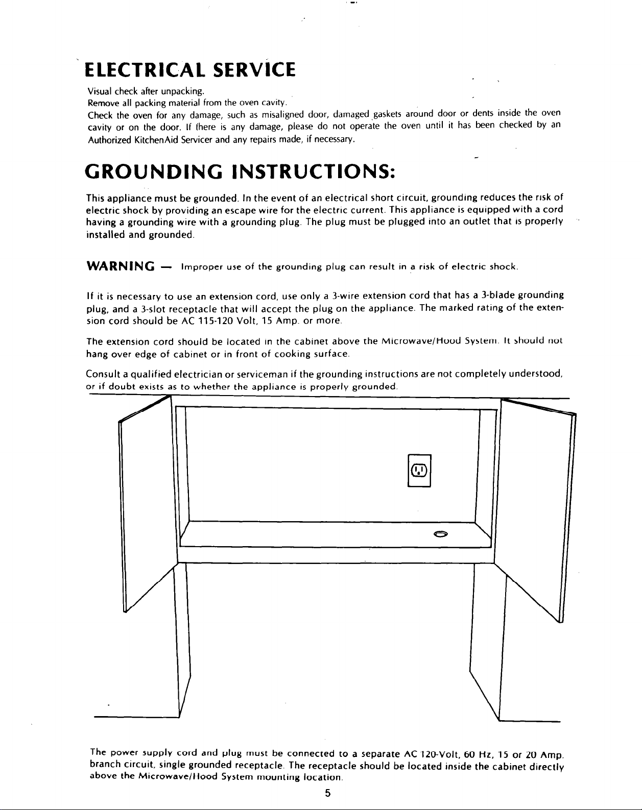
The power supply cord and plug must be connected to a separate AC 120-Volt, 60 Hz, 15 or 20 Amp.
branch circuit, single grounded receptacle. The receptacle should be located inside the cabinet directly
above the Microwave/Hood System mounting location.
5
HOOD EXHAUST DUCT
Outside ventilation requires HOOD EXHAUST DUCT. Read the following carefully.
EXHAUST CONNECTION: The hood exhaust has been designed to mate with a standard
3-x” x 10” rectangular duct.
If round duct is required, a rectangular-to-round transition adaptor must be used. DO not use
less than a 6” diameter duct.
REAR EXHAUST: If rear or horizontal exhaust is to be used, care should be taken to align ex-
haust with space between studs, or wall should be prepared at the time it is constructed by leav-
ing enough space between wall studs to accommodate exhaust.
MAXIMUM DUCT LENGTH: For satisfactory air movement, the total duct length.of 3-x” x 10”
rectangular or 6” diameter round duct should not exceed 140 feet.
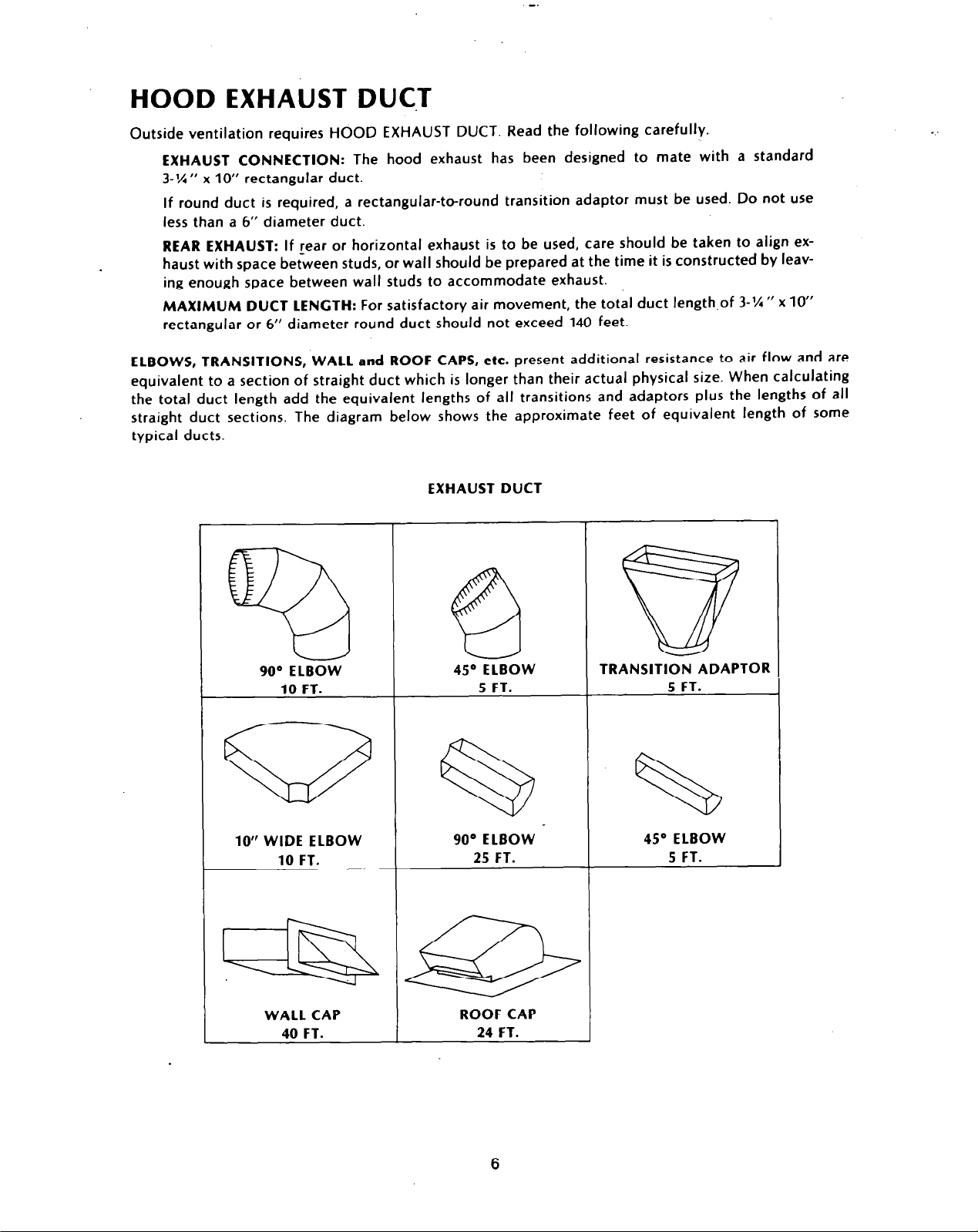
ELBOWS, TRANSITIONS, WALL and ROOF CAPS, etc. present additional resistance to air flow and are
equivalent to a section of straight duct which is longer than their actual physical size. When calculating
the total duct length add the equivalent lengths of all transitions and adaptors plus the lengths of all
straight duct sections. The diagram below shows the approximate feet of equivalent length of some
typical ducts.
EXHAUST DUCT
@a
90° ELBOW
10 FT.
10” WIDE ELBOW
10 FT.
WALL CAP
40 FT.
45O ELBOW
5 FT. 5 FT.
90’ ELBOW
25 FT.
ROOF CAP
24 FT.
TRANSITION ADAPTOR
I
I
4.5O ELBOW
5 FT.
I
1
6
 Loading...