

Page 1
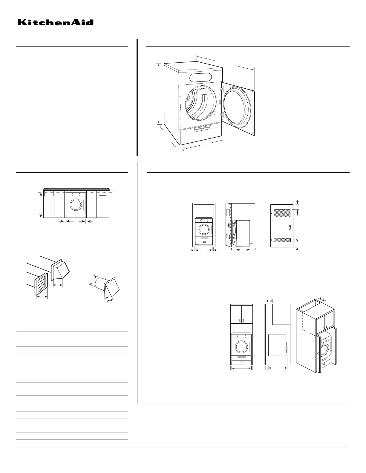
PRODUCT MODEL NUMBERS OVERALL DIMENSIONS
EXHAUST VENTING
KHGV01R
Because Whirlpool Corporation policy includes a continuous commitment to improve
our products, we reserve the right to change materials and specifications without notice.
Dimensions are for planning purposes only. For complete details, see Installation
Instructions packed with product. Specifications subject to change without notice.
Ref. 3957653
06-27-06
RECESSED AREA AND CLOSET INSTALLATION WITH OR WITHOUT PEDESTAL
UNDERCOUNTER INSTALLATION
A. Front view
B. Side view
C. Cabinet with vents
7"* (17.8 cm)
7"* (17.8 cm)
(12.7 cm)
33"
(83.8 cm)
1"
(2.5 cm)
5"
27"
(68.6 cm)
1"
(2.5 cm)
(2.5 cm)
1"
A
BC
For closet installation, with a door, the minimum ventilation openings in the top and
bottom of the door are required. Louvered doors with equivalent air ventilation openings
in the top and bottom are acceptable.
Dimensions shown are for minimum spacing.
Recommended hood style
Angled hood style is
acceptable.
• Select the route that will provide the straightest and most direct path outdoors.
• Plan the installation to use the fewest number of elbows and turns. Use the fewest
90° turns possible.
• Do not use vent runs longer than specified in vent length chart.
• Determine the number of elbows you will need.
Electrical: A 3 or 4 wire, single phase, 120/240
volt 60 Hz, AC only electrical supply (or 3 or 4 wire,
120/208 volt electrical supply, if specified on the
serial/rating plate) on a separate 30-amp circuit,
fused on both sides of the line. A time-delay fuse or
circuit breaker is recommended. Connect to an
individual branch circuit. Do not have a fuse in the
neutral or grounding circuit.
Exhaust venting: Exhaust your dryer to the
outside. Four inch diameter vent is required. Rigid
or flexible metal exhaust vent must be used. Do not
use plastic or metal foil vent. Exhaust outlet hood
must be at least 12 inches from the ground or any
object that may be in the path of the exhaust.
Recommended installation
spacing for cabinet installation
For cabinet installation, with a door,
the minimum ventilation openings in
the top are required.
*Includes door handle
**Includes feet extended 1" (2.5 cm)
NOTE: Most installations require a minimum
5" (12.7 cm) clearance behind the dryer for
the exhaust vent with elbow. See Installations
Instructions, “Venting Requirements.”
Pro Line®Front-Loading Gas Dryer
®
42"**
(106.7 cm)
33"*
(83.8 cm)
(68.6 cm)
27"
57"
(144.8 cm)
1"
(2.5 cm)
42" min.
(106.7 cm)
1"
(2.5 cm)
27"
(68.6 cm)
1"
(2.5 cm)
B
A
4"
(10.2 cm)
4"
(10.2 cm)
A. Louvered hood style
B. Box hood style
Vent system chart 1 - rigid metal vent only
Number of
90º turns
or elbows
0 Rigid metal 174 ft (53.0 m) 168 ft (51.2 m)
1 Rigid metal 164 ft (50.0 m) 158 ft (48.0 m)
2 Rigid metal 154 ft (46.9 m) 148 ft (45.1 m)
3 Rigid metal 145 ft (44.2 m) 139 ft (42.4 m)
4 Rigid metal 137 ft (41.8 m) 131 ft (39.9 m)
Vent system chart 2 - rigid metal vent used with a
maximum of 8 ft (2.4 m) flexible metal vent
Number of
90º turns
or elbows
0 Rigid metal 144 ft (43.9 m) 138 ft (42.1 m)
1 Rigid metal 134 ft (40.8 m) 128 ft (39.0 m)
2 Rigid metal 125 ft (38.1 m) 119 ft (36.3 m)
3 Rigid metal 117 ft (35.7 m) 111 ft (33.8 m)
Type of
vent
Type of
vent
Box or
louvered
hoods
Box or
louvered
hoods
4"
(10.2 cm)
Angled
hoods
Angled
hoods
2.5"
(6.4 cm)
3"*
(7.6 cm)
3"*
(7.6 cm)
C
1"
(2.5 cm)
(2.5 cm)
1"
1"
(2.5 cm)
(83.8 cm)
27"
(68.6 cm)
A
A. Front view
B. Side view - closet or confined area
C. Closet door with vents
33"
B
48 in.
(310 cm
24 in.
(155 cm
5"
(12.7 cm)
2
*
2
)
2
*
2
)
*Required spacing
 Loading...