

KitchenAid KGRS505X User Manual
30" (76.2 cm) Freestanding Gas Range
PRODUCT MODEL NUMBERS PRODUCT DIMENSIONS
KGRS505X
Gas supply line:
●
Provide a gas supply line of ³⁄₄" (1.9 cm) rigid pipe to the range
location. A smaller size pipe on longer runs may result in
insufficient gas supply. With LP gas, piping or tubing size can
be ¹⁄₂" (1.3 cm) minimum. Usually, LP gas suppliers determine
the size and materials used in the system.
NOTE: Pipe-joint compounds that resist the action of LP gas
must be used. Do not use TEFLON®†tape.
Flexible metal appliance connector:
●
If local codes permit, a new CSA design-certified, 4 to 5 ft
(122 to 152.4 cm) long, ¹⁄₂" (1.3 cm) or ³⁄₄" (1.9 cm) I.D.,
flexible metal appliance connector may be used for connecting
range to the gas supply line.
●
A ¹⁄₂" (1.3 cm) male pipe thread is needed for connection to
the female pipe threads of the inlet to the appliance pressure
regulator.
●
Do not kink or damage the flexible metal tubing when moving
the range.
●
Must include a shutoff valve:
The supply line must be equipped with a manual shutoff valve.
This valve should be located in the same room but external to
the range opening, such as an adjacent cabinet. It should be in a
location that allows ease of opening and closing. Do not block
access to shutoff valve. The valve is for turning on or shutting
off gas to the range.
Type of Gas
Natural gas:
This range is design-certified by CSA International for use with
Natural gas or, after proper conversion, for use with LP gas.
●
This range is factory set for use with Natural gas. See “Gas
Conversions” section. The model/serial rating plate located
behind the control panel has information on the types of gas
that can be used. If the types of gas listed do not include the
type of gas available, check with the local gas supplier.
LP gas conversion:
Conversion must be done by a qualified service technician.
No attempt shall be made to convert the appliance from the gas
specified on the model/serial rating plate for use with a different
gas without consulting the serving gas supplier. See “Gas
Conversions” section.
†®
TEFLON is a registered trademark of E.I. Du Pont De Nemours and Company.
Because Whirlpool Corporation policy includes a continuous commitment to improve
our products, we reserve the right to change materials and specifications without notice.
Dimensions are for planning purposes only. For complete details, see Installation
Instructions packed with product. Specifications subject to change without notice.
Ref. W10345639B
12/21/10
IMPORTANT: The range must be electrically grounded in accordance with local
codes and ordinances, or in the absence of local codes, with the National Electrical
Code, ANSI/NFPA 70 or Canadian Electrical Code, CSA C22.1.
If codes permit and a separate ground wire is used, it is recommended that a
qualified electrical installer determine that the ground path is adequate.
●
A 120 volt, 60 Hz., AC only, 15-amp fused, electrical circuit is required. A timedelay fuse or circuit breaker is also recommended. It is recommended that a
separate circuit serving only this range be provided.
●
Electronic ignition systems operate within wide voltage limits, but proper
grounding and polarity are necessary. Check that the outlet provides 120-volt
power and is correctly grounded.
g
Page 1 of 2
GAS SUPPLY REQUIREMENTS
ELECTRICAL REQUIREMENTS
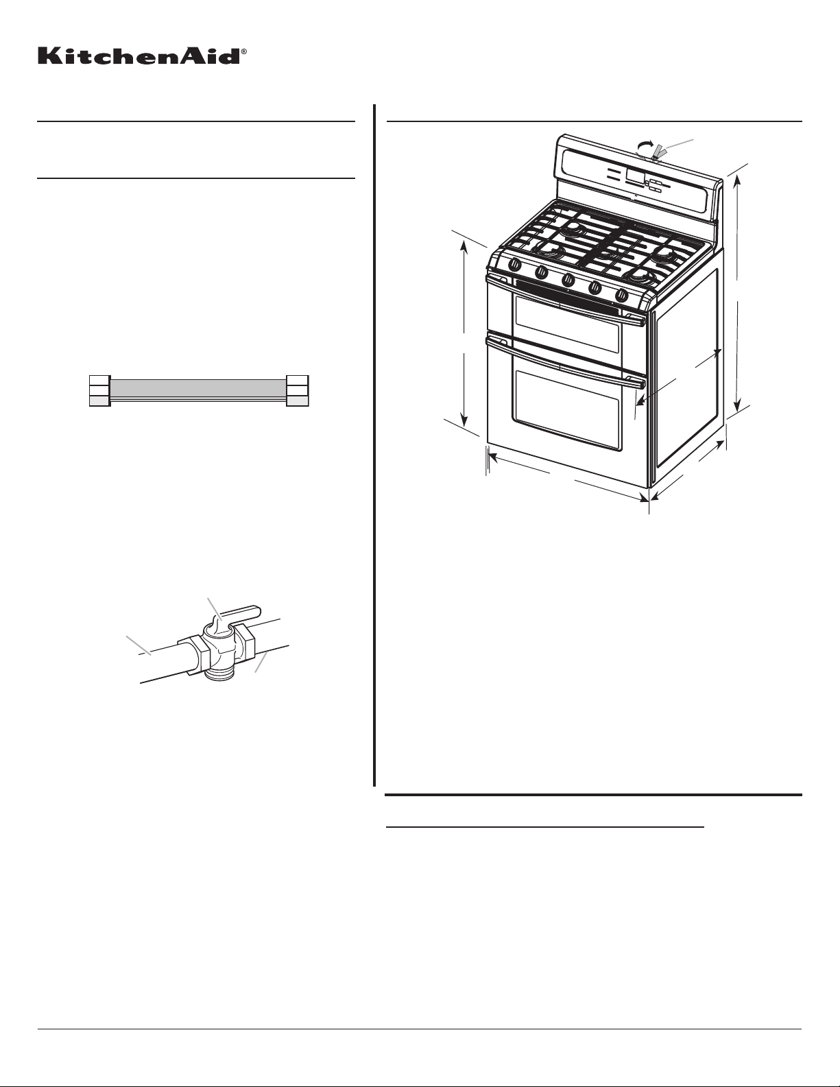
B
A
A
F
A. 35³⁄₄" ± ¹⁄₈" (90.8 ± 0.3 cm)
cooktop height (minimum)
with leveling legs screwed
all the way in
B. Model/serial/rating plates
(located behind the control
panel)*
B*
C**
D
E***
C. 47¹⁄₈" ± ¹⁄₈" (119.7 ± 0.3 cm)
overall height (minimum) with
leveling legs screwed all the
way in**
D. 28¹⁄₂" ± ¹⁄₄" (72.4 ± 0.6 cm)
depth with handle
E. 26¹⁄₈" to 27¼" ± ¹⁄₈"
(66.4 ± 0.3 cm)***
F. 29¹⁵⁄₁₆" ± ¹⁄₁₆" (76.0 ± 0.2 cm)
width
C
A. Gas supply line
B. Shutoff valve “open” position
C. To ran
e
*Model/serial/rating plates may be rotated up from behind the
control panel for viewing from the front of the range.
**Range can be raised approximately 1" (2.5 cm) by adjusting
the leveling legs.
***Excludes handle. Dimension given is from wall to front of oven
door and will vary based on electrical outlet receptacle
installation.
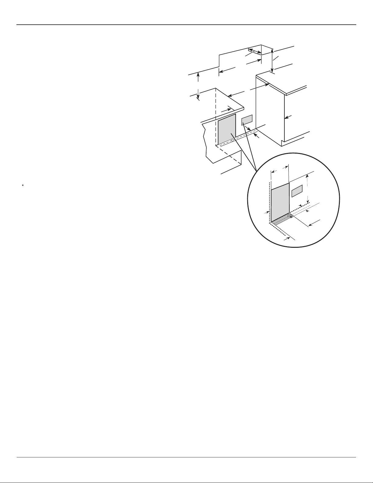
CABINET OPENING DIMENSIONS
Cabinet opening dimensions shown are for 25" (64.0 cm) countertop
depth, 24" (61.0 cm) base cabinet depth and 36" (91.4 cm) countertop
height.
IMPORTANT: If installing a range hood or microwave hood
combination above the range, follow the range hood or microwave
hood combination installation instructions for dimensional clearances
above the cooktop surface.
Range may be installed with zero clearance to combustible
construction at the rear and on the sides below the cooktop.
Because Whirlpool Corporation policy includes a continuous commitment to improve
our products, we reserve the right to change materials and specifications without notice.
Dimensions are for planning purposes only. For complete details, see Installation
Instructions packed with product. Specifications subject to change without notice.
Ref. W10345639B
12/21/10
Page 2 of 2
NOTE: 24" (61.0 cm) minimum when bottom of wood or metal cabinet
is covered by not less than ¹⁄₄" (0.64 cm) flame retardant millboard
covered with not less than No. 28 MSG sheet steel, 0.015" (0.4 mm)
stainless steel, 0.024" (0.6 mm) aluminum or 0.020" (0.5 mm) copper.
30" (76.2 cm) minimum clearance between the top of the cooking
platform and the bottom of an uncovered wood or metal cabinet.
A. 18" (45.7 cm) upper cabinet to countertop
B. 13" (33.0 cm) upper cabinet depth
C. 30" (76.2 cm) min. opening width
D. For minimum clearance to the top of the cooktop, see NOTE.
E. 30" (76.2 cm) min. opening width
F. 3" (7.6 cm) min. clearance from both sides of the range to the side
wall or other combustible material.
G. Cabinet door or hinges should not extend into the cutout.
H. 3" (7.6 cm) distance from wall
I. 1 " (3.8 cm) min. from right side cabinet
½
J. 8" (20.3 cm) width
K. 7" (17.8 cm) min. from floor
L. 2" (5.1 cm) min. from floor
B
D
C
A
E
F
J
I
K
L
G
H
8½"
(21.6 cm)
Drill on centerline 1¹⁄₄" (3.1 cm) from rear wall for gas supply
line.
**Gas lines must be installed within the shaded area to ensure
proper alignment of this oven with cabinets.
***Electrical plugs must be installed within the shaded area to
ensure proper alignment of this oven with cabinets.
1½"
(3.8 cm)
***
(35.6 cm)
2¼" (5.7 cm)
1¼"*
(3.1 cm)
8½" (21.6 cm)**
gas line location
14"
 Loading...