

KitchenAid KGCS166GWH1, KGCT055GWH0, KGCT055GBL0, KGCS166GWH0, KGCS166GSS1 Installation Guide
...Page 1
m [] []
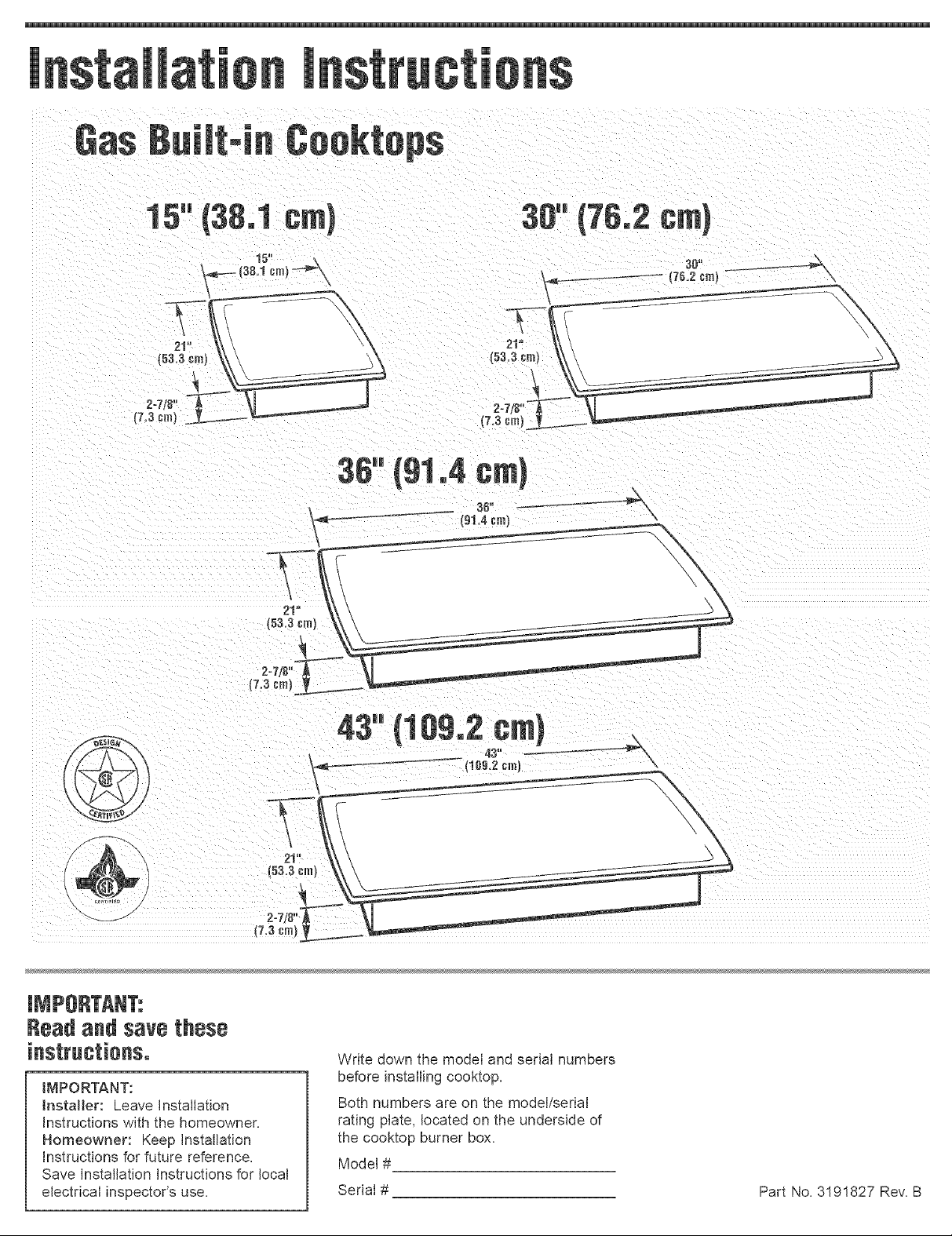
15" (38,1 cm}
278
30"(76.2cml
30" _ \
\
153,3cm)
36" (91,4 cml
36=,
- • {91,4cm_
Read and save these
IMPORTANT:
Installer: Leave Installation
Instructions with the homeowner,
Homeowner: Keep Installation
Instructions for future reference,
Save installation Instructions for local
electrical inspector's use,
43-(1o
{109,2_m_ \
Write down the model and serial numbers
before installing cooktop,
Both numbers are on the model/serial
rating plate, located on the underside of
the cooktop burner box,
Model #
Serial #
Part No, 3191827 Rev, B
Page 2
Befere youstart°°°
Your safety and the safety of
others are very important.
We have provided many important
safety messages in this manual and
on your appliance. Always read and
obey all safety messages.
This is the safety alert
symbol.
This symbol alerts you to
potential hazards that can kill or hurt
you and others.
All safety messages will follow the
safety alert symbol and either the
word "DANGER" or "WARNING".
These words mean:
You can be killed or seriously
injured if you don't immediately
follow instructions.
You can be killed or seriously
injured if you don't follow
instructions.
All safety messages will tell you
what the potential hazard is, tell you
how to reduce the chance of injury,
and tell you what can happen if the
instructions are not followed.
Important: Observe aH governing
codes and ordinances.
WARNING: _fthe
information in this manua_
is not followed exactly, a
fire or expRosion may result
causing property damage,
persona_ injury or death.
m Do not store or use
gasoline or other
flammable vapors and
_iquids in the vicinity of
this or any other
appliance.
WHAT TO DO _FYOU
SMELL GAS
o Do not try to _ight any
appliance.
o Do not touch any
eRectrica[ switch.
o Do not use any phone in
your building.
o _mmediatemy cam[your
gas supplier from a
neighbor's phone. Follow
the gas supp_[er's
instructions.
o _f you cannot reach your
gas supplier, call the fire
department.
_nstaHation and service
must be performed by a
quamified installer, service
agency or the gas
supplier.
Note: This cooktop is manufactured for
use with Natural gas. To convert to
LR/Propane gas, see instructions in the
Gas Conversion Kit provided in literature
package.
Proper gas suppJy connection must be
available. See "Gas supply requirements,"
Page 4.
Proper installation is your responsibility.
Have a qualified technician install this
cooktop.
Make sure you have everything
necessary for correct installation. It is the
responsibility of the installer to comply
with the installation clearances specified
on the model/serial rating plate. The
model/serial rating plate can be found on
the underside of the cooktop burner box.
Check location where cooktop will be
installed. The location should be away
from strong draft areas, such as windows,
doors and strong heating vents or fans.
Do not obstruct flow of combustion and
ventilation air.
All openings in the wall or floor where the
cooktop is to be installed must be sealed.
When installing a cooktop under existing
cabinets and the installation does not
meet the minimum cabinet clearances,
install a range hood above the cooktop to
avoid burn hazards.
Electdcat ground is required. See
"Electrical Requirements," Pages 4-5.
It is the customer's responsibility:
To contact a qualified electrical
instaJJer.
To assure that emectrical installation is
adequate and in conformance with
Nationam EJectrical Code, ANSJ/NFPA
70 -- latest edition*, or Canadian
Electrical Code, C22.1 -1982 and C22.2
No. 01982 (or Jatest edition)** and aH
local codes and ordinances.
Copies of the standards listed may be obtained
from:
*National Fire Protection Association
One Batterymarch Park
Quincy, Massachusetts 02269
** CSA Bntemational
6501 East Pmeasant Valley Rd.
C_eveJand, OH 44131-8575
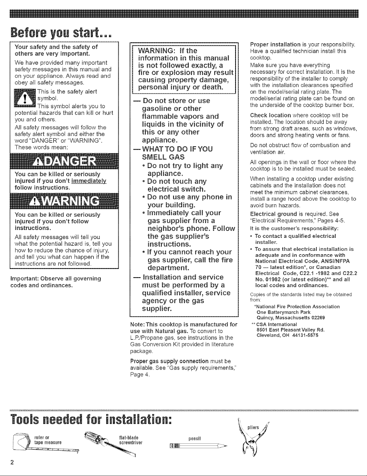
neededfer
pencil
Page 3
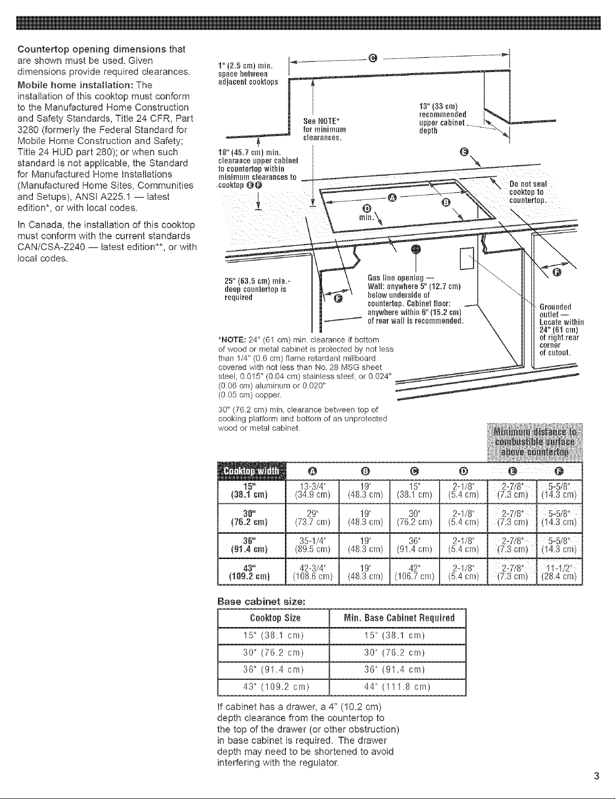
Countertop opening dimensions that
are shown must be used. Given
dimensions provide required clearances.
Mobite home installation: The
installation of this cooktop must conform
to the Manufactured Home Construction
and Safety Standards, Title 24 CFR, Part
3280 (formerly the Federal Standard for
Mobile Home Construction and Safety;
Title 24 HUD part 280); or when such
standard is not applicable, the Standard
for Manufactured Home Installations
(Manufactured Home Sites, Communities
and Setups), ANSI A225.1 -- latest
edition*, or with local codes.
in Canada, the installation of this cooktop
must conform with the current standards
CAN/CSA-Z240 -- latest edition**, or with
local codes.
1" (2.5 sin} min,
space between
adjacent cooktops
25" (63.5 crn) min,=
deep caantertop Us
required
*NOTE: 24" (61 cm) min. clearance if bottom
of wood or metal cabinet is protected by not tess
than 1/4" (0.6 cm) flame retardant mittboard
covered with not tess than No. 28 MSG sheet
steel, 0.015" (0.04 cm) stainless steel, or 0.024"
(0.06 cm) aluminum or 0.020"
(0.05 cm) copper.
30" (76.2 cm) min. clearance between top of
cooking platform and bottom of an unprotected
wood or metal cabinet.
Gas Hne apenUeg--
Walh anywhere 5""(12.7 crn)
below endersUdnof
couetertep, Cabinet floor:
anywhere within 6" (15,2 cm)
of rear wall is recommended,
,°
Do eat seal
Grounded
outlet--
Locatewithin
24"(61crn)
of right rear
career
of cutout,
e o @ @
15"
(38.1era)
38"
(76.2era)
Base cabinet size:
CooktopSize Min. BaseCabinetReqnired
15" (38.1 cm) 15" (38.1 crn)
30" (76.9 cm) 30" (78.2 crn)
36" (91.4 cm) 36" (91.4 crn)
43" (109.2 cm) 44" (111.8 crn)
If cabinet has a drawer, a 4" (10.2 cm)
depth clearance from the countertop to
the top of the drawer (or other obstruction)
in base cabinet is required. The drawer
depth may need to be shortened to avoid
interfering with the regulator.
13-3/4" 19" 15" 2-1/8"
(34.9crn) (48.3crn) (38.1crn) (5.4crn)
29"
(73.7crn}
35-1/4"
(89.5crn)
42-3/4"
(108.6crn)
19 _
(48.3cm)
19 _
(48.3crn)
19 _
(48.3cm)
30 '_
(78.2cm)
38 _
(91.4crn)
42"
(108.7cm)
2-1/8"
(5.4crn)
2-1/8"
(5.4crn)
2-1/8"
(5.4crn)
2-7/8" 5-5/8"
(7,3cm) (14,3cm)
5-5/8"
(7:3 cm) (14,3crn)
(7:3cm) (14,3cm)
1iq/2"
,7:3cm) (2&4cm)
Page 4

G8$ $U
Explosion Hazard
Use a new AGA or CSA approved
gas supply line.
Install a shut-off valve.
Securely tighten a_t gas
con nections.
If connected to LP, have a
qualified person make sure gas
pressure does not exceed 14"
water column.
Examples of a quamified person
include licensed heating
personnel, authorized gas
company personnel_ and
authorized service personnel
Failure to do so can result in
death, explosion, or fire.
Observe all governing codes and
ordinances,
Important: Cooktop must be connected
to a regulated gas supply,
A RThis installation must conform with
local codes and ordinances. In the
absence of local codes, installations must
conform with American National
Standard, National Fuel Gas Code ANSI
Z22&1 --latest edition** or CANI --
B149.1 or 2**.
BE Input ratings shown on the
model/serial rating plate are for elevations
up to 2,000 feet (610 m). For elevations
above 2,000 feet (610 m), ratings are
reduced at a rate of 4% for each 1,000
feet (305 m) above sea level.
EThe cooktop is equipped for use
with NATURAL gas. It is design-certified
by CSA International for NATURAL and
LR gases with appropriate conversion.
The model/serial rating plate, located on
the underside of the burner box, has
information on the type of gas that can be
used. Ifthis information does not agree
with the type of gas available, check with
the local gas supplier. See Page 2 for LR
gas conversion instructions.
mProvide a gas supply line of 3/4"
rigid pipe to the cooktop location. A
smaller size pipe on long runs may result
in insufficient gas supply. Pipe-joint
compounds, suitable for use with L.R gas,
must be used. With LR gas, piping or
tubing size can be 1/2" minimum. LR gas
suppliers usually determine the size and
materials used on the system.
E mIf local codes permit, a new AGA or
CSA design-certified, 4-5 foot (! .2-1.5 m)
long, 1/2" or 3/4" I.D., flexible metal
appliance connector is recommended for
connecting this cooktop to the gas supply
line. Do Not kink or damage the flexible
connector when moving the cooktop. The
pressure regulator has 3/8" female pipe
threads. You will need to determine the
fittings required, depending on the size of
your gas supply line, flexible metal
connector and shutoff valve.
shnt0ftvalve___
"open" pnniti0n _
tnc00kt0p.\__
/ _-_J gas supply
F line
EThe supply line shall be equipped
with an approved shutoff valve. This valve
should be located in the same room as
the cooktop and should be in a location
that allows ease of opening and closing.
Do Not block access to the shutoff valve.
The valve is for turning on or shutting off
gas to the appliance.
G.if rigid pipe __
is used as a gas
supply line, a combination of pipe Ill
fittings must be used to obtain an in-line
connection to the cooktop. All strains
must be removed from the supply and
fuel lines so cooktop will be level and in
line.
mThe regulator must be checked at
a minimum 1-inch (2.5 cm) water column
above the set pressure. The inlet pressure
to the regulator should be as follows for
operation and checking the regulator
setting:
NATURAL GAS:
Set pressure 4 inches (10.2 cm).
Supply pressure 7-14 inches (17.8 cm
to 35.5 cm) maximum.
L.P. GAS:
Minimum pressure 10 inches (28.4 cm).
Supply pressure 14 inches (38.8 cm).
mLine pressure testing:
Testing above 1t2 psi (3.8 kPa)
(14 inches (38.6 cm)) W.C. (gauge)
The cooktop and its individual shutoff
valve must be disconnected from the gas
supply piping system during any pressure
testing of that system at test pressures
greater than 1/2 psig (3.5kPa).
Testing below 1t2 psi (3.8 kPa)
(14 inches (38.6 cm)) WoC.(gauge) or
lower
The cooktop must be isolated from the
gas supply piping system by closing its
individual manual shutoff valve during any
pressure testing of the gas supply piping
system at test pressures equal to or less
than 1/2 psig (3.5 kPa).
Electrical Shock Hazard
Plug into a grounded 3-prong
outlet.
Do not remove ground prong.
Do not use an adapter.
Failure to follow these
instructions can result in death,
fire, or emectricamshock.
tf codes permit and a separate ground
wire is used, it is recommended that a
qualified electrician determine that the
ground path is adequate.
Check with a qualified electrician if
you are not sure whether the cooktop
is properly grounded.
Do Not ground to a gas pipe.
A 120-volt, 60-Hz, AC-only, 15-ampere,
fused electrical supply is required. A
time-delay fuse or circuit breaker is
recommended. It is recommended that a
separate circuit serving only this
appliance be provided.
Page 5

Electronicignitionsystemsoperatewithin
widevoltagelimits,butpropergroundand
polarityarenecessary.Inadditionto
checkingthattheoutletprovides120=volt
Nowstart,,,
With cooktop in kitchen.
powerandiscorrectlygrounded,the
outletmustbecheckedbyaqualified
electriciantoseeifitiswired with correct
polarity. A wiring diagram is provided in
the literature package.
Important: This range is equipped with
an electronic ignition system that will not
operate if plugged into an outlet that is
not properly polarized.
This appliance, when installed, must be
electrically grounded in accordance with
local codes or, in the absence of local
codes, with the current CSA standard
C22.1. Canadian Electrical Code Part 1.
Recommended ground method
For your personal safety, this cooktop
must be grounded. This cooktop is
equipped with a 3-prong ground plug. To
minimize possible shock hazard, the cord
must be plugged into a mating 3-prong
ground-type outlet, grounded in
accordance with the National Electrical
Code ANSI/NFPA 70 latest edition* or
Canadian Electrical Code (CSA)** -- and
local codes and ordinances. If a mating
outlet is not available, it is the personal
responsibility and obligation of the _
customer to have a properly polarized _- ->-_
a qualified electrician.
Numbers
correspond to steps. 6.
E Remove foam shipping blocks and
tape from cooktop. Untape power supply
cord.
strip
4E Glass Cooktops Only:
Remove foam strip from literature
package. Apply foam strip around bottom
of cooktop flush with edge.
and grounded, 3=prong outlet installed by
gr0und=type outlet
m Remove pressure regulator,
3=pr0ng hardware package, burner grates and
groundplug caps from shipping package.
3=pr0ngpolarized __
puv_er
supply cerd
Copies of the standards listed above may be
obtained from:
*National Fire Protection Association
One Batterymarch Park
Quincy, Massachusetts 02269
** CSA International
8501 East Pmeasant Valley Rd.
C_eveJand, OH 44131-8575
Lift entire cooktop up from cutout when
repositioning cooktop in countertop
opening to prevent scratching countertop.
3E Insert cooktop into countertop
opening. Center the cooktop inthe cutout.
Check that front edge of cooktop is
parallel to front edge of countertop. Check
that all required clearances are met. Use
a pencil to outline the rear of the cooktop
on the countertop. Remove the cooktop
from the cutout and place upside down
on a protected surface.
front of ¢ooktop
5m Remove two screws from left and
right bottom edges of burner box. Place
brackets on top of burner box. Position
brackets as shown and hand=tighten one
screw into each bracket.
m Reinsert the cooktop into
countertop opening. Check that cooktop
is parallel to front edge of countertop. Lift
entire cooktop to make adjustments.
Page 6

saaktap saantertap
/
' I
clamping screw
i
burner " bracket
box
pipe-joint compound made
for use with NATURAL and L.R gas. If
flexible metal connector is used, be
certain tubing isnot kinked.
"open" pasUfl
sbntaffvaleea__jnC)_
E_ectronic _gnition System m
initial lighting
Cooktop burners use electronic igniters in
place of standing pilots. When the
cooktop control knob is pushed in and
turned to the "LITE" position, the system
creates a spark to light the burner. This
sparking continues until the control knob
is turned to the desired setting.
E SCrews
Rotate brackets away from burner
box. Install second screw into each
bracket and tighten brackets to burner
box. Insert the 2-1/2" (6.4 cm) clamping
screws intothe brackets. Use a
screwdriver to tighten clamping screws
against the underside of countertop.
Do not overtighten screws.
mInstall the pressure regulator with
the arrow on the regulator pointing up
toward unit and in a position where you
can reach the access cap.
IMPORTANT: All connections must be
wrench-tightened. Do Not make
connections to the gas regulator too tight.
Making the connection too tight may
crack the regulator and cause a gas leak.
Do Not allow the regulator to turn on the
pipe when tightening fittings.
adapter
valve sampaund regulator
All connections must be wrench=
tightened.
E Assemble flexible metal connector
from the gas supply pipe to the pressure
regulator. Youwill need to determine the
fittings required, depending on the size of
your gas supply line, flexible metal
connector and shutoff valve.
3/8"
/ _ gas supply
EOpen shutoff valve in the gas
supply line. Wait a few minutes for gas to
move through the gas line.
m Leak testing of the appliance
shall be conducted according to the
following instructions:
Use a brush and liquid detergent to test
all gas connections for leaks. Bubbles
around connections will indicate a leak. If
a leak appears, shut off gas valve
controls and adjust connections. Then
check connections again. NEVER TEST
FOR GAS LEAKS WiTH A MATCH OR
OTHER FLAME. Clean all detergent
solution from cooktop.
3m Plug power supply cord into
grounded outlet.
Put burner caps on each burner
base. Place burner grates over burner
bases and caps.
Hne
O
O0
oo
"'9_/"7tH
1 5. Check operation of the cooktop
burners. Push in and turn each control
knob to "LITE" position. The flame should
light within 4 seconds. Do Not leave the
knob in the "LITE" position after
burner Hghtso
If burners do not light properly, turn
control knob to the "OFF" position. Check
that burner cap is in the proper position.
Check that power supply cord is plugged
in and that circuit breaker or house fuse
has not blown. Check that the shutoff
valve is in the "ON" position. Check
operation again. If a burner does not light
at this point, contact your Whirlpool dealer
for assistance.
m Push in and turn each control
knob to the '%0" (or simmer) setting. The
'%0" setting of each burner has been
factory set to the lowest setting available
to provide reliable reignition of the burner.
if it does not stay lit on the '%O"setting,
check '%O"setting as follows:
a. Turn control to "LiTE" until burner
ignites.
b. Quickly turn knob down to LOWEST
POSITION.
c. If burner goes out, readjust valve as
follows:
Remove the surface burner control knob.
Insert a flat-blade screwdriver into the
hollow valve stem and engage the slotted
screw. Flame size can be increased or
decreased by turning the screw. Adjust
flame until you can quickly turn knob from
"LITE" to LOWEST POSITION without
extinguishing the flame. Flame should be
as small as possible without going out.
Page 7

If ceoktep
net operate:
ing and
maintenance
_ Check that the circuit breaker is not
tripped or the house fuse blown.
[_ Check that the power supply cord is
plugged into the outlet.
[_ Check that gas valves are turned to
the "ON" position.
[_See Use and Care Guide for
troubleshooting list.
If youneed
tf you have questions about operating,
cteaning or maintaining your cooktop:
[_ Refer to Use and Care Guide.
[_ Call the Consumer Assistance
Center. Check your Use and Care
Guide for the number to call or call
the dealer from whom you
purchased this appliance. The dealer
is listed in the Yellow Pages of your
phone directory under "Appliances --
Household -- Major -- Service and
Repair."
Maintain the quality built into your
cooktop by calling an authorized
service company.
To obtain the name and number of the
authorized service company:
[_ Contact the dealer from whom you
purchased your cooktop; or
[_] Look in the Yellow Pages of your
telephone directory under
"Appliances -- Household --
Major -- Service and Repair;" or
[_ Call the Consumer Assistance
Center. The number is listed in your
Use and Care Guide.
When you call, you will need:
[_The cooktop model number.
[_] The cooktop serial number.
Both numbers are listed on the
model/serial rating plate located on the
underside of cooktop burner box.
If removing the cooktop is necessary for
cleaning or maintenance, shut off gas
supply. Disconnect the gas and electric
supply. Remove the mounting brackets on
the right and left side of burner box. After
disconnecting the gas and electric supply,
finish removing the unit for cleaning and
servicing. Reinstall in reverse order and
check gas connection for leaks.
Page 8

ROUND BLADE
CONNECT
,250 TERMINALS
(NOT USED)
(NOT USED)
ELK _i
SWITCHES ON VALVES
ELECTRtC CIRCUtT
CLOSED WHEN KNOB IS
ROTATED 55 ° TO 95 °
COUNTER CLOCKWISE
FROM OFF
THE POWER CORD ONTNIS APPLIANCE IS EQUIPPED
WITH ATHREE PRONGED (GROUNDING) PLUG WHICH
MATES WITN STANDARD THREE PRONGED (GROUNDrNG)
WALL RECEPTACLES
VALVE
SWITCHES
PLUG
NEUTRAL 5/15
WIDE BLADE
GRN OR GRNIY ii_GROUND
120VAC 60 Hz
I PHASE
15 OR 20 AMP
WHT
I
EC3 I
L....... I
iGNITOR
ELECTRODES _ .........
[
I
I
SPARK
MODULE
YEL OR
BRN
ROUND BLADE
CONNECT
,250 TERMINALS
ELK
SWITCHES ON VALVES
ELECTRIC CIRCUIT
CLOSED WHEN KNOB IS
ROTATED 55 ° TO 95 °
COUNTER CLOCKWISE
FROM OFF
THE POWER CORD ON THIS APPLIANCE IS EQUIPPED
WITH ATNREE PRONGED (GROUNDING) PLUGWNmCN
MATES WITH STANDARD THREE PRONGED (GROUNDING)
WALL RECEPTACLES
PLUG
120VAC 60 Hz
I PHASE
15 OR 20 AMP
VALVE
SWITCHES
GRN OR GRN/Y I I GROUND
IGNITOR
WNT
I I
I I
I__ <_ YELORBRN
ELECTRODES............1............
MODULE
(41 PLACES
Caution: Label aI_ wires prior to disconnection when servicing controls.
Wiring errors can cause improper and dangerous operation.
Verify proper operation after servicing.
GROUND
ROUND BLADE
CONNECT
.250 TERMINALS
BLK _
SWITCHES ON VALVES
ELECTRIC CIRCUIT
CLOSEDWHEN KNOB IS
ROTATED55°TO 95°
COUNTER CLOCKWISE
FROM OFF
Caution: Label aI_ wires prior to disconnection when servicing controM.
Wiring errors can cause improper and dangerous operation.
Verify proper operation after servicing.
THE POWER CORD ONTNIS APPLIANCE I$ EQUIPPED
WITH ATHREE PRONGED (GROUNDING) PLUG WHCN
MATES WITH STANDARD THREE PRONGED (GROUNDrNG)
WALL RECEPTACLES
VALVE
SWITCHES
PLUG
NEUTRAL5/16
WIDE BLADE
120VAC 60 Hz
I PHASE
15 OR 20 AMP
,GROUND
[
I
iGNITOR
ELECTRODES
WHT
ELK
SPARK
MODULE
: [3[]
_E_
Eli]
B,.......
BRN
YEL OR
(6) PLACES
±
Eli]
Caution: Label aII wires prior to disconnection when servicing controls.
WiNng errors can cause improper and dangerous operation.
Verify proper operation after servicing.
THE POWER CORD ON THIS APPUANCE _SEQUIPPED
W_TH A THREE PRONGED (GROUNDING) PLUG WHICH
MATES WITH STANDARD THREE PRONGED (GROUNDING)
WALL RECEPTACLES
GROUND
ROUND BLADE
FROM OFF
Caution: Label aH wires prior to disconnection when servicing controls.
Wiring errors can cause improper and dangerous operation.
Verify proper operation after servicing.
PLUG
_ _.................NEUTRAL 5/!5
_/ WIDE BLADE
/
\.L/
BLK
GRN OR GRN]Y
GRN OR GRN/Y
ELECTRODES
120VA¢ 60 Hz
15 OR 20 AMP
I PHASE
I,GROUND
If'GROUND
SPARK
±
Part No, 3191827 Rev, B
@2000Whirlpool Corporation Benton Harbor, Michigan 49022 Printed in U,S,A,
 Loading...