

KitchenAid KGCP484KSS05, KGCP482KSS05, KGCP483KSS05, KGCP463KSS05, KGCP462KSS05 Installation Instructions Manual
...
Kitchen/kid _
INSTALLATION INSTRUCTIONS
36" (91.4 CM) AND 48" (121.9 CM) COMMERCIAL STYLE
GAS COOKTOP
INSTRUCTIONS POUR D'INSTALLATION
'K
TABLE DE CUISSON A GAZ DE 36" (91,4 CM) ET
%
48" (121,9 CM) - MODELE COMMERCIAL
Table of Contents/Table des matieres ............................................................................. 2
iMPORTANT:
Save for local electrical inspector's use.
Installer: Leave installation instructions with the homeowner.
Homeowner: Keep installation instructions for future reference.
iMPORTANT :
,&,conserver pour consultation par I'inspecteur local des installations electriques.
Installateur : Remettre les instructions d'installation au proprietaire.
Proprietaire : Conserver les instructions d'installation pour reference ulterieure.
9759405
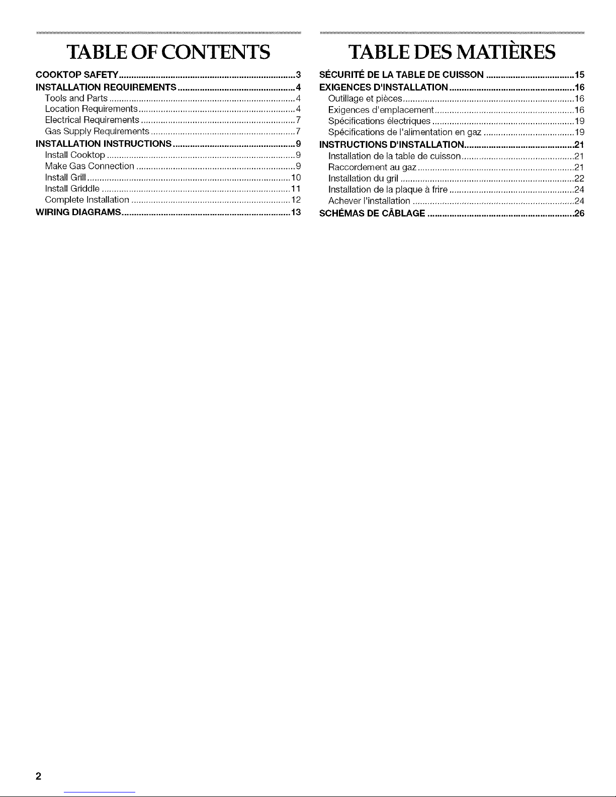
TABLE OF CONTENTS
COOKTOP SAFETY ........................................................................ 3
INSTALLATION REQUIREMENTS ................................................ 4
Tools and Parts ............................................................................ 4
Location Requirements ................................................................ 4
Electrical Requirements ............................................................... 7
Gas Supply Requirements ........................................................... 7
INSTALLATION INSTRUCTIONS .................................................. 9
Install Cooktop ............................................................................. 9
Make Gas Connection ................................................................. 9
Install Grill ................................................................................... 10
Install Griddle ............................................................................. 11
Complete Installation ................................................................. 12
WIRING DIAGRAMS ..................................................................... 13
TABLE DES MATIERES
SECURITE DE LA TABLE DE CUISSON .................................... 15
EXIGENCES D'INSTALLATION ................................................... 16
Outillage et pieces ...................................................................... 16
Exigences d'emplacement ......................................................... 16
Specifications electriques .......................................................... 19
Specifications de I'alimentation en gaz ..................................... 19
INSTRUCTIONS D'INSTALLATION ............................................. 21
Installation de la table de cuisson .............................................. 21
Raccordement au gaz ................................................................ 21
Installation du gril ....................................................................... 22
Installation de la plaque & frire ................................................... 24
Achever I'installation .................................................................. 24
SCHEMAS DE CABLAGE ............................................................ 26
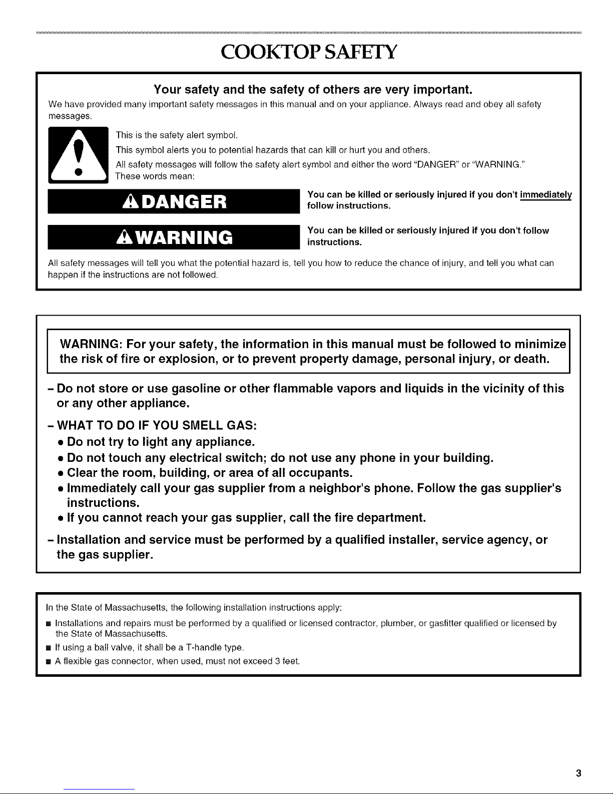
COOKTOP SAFETY
Your safety and the safety of others are very important.
We have provided many important safety messages in this manual and on your appliance. Always read and obey all safety
messages.
This is the safety alert symbol.
This symbol alerts you to potential hazards that can kill or hurt you and others.
All safety messages will follow the safety alert symbol and either the word "DANGER" or "WARNING."
These words mean:
You can be killed or seriously injured if you don't immediately
follow instructions.
You can be killed or seriously injured if you don't follow
instructions.
All safety messages will tell you what the potential hazard is, tell you how to reduce the chance of injury, and tell you what can
happen if the instructions are not followed.
i WARNING: For your safety, the information in this manual must be followed to minimize
the risk of fire or explosion, or to prevent property damage, personal injury, or death.
- Do not store or use gasoline or other flammable vapors and liquids in the vicinity of this
or any other appliance.
- WHAT TO DO IF YOU SMELL GAS:
• Do not try to light any appliance.
• Do not touch any electrical switch; do not use any phone in your building.
• Clear the room, building, or area of all occupants.
• Immediately call your gas supplier from a neighbor's phone. Follow the gas supplier's
instructions.
• If you cannot reach your gas supplier, call the fire department.
- Installation and service must be performed by a qualified installer, service agency, or
the gas supplier.
In the State of Massachusetts, the following installation instructions apply:
[] Installations and repairs must be performed by a qualified or licensed contractor, plumber, or gasfitter qualified or licensed by
the State of Massachusetts.
[] If using a ball valve, it shall be a T-handle type.
[] A flexible gas connector, when used, must not exceed 3 feet.
IN STALLATION REQUIREMENTS
Gather the required tools and parts before starting installation.
Read and follow the safety instructions provided with any tools
listed here.
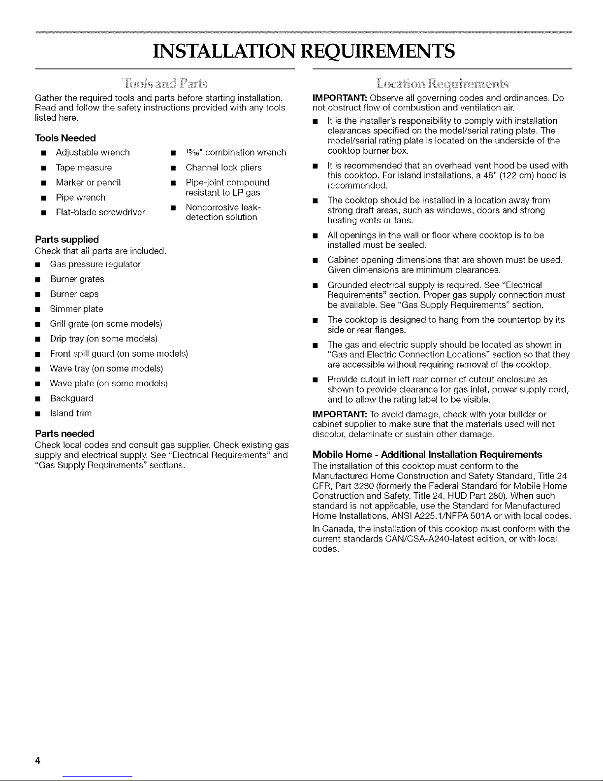
Tools Needed
• Adjustable wrench
• Tape measure
• Marker or pencil
• Pipe wrench
• Flat-blade screwdriver
• 1¾6"combination wrench
• Channel lock pliers
• Pipe-joint compound
resistant to LP gas
• Noncorrosive leak-
detection solution
Parts supplied
Check that all parts are included.
• Gas pressure regulator
• Burner grates
• Burner caps
• Simmer plate
• Grill grate (on some models)
• Drip tray (on some models)
• Front spill guard (on some models)
• Wave tray (on some models)
• Wave plate (on some models)
• Backguard
• Island trim
Parts needed
Check local codes and consult gas supplier. Check existing gas
supply and electrical supply. See "Electrical Requirements" and
"Gas Supply Requirements" sections.
? ....
IMPORTANT: Observe all governing codes and ordinances. Do
not obstruct flow of combustion and ventilation air.
It is the installer's responsibility to comply with installation
clearances specified on the model/serial rating plate. The
model/serial rating plate is located on the underside of the
cooktop burner box.
• It is recommended that an overhead vent hood be used with
this cooktop. For island installations, a 48" (122 cm) hood is
recommended.
• The cooktop should be installed in a location away from
strong draft areas, such as windows, doors and strong
heating vents or fans.
• All openings in the wall or floor where cooktop is to be
installed must be sealed.
• Cabinet opening dimensions that are shown must be used.
Given dimensions are minimum clearances.
• Grounded electrical supply is required. See "Electrical
Requirements" section. Proper gas supply connection must
be available. See "Gas Supply Requirements" section.
• The cooktop is designed to hang from the countertop by its
side or rear flanges.
• The gas and electric supply should be located as shown in
"Gas and Electric Connection Locations" section so that they
are accessible without requiring removal of the cooktop.
• Provide cutout in left rear corner of cutout enclosure as
shown to provide clearance for gas inlet, power supply cord,
and to allow the rating label to be visible.
IMPORTANT: To avoid damage, check with your builder or
cabinet supplier to make sure that the materials used will not
discolor, delaminate or sustain other damage.
Mobile Home - Additional Installation Requirements
The installation of this cooktop must conform to the
Manufactured Home Construction and Safety Standard, Title 24
CFR, Part 3280 (formerly the Federal Standard for Mobile Home
Construction and Safety, Title 24, HUD Part 280). When such
standard is not applicable, use the Standard for Manufactured
Home Installations, ANSI A225.1/NFPA 501A or with local codes.
In Canada, the installation of this cooktop must conform with the
current standards CAN/CSA-A240-1atest edition, or with local
codes.
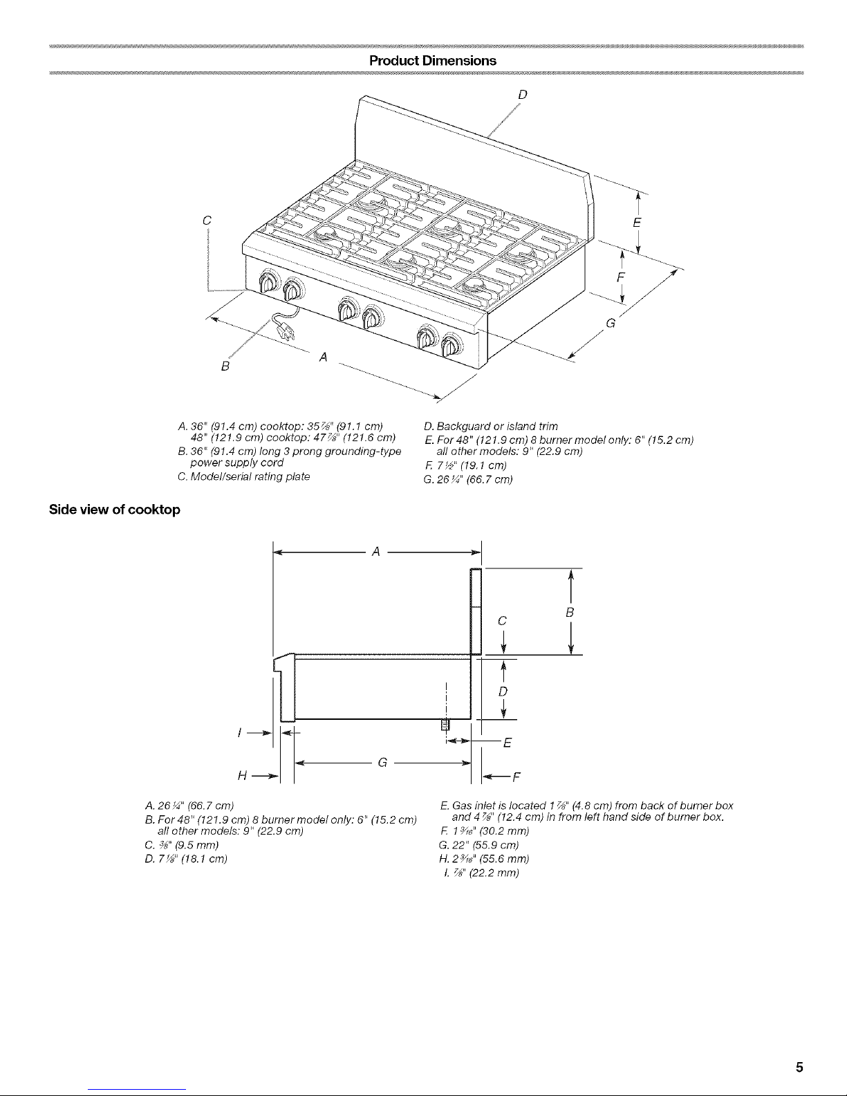
Product Dimensions
D
A, 36" (91.4 cm) cooktop: 35_" (91.1 cm)
48" (121.9 cm) cooktop: 47_" (121.6 cm)
B, 36" (91.4 cm) long 3 prong grounding-type
power supply cord
C, Model/serial rating plate
D. Backguard or island trim
E.For48" (121.9 cm) 8 burner model only." 6" (15.2 cm)
all ether models: 9" (22.9 cm)
F. 7½" (19.! cm)
G. 26 _" (66, 7 cm)
Side view of cooktop
< A
/
G
H-_
A. 26¼" (66,7cm)
B. For 48" (121,9 cm) 8 burner model only: 6" (15,2 cm)
all other models: 9" (22.9 cm)
C. ,_" (9.5 mm)
D. 7_" (18.! cm)
i c B
f
i D
I
i_--_ m eE F
E. Gas inlet is located 1_" (4.8 cm) from back of bumer box
and 4 _" (12.4 cm) in from left hand side of burner box,
F. ! _6" (30.2 mm)
G, 22" (55.9 cm)
H. 2_6" (55,6 mm)
L _" (22.2 mm)
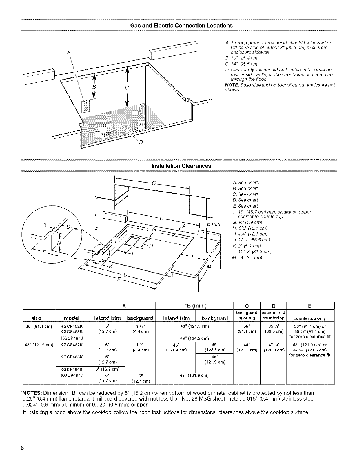
Gas and Electric Connection Locations
A. 3 prong ground-type outlet should be located on
left hand side of cutout 8" (20.3 cm) max. from
enclosure sidewall
B. 10" (25.4 cm)
C. 14" (35.6 cm)
D. Gas supply line should be located in this area on
rear or side walls, or the supply line can come up
through the floor.
NOTE: Solid side and bottom of cutout enclosure not
shown.
D
Installation Clearances
A. See chart.
B. See chart.
C. See chart
D. See chart
E.See chart
F. 18" (45.7 cm) min. clearance upper
cabinet to countertop
G. _" (1.9 cm)
H. 6_" (!6. ! cm)
L4¾" (12.1 cm)
J. 22 _" (56.5 cm)
K. 2" (5.1cm)
L. 12_6" (31.3 cm)
M. 24" (6! cm)
*B (rain.) E
size island trim backguard countertop only
38" (91.4 cm) 48" (121.9 cm)
48" (121.9 cm)
model
KGCP462K
KGCP483K
KGCP467J
KGCP482K
KGCP483K
KGCP484K
KGCP487J
island trim
5"
(12.7 cm)
6"
(15.2 cm)
5"
(12.7 cm)
6" (15.2 cm)
5"
(12.7 cm)
A
backguard
13/4"
(4.4 cm)
1 3/4"
(4.4 cm)
5 II
(12,7 crn)
49" (124.5 cm)
48" 49"
(121.9 cm) (124.5 cm)
48"
(121.9 cm)
48" (121.9 cm)
C
backguard
opening
36"
(91.4 cm)
48"
(121.9 cm)
D
cabinet and
countertop
351/O
(89.5 crn)
47 1/O
(120.0 cm)
36" (91.4 cm) or
35 7/8" (91.1 crn)
for zero clearance fit
48" (121.9 cm) or
47%" (121.8 cm)
for zero clearance fit
*NOTES: Dimension "B" can be reduced by 6" (15.2 cm) when bottom of wood or metal cabinet is protected by not less than
0.25" (6.4 mm) flame retardant millboard covered with not less than No. 28 MSG sheet metal, 0.015" (0.4 mm) stainless steel,
0.024" (0.6 mm) aluminum or 0.020" (0.5 mm) copper.
If installing a hood above the cooktop, follow the hood instructions for dimensional clearances above the cooktop surface.
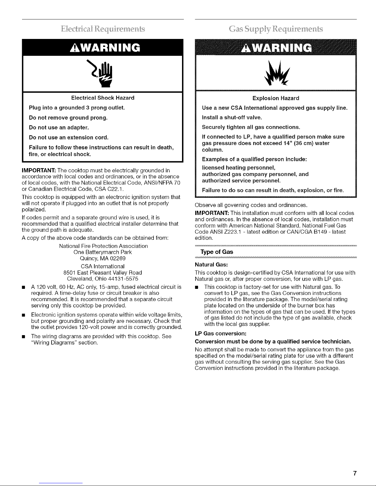
Electrical Shock Hazard
Plug into a grounded 3 prong outlet.
Do not remove ground prong.
Do not use an adapter.
Do not use an extension cord.
Failure to follow these instructions can result in death,
fire, or electrical shock.
IMPORTANT: The cooktop must be electrically grounded in
accordance with local codes and ordinances, or in the absence
of local codes, with the National Electrical Code, ANSI/NFPA 70
or Canadian Electrical Code, CSA C22.1.
This cooktop is equipped with an electronic ignition system that
will not operate if plugged into an outlet that is not properly
polarized.
If codes permit and a separate ground wire is used, it is
recommended that a qualified electrical installer determine that
the ground path is adequate.
A copy of the above code standards can be obtained from:
National Fire Protection Association
One Batterymarch Park
Quincy, MA 02269
CSA International
8501 East Pleasant Valley Road
Cleveland, Ohio 44131-5575
• A 120 volt, 60 Hz, AC only, 15-amp, fused electrical circuit is
required. A time-delay fuse or circuit breaker is also
recommended. It is recommended that a separate circuit
serving only this cooktop be provided.
• Electronic ignition systems operate within wide voltage limits,
but proper grounding and polarity are necessary. Check that
the outlet provides 120-volt power and is correctly grounded.
• The wiring diagrams are provided with this cooktop. See
"Wiring Diagrams" section.
Explosion Hazard
Use a new CSA international approved gas supply line.
install a shut-off valve.
Securely tighten all gas connections.
if connected to LP, have a qualified person make sure
gas pressure does not exceed 14" (36 cm) water
column.
Examples of a qualified person include:
licensed heating personnel,
authorized gas company personnel, and
authorized service personnel,
Failure to do so can result in death, explosion, or fire.
Observe all governing codes and ordinances.
IMPORTANT: This installation must conform with all local codes
and ordinances. In the absence of local codes, installation must
conform with American National Standard, National Fuel Gas
Code ANSI Z223.1 - latest edition or CAN/CGA B149 - latest
edition.
Type of Gas
Natural Gas:
This cooktop is design-certified by CSA International for use with
Natural gas or, after proper conversion, for use with LP gas.
• This cooktop is factory-set for use with Natural gas. To
convert to LP gas, see the Gas Conversion instructions
provided in the literature package. The model/serial rating
plate located on the underside of the burner box has
information on the types of gas that can be used. If the types
of gas listed do not include the type of gas available, check
with the local gas supplier.
LP Gas conversion:
Conversion must be done by a qualified service technician.
No attempt shall be made to convert the appliance from the gas
specified on the model/serial rating plate for use with a different
gas without consulting the serving gas supplier. See the Gas
Conversion instructions provided in the literature package.
Gas Supply Line
Provide a gas supply line of 3/4"(1.9 cm) rigid pipe to the
cooktop location. A smaller size pipe on longer runs may
result in insufficient gas supply. Pipe-joint compounds that
resist the action of LP gas must be used. Do not use
TEFLON _ tape. With LP gas, piping or tubing size can be 1/2"
minimum. Usually, LP gas suppliers determine the size and
materials used in the system.
Flexible metal appliance connector:
• If local codes permit, use a %" flexible stainless steel
tubing gas connector, designed by CSA to connect the
cooktop to the rigid gas supply line.
• A r/2" (1.3 cm) male pipe thread is needed for connection
to the female pipe threads of the inlet to the appliance
pressure regulator.
• Do not kink or damage the flexible metal tubing when
moving the cooktop.
Rigid pipe connection:
The rigid pipe connection requires a combination of pipe
fittings to obtain an in-line connection to the cooktop. The
rigid pipe must be level with the cooktop connection. All
strains must be removed from the supply and fuel lines so
cooktop will be level and in line.
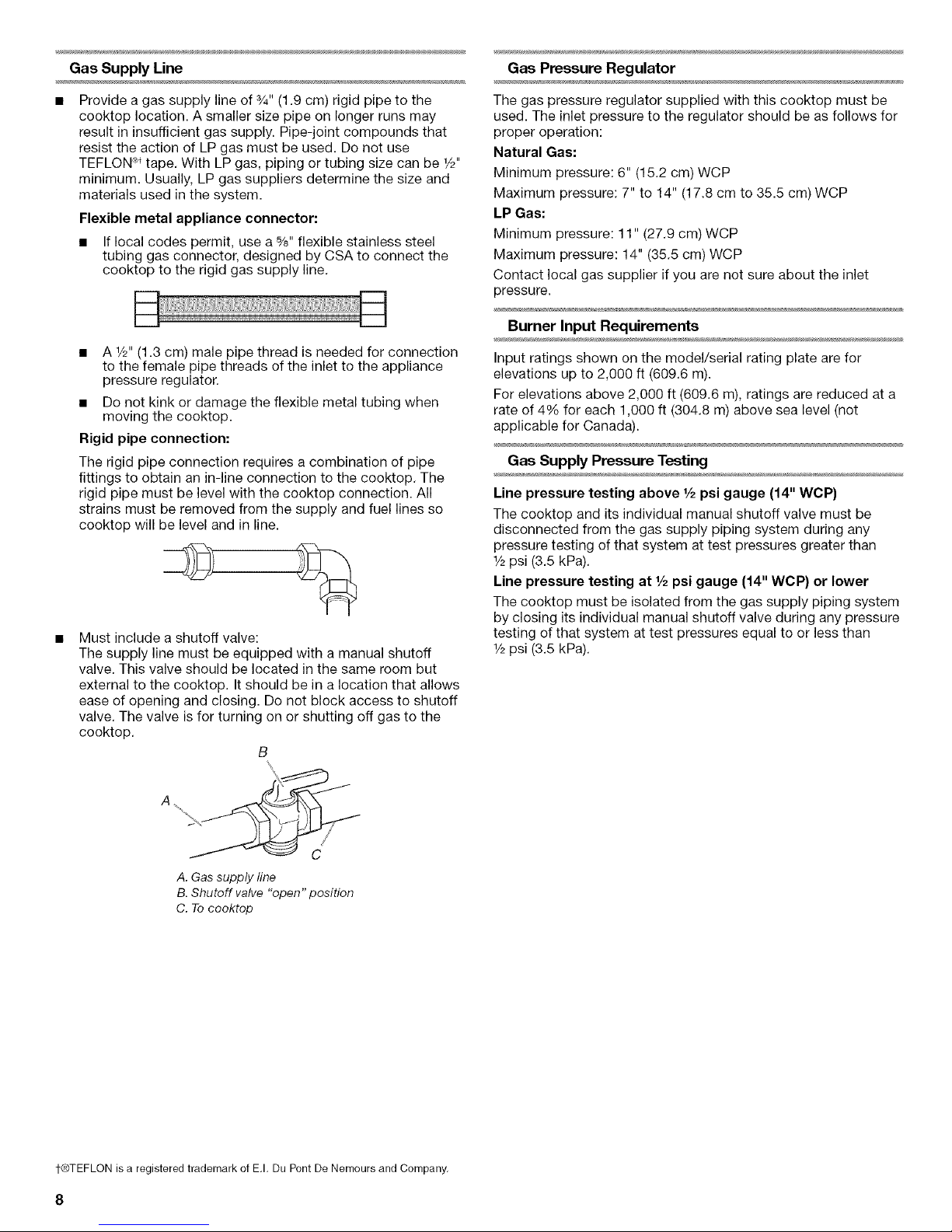
Must include a shutoff valve:
The supply line must be equipped with a manual shutoff
valve. This valve should be located in the same room but
external to the cooktop. It should be in a location that allows
ease of opening and closing. Do not block access to shutoff
valve. The valve is for turning on or shutting off gas to the
cooktop.
B
\
A. Gas supply line
B. Shutoff valve "open" position
C. To cooktop
Gas Pressure Regulator
The gas pressure regulator supplied with this cooktop must be
used. The inlet pressure to the regulator should be as follows for
proper operation:
Natural Gas:
Minimum pressure: 6" (15.2 cm) WCP
Maximum pressure: 7" to 14" (17.8 cm to 35.5 cm) WCP
LP Gas:
Minimum pressure: 11" (27.9 cm) WCP
Maximum pressure: 14" (35.5 cm) WCP
Contact local gas supplier if you are not sure about the inlet
pressure.
Burner Input Requirements
Input ratings shown on the model/serial rating plate are for
elevations up to 2,000 ft (609.6 m).
For elevations above 2,000 ft (609.6 m), ratings are reduced at a
rate of 4% for each 1,000 ft (304.8 m) above sea level (not
applicable for Canada).
Gas Supply Pressure Testing
Line pressure testing above 1/2psi gauge (14" WCP)
The cooktop and its individual manual shutoff valve must be
disconnected from the gas supply piping system during any
pressure testing of that system at test pressures greater than
r/2psi (3.5 kPa).
Line pressure testing at 1/2psi gauge (14" WCP) or lower
The cooktop must be isolated from the gas supply piping system
by closing its individual manual shutoff valve during any pressure
testing of that system at test pressures equal to or less than
r/2psi (3.5 kPa).
1-®TEFLON is a registered trademark of E.I. Du Pont De Nemours and Company.
INSTALLATION INSTRUCTIONS
Excessive Weight Hazard
Use two or more people to move and install cooktop.
Failure to do so can result in back or other injury.
Write down the model and serial numbers before installing the
cooktop. Both numbers are located on the left front underside of
the burner box.
Unpack the parts supplied with your cooktop. The parts shipped
with the cooktop depend on your model ordered. See "Tools and
Parts" section for a complete list parts supplied with your
cooktop.
Decide on final location for the cooktop.
The pressure regulator and flexible stainless steel gas supply line
connector can be assembled to the cooktop now or after the
cooktop is installed in the cutout. See "Make Gas Connection"
section.
To Install Backguard or Island Trim
Attach the backguard or island trim as required for your
installation. Attachment screws are in the literature package.
Backguard
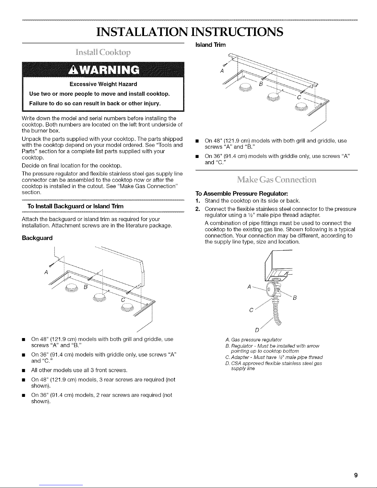
Island Trim
A
On 48" (121.9 cm) models with both grill and griddle, use
screws "A" and "B."
On 36" (91.4 cm) models with griddle only, use screws "A"
and "C."
! ........
To Assemble Pressure Regulator:
1. Stand the cooktop on its side or back.
2. Connect the flexible stainless steel connector to the pressure
regulator using a W' male pipe thread adapter.
A combination of pipe fittings must be used to connect the
cooktop to the existing gas line. Shown following is a typical
connection. Your connection may be different, according to
the supply line type, size and location.
A
• On 48" (121.9 cm) models with both grill and griddle, use
screws "A" and "B."
• On 36" (91.4 cm) models with griddle only, use screws "A"
and "C."
• All other models use all 3 front screws.
• On 48" (121.9 cm) models, 3 rear screws are required (not
shown).
• On 36" (91.4 cm) models, 2 rear screws are required (not
shown).
D
A. Gas pressure regulator
B. Regulator - Must be installed with arrow
pointing up to cooktop bottom
C. Adapter - Must have ½" male pipe thread
D. CSA approved flexible stainless steel gas
supply line
 Loading...