

KitchenAid KGCP484KSS04 Installation Guide
I " I i
(91.4cm) (1 .9 cm)
Style Cooktop
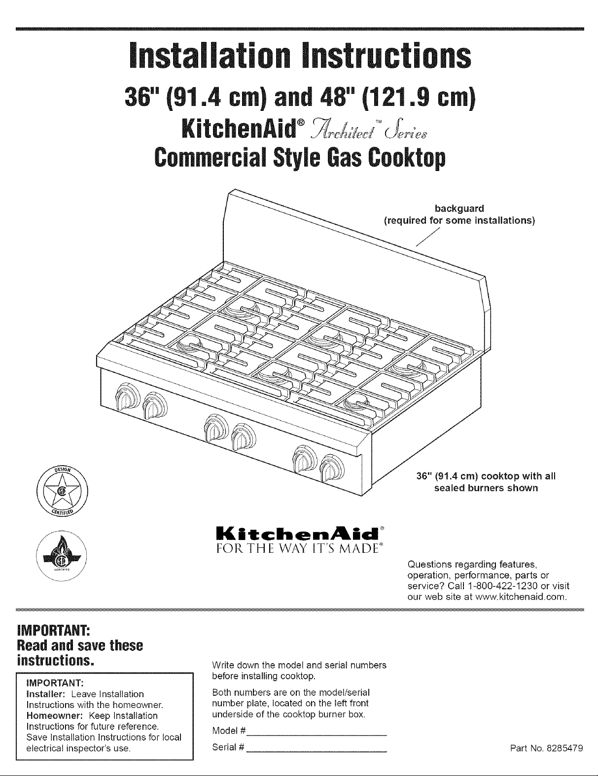
(required for some installations)
backguard
/
IMPORTANT:
Read and save these
instructions.
IMPORTANT:
Installer: Leave Installation
Instructions with the homeowner.
Homeowner: Keep Installation
Instructions for future reference.
Save Installation Instructions for local
electrical inspector's use.
KJtchenAJd _
FOR TH E WAY IT'S MADE _'
Write down the model and serial numbers
before installing cooktop.
Both numbers are on the model/serial
number plate, located on the leftfront
underside of the cooktop burner box.
Model #
Serial #
36" (91.4 cm) cooktop with all
sealed burners shown
Questions regarding features,
operation, performance, parts or
service? Call 1-800-422-1230 or visit
our web site at www.kitchenaid.com.
Part No. 8285479
Beforeyoustart,,,
Your safety and the safety of
others are very important.
We have provided many important
safety messages in this manual and
on your appliance. Always read and
obey all safety messages.
This is the safety alert
symbol.
This symbol alerts you to
potential hazards that can kill or hurt
you and others.
All safety messages will follow the
safety alert symbol and either the
word "DANGER" or "WARNING".
These words mean:
You can be killed or seriously
injured if you don't immediately
follow instructions.
You can be killed or seriously
injured if you don't follow
instructions.
All safety messages will tell you
what the potential hazard is, tell you
how to reduce the chance of injury,
and tell you what can happen if the
instructions are not followed.
Important: Observe all governing
codes and ordinances.
In the State of Massachusetts, the
following installation instructions
apply:
* Installations and repairs must be
performed by a qualified or licensed
contractor, plumber, or gasfitter
qualified or licensed by the State of
Massachusetts.
* If using a ball valve, it shall be a
T-handle type.
* A flexible gas connector, when used,
must not exceed 3 feet.
WARNING: If the
information in this manual
is not followed exactly, a
fire or explosion may result
causing property damage,
personal injury or death.
m Do not store or use
gasoline or other
flammable vapors and
liquids in the vicinity of
this or any other
appliance.
mWHATTO DO IFYOU
SMELL GAS
* Do not try to light any
appliance.
* Do not touch any
electrical switch.
* Do not use any phone in
your building.
* Immediately call your
gas supplier from a
neighbor's phone. Follow
the gas supplier's
instructions.
* If you cannot reach your
gas supplier, call the fire
department.
-- Installation and service
must be performed by a
qualified installer, service
agency or the gas
supplier.
The California Safe Drinking Water and
Toxic Enforcement Act requires the
Governor of California to publish a list of
substances known to the State of
California to cause cancer, birth defects,
or other reproductive harm, and requires
businesses to warn of potential exposure
to such substances.
WARNING: This product contains a
chemical known to the State of California
to cause cancer, birth defects, or other
reproductive harm.
This appliance can cause low-level
exposure to some of the substances
listed, including benzene, crystalline silica,
carbon monoxide, toluene, and soot.
NOTE: This cooktop is manufactured for
use with Natural gas. To convert to
L.P./Propane gas, see the Gas
Conversion instructions provided in
literaturepackage.
Proper gas supply connection must be
available. See "Gas supply requirements."
Proper installation is your responsibility.
Have a qualified technician install this
cooktop.
Make sure you have everything
necessary for correct installation. It is the
responsibility of the installer to comply
with the installation clearances specified
on the model/serial rating plate. The
model/serial rating plate can be found on
the underside of the cooktop burner box.
it is recommended that an overhead vent
hood be used with this cooktop. For
island installations, a 48" (122 cm) hood
is recommended.
Check location where cooktop will be
installed. The location should be away
from strong draft areas, such as windows,
doors and strong heating vents or fans.
Do not obstruct flow of combustion and
ventilation air.
All openings in the wall or floor where the
cooktop is to be installed must be sealed.
Electrical ground is required. See
"Electrical Requirements."
it is the customer's responsibility:
• To contact a qualified electrical
installer.
To assure that electrical installation is
adequate and in conformance with
National Electrical Code, ANSI/NFPA
70 -- latest edition*, or Canadian
Electrical Code, C22.1 -1982 and C22.2
No. 01982 (or latest edition)** and all
local codes and ordinances.
Copies of the standards listed may be obtained
from:
* Nationa! Fire Protection Association
One Batterymarch Park
Quincy, Massachusetts 02269
** CSA international
8501 East Pleasant Valley Rd.
Cleveland, Ohio 44131-5578

Product Dimensions
36" (91.4 cm) cooktop with all
sealed burners shown
backguard/shown)
or island trim (see P.4.and 7)
for 48" (121.0 sin)
8 burner model only:
6" (15.2 sin)
all other models:
(22.0sm)
36"(91.4sin)lung
3-prongground-
typepower
supplysord
36" (01.4 cm) cooktop:35-710"(91.1 cm)
40" (121.9 cm) cooktop:47-718" (121.6 sin)
"_ 26-1/4" (66.7 sin)
7/8" _
(22.2 ram) I J
2-3116"-........._-I j.._
(55.6 ram)
22" (55.9 sin)
j for 48" (121.9 sin)
3/8" 6" (15.2 sin)
(9.5 ram) all other models:
7-1/8"
8 burner model only:
(18.1sin)
I
-'4--
I
gas inlet islocated 1-7/8" (4.8 cm)Iron]
-- back of burner box and
4-718" (12,4 cm) in from L.H. side of
burner,box
_,_.-..-1-3/'16'
(30.2 ram)
9"(22,9 sin)
side view of cooktep
Cabinet and Cutout imensions
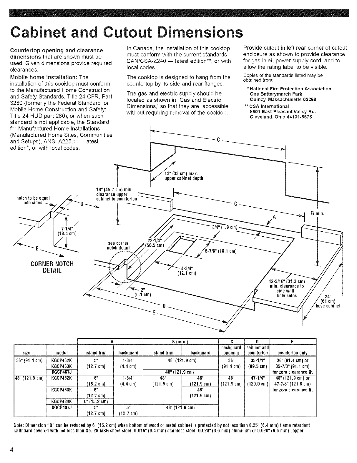
Countertop opening and clearance
dimensions that are shown must be
used. Given dimensions provide required
clearances.
Mobile home installation: The
installation of this cooktop must conform
to the Manufactured Home Construction
and Safety Standards, Title 24 CFR, Part
3280 (formerly the Federal Standard for
Mobile Home Construction and Safety;
Title 24 HUD part 280); or when such
standard is not applicable, the Standard
for Manufactured Home installations
(Manufactured Home Sites, Communities
and Setups), ANSI A225.1 --latest
edition*, or with local codes.
18" (45.7 cm) min.
notchtobeequal
bothsides.
clearance upper
cabinet to countertap
In Canada, the installation of this cooktop
must conform with the current standards
CAN/CSA-Z240 -- latest edition**, or with
local codes.
The cooktop is designed to hang from the
countertop by its side and rear flanges.
The gas and electric supply should be
located as shown in "Gas and Electric
Dimensions," so that they are accessible
without requiring removal of the cooktop.
Provide cutout in left rear corner of cutout
enclosure as shown to provide clearance
for gas inlet, power supply cord, and to
allow the rating label to be visible.
Copies of the standards listed maybe
obtained from:
* National Fire Protection Association
One Batterymarch Park
Quincy, Massachusetts 02269
** CSA International
8501 East Pleasant Valley Rd.
Cleveland, Ohio 44131-5575
CORNERNOTCH
size
36" (91.4 cm)
40" (121.0 cm)
(18.4 cm)
DETAIL
model
K6CP462K
KGCP463K
KGCP467J
KGCP482K
KGCP483K
KGCP484K
KGCP487J
7-1/4"
island trim
5"
(12.7 ¢m)
6II
(15.2cm)
5"
(12.7 cm)
6" (15.2 cm)
5H
(12.7 cm)
see corner
notch detail
A
backgoard
1-3/4"
(4.4 cm)
1-3/4"
(4.4 ¢m)
(12.7 cm)
"3/4"(1.9 cm)
22-1/4"
i(56.5cm)
6-7/8" (16.1 cm)
(12.1 cm)
12-5/10" (31.3 cm)
rain. clearance to
side wall -
both sides
(61cm)
basecabinet
B(_in.)
island trim backguard
48" (121.9 cm)
C
backguard
opening
36"
(91.4 cm)
48" (121.9cm)
48" 48"
(121.8¢m) (121.9cm)
40"
(121,9 cm)
48"
(121.9cm)
5 II
48" (121.9 cm)
D
cabinetand
countertop
35-1/4"
(89.5 cm)
47-1/4"
(120.0cm)
countertoponly
36" (01.4 cm) or
35-7/8" (91.1 cm)
for zero clearance tit
48" (121.0 cm) or
47-7/8" (121.6 cm)
tar zero clearance tit
Note:Dimension"g" canbereducedby5" (15.2 cm)whenbottomof woodor metal cabinetisprotectedbynotlessthan0.25"(6,4 ram)flameretardant
millbeardcoveredwithnotless thanNo. 28MSGsheetsteel,0.015"(0.4 ram)stainlesssteel,0.024"(0.5 mm)aluminumor 0.020"(8.5 ram)copper.
Gas and Electric
Gassupply
Dimensions
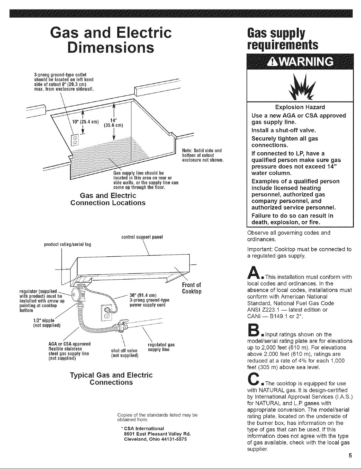
3-prongground-typeoutlet
shouldbelocatedonlefthand
sideofcutout8" 20.3 cm)
max. from eflc osuresdewa .
Gas and Electric
Connection Locations
Gassupplylineshouldhe
locatedinthisareaonrearor
sidewalls,orthesupplylinecan
comeupthroughthefloor.
Note: Solid side and
bottom ofcutout
enclosure net shown,
requirements
Explosion Hazard
Use a new AGA or CSA approved
gas supply line.
Install a shut-off valve.
Securely tighten all gas
connections.
If connected to LP, have a
qualified person make sure gas
pressure does not exceed 14"
water column.
Examples of a qualified person
include licensed heating
personnel, authorized gas
company personnel, and
authorized service personnel.
Failure to do so can result in
death, explosion, or fire.
productrating/serialtag
regulator (
with product) must he
installed with arrow up
pointing at ¢ooktop
bonom
1/2" nipple
(notsupplied)
AGAor CSAapproved
flexible stainless
steel gas supply line
(not supplied)
controlsup_r_ panel
36" (91.4 cm)
3-prongground-type
power supply cord
shut off valve
(not supplied)
Typical Gas and Electric
Connections
Copies of the standards listed may be
obtained from:
* CSA International
8501 East Pleasant Valley Rd.
Cleveland, Ohio 44131-5575
\
regulated gas
supply line
Observe all governing codes and
ordinances.
important: Cooktop must be connected to
a regulated gas supply.
A= This installation must conform with
local codes and ordinances, in the
absence of localcodes, installations must
conform with American National
Standard, National Fuel Gas Code
ANSI Z223.1 -- latest edition or
CANI -- B149.1 or 2*.
[] Input ratings shown on the
model/serial rating plate are for elevations
up to 2,000 feet (610 m). For elevations
above 2,000 feet (610 m), ratings are
reduced at a rate of 4% for each 1,000
feet (305 m) above sea level.
C gThe cooktop is equipped for use
with NATURAL gas. it is design-certified
by International Approval Services (I.A.S.)
for NATURAL and L.R gases with
appropriate conversion. The model/serial
rating plate, located on the underside of
the burner box, has information on the
type of gas that can be used. If this
information does not agree with the type
of gas available, check with the local gas
supplier.
5
L.P. Gas:
No attempt shall be made to convert the
cooktop from the gas specified on the
model/serial rating plate for use with a
different gas without consulting the
serving gas supplier. Conversion must be
done by a qualified service technician. To
convert to L.R gas, use LR gas
conversion kit part no. 8284934. The parts
for this kit are in the literature package
supplied with cooktop.
D= Provide a gas supply line of 3/4"
rigid pipe to the cooktop location. A
smaller size pipe on long runs may result
in insufficient gas supply. Pipe-joint
compounds, suitable for use with L.R gas,
must be used. With L.R gas, piping or
tubing size can be 1/2" minimum. L.R gas
suppliers usually determine the size and
materials used on the system.
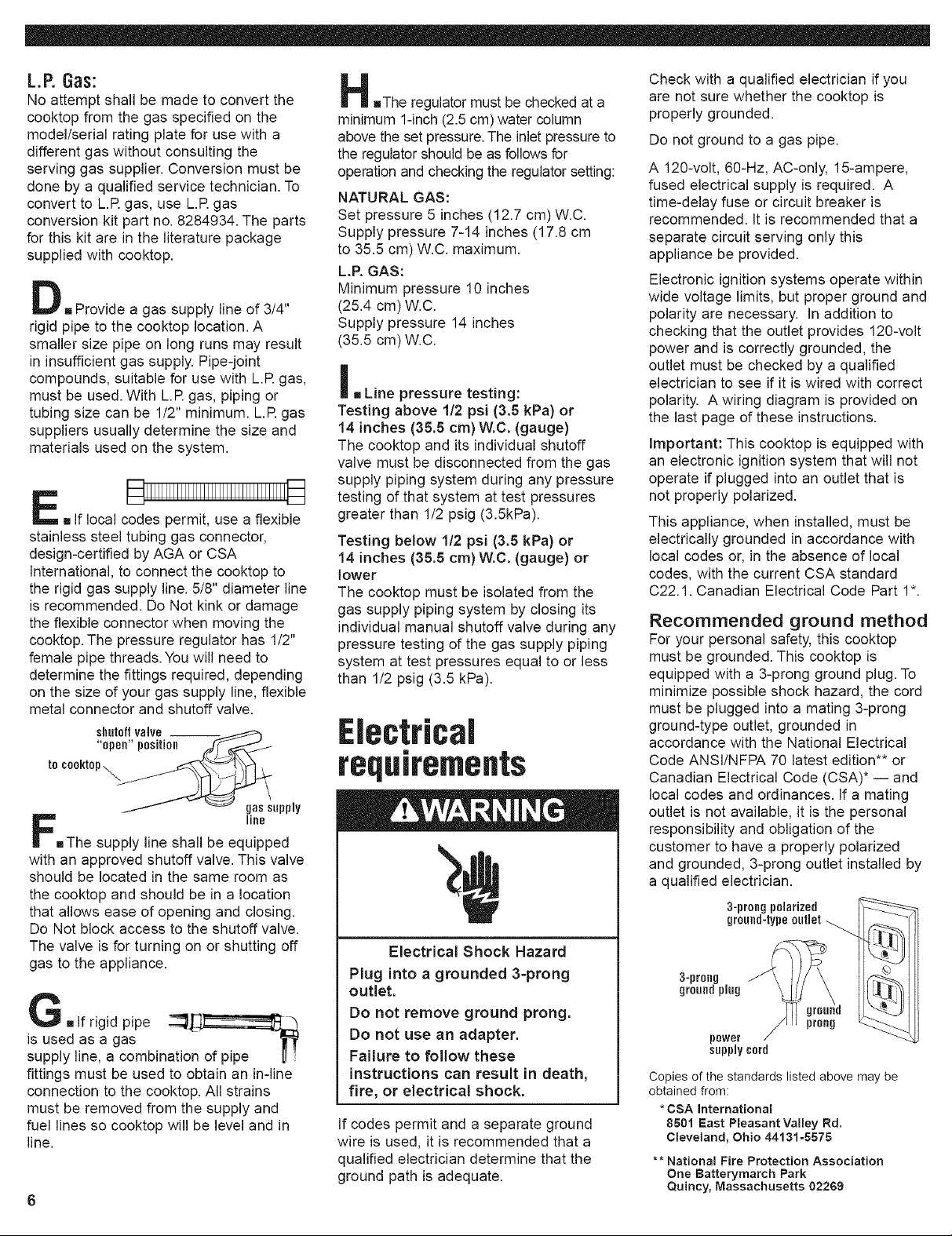
E= If local codes permit, use a flexible
stainless steel tubing gas connector,
design-certified by AGA or CSA
International, to connect the cooktop to
the rigid gas supply line. 5/8" diameter line
is recommended. Do Not kink or damage
the flexible connector when moving the
cooktop. The pressure regulator has 1/2"
female pipe threads. Youwill need to
determine the fittings required, depending
on the size of your gas supply line, flexible
metal connector and shutoff valve.
"open" positi
shutoff va,ve el_-(_________
to coektop__
/ _ gas supply
F line
=The supply line shall be equipped
with an approved shutoff valve. This valve
should be located in the same room as
the cooktop and should be in a location
that allows ease of opening and closing.
Do Not block access to the shutoff valve.
The valve is for turning on or shutting off
gas to the appliance.
G • If rigid pipe :-_J__
is used as a gas I_
supply line, a combination of pipe _l
fittings must be used to obtain an in-line
connection to the cooktop. All strains
must be removed from the supply and
fuel lines so cooktop will be level and in
line.
=The regulator must be checked at a
minimum 1-inch(2.5 cm) water column
above the set pressure.The inlet pressureto
the regulator should be as follows for
operation andchecking the regulator setting:
NATURAL GAS:
Set pressure 5 inches (12.7 cm) W.C.
Supply pressure 7-14 inches (17.8 cm
to 35.5 cm) W.C. maximum.
LP. GAS:
Minimum pressure 10 inches
(25.4 cm) W.C.
Supply pressure 14 inches
(35.5 cm) W.C.
_= Line pressure testing:
Testing above 112psi (3.5 kPa) or
14 inches (35.5 cm)W.C. (gauge)
The cooktop and its individual shutoff
valve must be disconnected from the gas
supply piping system during any pressure
testing of that system at test pressures
greater than 1/2 psig (3.5kPa).
Testing below 1/2 psi (3.5 kPa) or
14 inches (35.5 cm)W.C. (gauge) or
lower
The cooktop must be isolated from the
gas supply piping system by closing its
individual manual shutoff valve during any
pressure testing of the gas supply piping
system at test pressures equal to or less
than 1/2 psig (3.5 kPa).
Electrical
requirements
Electrical Shock Hazard
Plug into a grounded 3-prong
outlet.
Do not remove ground prong.
Do not use an adapter.
Failure to follow these
instructions can result in death,
fire, or electrical shock.
If codes permit and a separate ground
wire is used, it is recommended that a
qualified electrician determine that the
ground path is adequate.
Check with a qualified electrician if you
are not sure whether the cooktop is
properly grounded.
Do not ground to a gas pipe.
A 120-volt, 60-Hz, AC-only, 15-ampere,
fused electrical supply is required. A
time-delay fuse or circuit breaker is
recommended. It is recommended that a
separate circuit serving only this
appliance be provided.
Electronic ignition systems operate within
wide voltage limits, but proper ground and
polarity are necessary. In addition to
checking that the outlet provides 120-volt
power and is correctly grounded, the
outlet must be checked by a qualified
electrician to see if it is wired with correct
polarity. A wiring diagram is provided on
the last page of these instructions.
Important: This cooktop is equipped with
an electronic ignition system that will not
operate if plugged into an outlet that is
not properly polarized.
This appliance, when installed, must be
electrically grounded in accordance with
local codes or, in the absence of local
codes, with the current CSA standard
C22.1. Canadian Electrical Code Part 1".
Recommended ground method
For your personal safety, this cooktop
must be grounded. This cooktop is
equipped with a 3-prong ground plug. To
minimize possible shock hazard, the cord
must be plugged into a mating 3-prong
ground-type outlet, grounded in
accordance with the National Electrical
Code ANSI/NFPA 70 latest edition** or
Canadian Electrical Code (CSA)* -- and
local codes and ordinances. If a mating
outlet is not available, it is the personal
responsibility and obligation of the
customer to have a properly polarized
and grounded, 3-prong outlet installed by
a qualified electrician.
3-prongpolarized
ground-type outlet _
a-prong
ground plug
power
supply cord
Copies of the standards listed above may be
obtained from:
*CSA international
8501 East Pleasant Valley Rd.
Cleveland, Ohio 44131-5578
** National Fire Protection Association
One Batterymarch Park
Quincy, Massachusetts 02269
Installation
t [] Remove the top wood sheet from
over the top of the cooktop.
_ Remove the shipping brackets and
discard.
Excessive Weight Hazard
Use two or more people to move
and install cooktop.
Failure to do so can result in back
or other injury.
= Carefully lift the cooktop up and set
aside. Write down the model and serial
numbers before installing the cooktop.
Both numbers are on the model/serial
number plate located on leftfront
underside of the burner box.
_ Unpack the burner grates, burner
caps, simmer plate, grille grate, drip tray,
spill guard, wave tray,wave plate, tile
bezels, regulator, backguard and island
trim. items are either packaged under the
cooktop or on the cooktop. Parts shipped
with cooktop depend on model ordered.
= The pressure regulator and flexible,
stainless steel gas supply line connector
can be assembled to the cooktop now or
after the cooktop is installed in the cutout.
To assemble now, stand the cooktop on its
side or back surface and complete this
part of the pressure regulator/gas line
connector assembly.
To connect the flexible, stainless steel
connector to the pressure regulator
requires a 1/2" nipple.
Installthe pressure regulator with the
arrow pointing up toward the bottom of the
burner box and in a position where you
can reach the regulator cap.
iMPORTANT: All connections must be
wrench-tightened. Do not make
connections to the gas regulator too tight.
Making the connection too tight may crack
the regulator and cause a gas leak. Do not
allow the regulator to turn on the pipe
when tightening fittings.
Use only pipe-joint compound made for
use with Natural and L.R gas. Do not use
teflon tape. You will need to determine the
fittings required depending on your
installation.
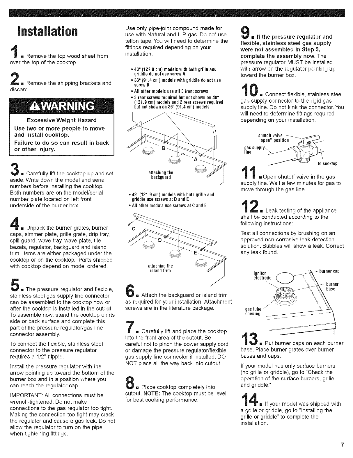
°48"(121.gcm)modelswithbothgrilleand
griddle donotusescrewA
,,36" (91.4 cm) modelswithgriddle donotuse
screw B
• All other models useall 3 front screws
.3 rear screwsrequired bet not shownon48"
(121.g cm) models and 2 rear screwsrequired
but net shown on 36" (91.4 cm) models
attaching the
backgoard
,,48" (121.9 cm) models with both grille and
griddle use screws at D and E
• All other models use screwsat Cand E
c
attaching the
island trim
[] Attach the backguard or island trim
as required for your installation. Attachment
screws are in the literature package.
_ Carefully lift and place the cooktop
intothe front area of the cutout. Be
careful not to pinch the power supply cord
or damage the pressure regulator/flexible
gas supply line connector if installed. DO
NOT place all the way back into cutout.
[] Place cooktop completely into
cutout. NOTE: The cooktop must be level
for best cooking performance.
[] If the pressure regulator and
flexible, stainless steel gas supply
were not assembled in Step 3,
complete the assembly now. The
pressure regulator MUST be installed
with arrow on the regulator pointing up
toward the burner box.
0 [] Connect flexible, stainless steel
gas supply connector to the rigid gas
supply line. Do not kink the connector. You
will need to determine fittings required
depending on your installation.
shuteff valve _
"open" p0sitioe /_
gas supply.. _----'_"1._'! _r_
/ _ to cooktop
11 •Openshutoffvalveinthegas
supply line. Wait a few minutes for gas to
move through the gas line.
t2 [] Leak testing of the appliance
shall be conducted according to the
following instructions:
Test all connections by brushing on an
approved non-corrosive leak-detection
solution. Bubbles will show a leak. Correct
any leak found.
ignitor burner cap
electrode
gas tube "
opening
"_'-_ burner
/
base
3 [] Put burner caps on each burner
base. Place burner grates over burner
bases and caps.
if your model has only surface burners
(no grille or griddle), go to "Check the
operation of the surface burners, grille
and griddle."
4 [] If your model was shipped with
a grille or griddle, go to "Installing the
grille or griddle" to complete the
instaJlation.

lnstaJling the grille
or griddle.
Grille installation: Go to Step 15.
Griddle installation: The griddle is
factory installed. Tocomplete the
installation, go to Step 16.
5 = Installing the grille:
log burner
A= Lifttheiog burnerup outofthe bay
and setaside.
D= Reinstall the log burner. Make sure
burner's rear flange is seated in slot.
E= Plug power supply cord into
grounded outlet.
F= Check the surface burner and grille
flames. Before completing the grille
installation, go to "Check the operation of
the surface burners, grille and griddle."
slot for
g tab
t6 [] Completing the griddle
installation:
griddle
drip tray
A= Place drip tray in the well at the
front of the griddle. Slide tray forward until
it stops.
B. Refer to the Use and Care Guide
that came with your Cooktop for
instructions on cleaning and seasoning
the griddle before using.
locating feet
tray
B= Place drip tray on bottom of grille
bay and slide the tray forward so that it is
located side-to-side and against the
locating feet of the rear spill guard.
%\
locating
tab
/
C= Plug power supply cord into
grounded 3-prong outlet.
D= Check the surface burner and
griddle flames. Go to "Check the
operation of the surface burners, grille
and griddle."
G= Install the wave tray into the
grille/griddle bay. The tab in the leftrear
corner of the bay must fit through the slot
in the left rear corner of the wave tray.
wave wave
}late
\
insert feet
into slots
C= Insert the front spill guard feet into
the slots in the rear spill guard as shown.
The rear flange will rest on the burner box.
8
H= Place the wave plate on the wave
tray as shown. The wave plate must be
centered on the wave tray.
_= install the grille grate.
 Loading...