

Page 1
Installation Instructions
For the way it’s made
®
®
36" (91.4 cm) and 48" (121.9 cm)
Pro Line
for residential use only
™
Gas Cooktop
backguard
(required for some installations)
IMPORTANT:
Read and save these
instructions.
IMPORTANT:
Installer: Leave Installation
Instructions with the homeowner.
Homeowner: Keep Installation
Instructions for future reference.
Save Installation Instructions for local
electrical inspector’s use.
36" (91.4 cm) cooktop with all
sealed burners shown
Questions regarding features,
operation, performance, parts or
service? Call 1-800-422-1230 or visit
our web site at www.kitchenaid.com.
Write down the model and serial numbers
before installing cooktop.
Both numbers are on the model/serial
number plate, located on the left front
underside of the cooktop burner box.
Model #___________________________
Serial # ___________________________
Part No.8285063 Rev. A
Page 2
Before you start...
Your safety and the safety of
others are very important.
We have provided many impor tant
safety messages in this manual and
on your appliance.Always read and
obey all safety messages.
This is the safety alert
symbol.
This symbol alerts you to
potential hazards that can kill or hurt
you and others.
All safety messages will follow the
safety alert symbol and either the
word “DANGER” or “WARNING”.
These words mean:
DANGER
You can be killed or seriously
injured if you don’t immediatel
follow instructions.
WARNING
You can be killed or seriously
injured if you don’t follow
instructions.
All safety messages will tell you
what the potential hazard is, tell you
how to reduce the chance of injury,
and tell you what can happen if the
instructions are not followed.
Important: Observe all governing
codes and ordinances.
y
WARNING: If the
information in this manual
is not followed exactly, a
fire or explosion may result
causing property damage,
personal injury or death.
— Do not store or use
gasoline or other
flammable vapors and
liquids in the vicinity of
this or any other
appliance.
— WHAT TO DO IF YOU
SMELL GAS
• Do not try to light any
appliance.
• Do not touch any
electrical switch.
• Do not use any phone in
your building.
• Immediately call your
gas supplier from a
neighbor’s phone. Follow
the gas supplier’s
instructions.
• If you cannot reach your
gas supplier, call the fire
department.
— Installation and service
must be performed by a
qualified installer, service
agency or the gas
supplier.
Note:This cooktop is manufactured for
use with Natural gas. To convert to
L.P./Propane gas, see the Gas
Conversion instructions provided in
literature package.
Proper gas supply connection
available.See “Gas supply requirements,”
Page 5.
must be
Proper installation is your responsibility.
Have a qualified technician install this
cooktop.
Make sure you have everything
necessary for correct installation. It is the
responsibility of the installer to comply
with the installation clearances specified
on the model/serial rating plate.The
model/serial rating plate can be found on
the underside of the cooktop burner box.
It is recommended that an overhead vent
hood be used with this cooktop.For
island installations, a 48" (122 cm) hood
is recommended.
Check location where cooktop will be
installed.The location should be away
from strong draft areas, such as windows,
doors and strong heating vents or fans.
Do not obstruct flow of combustion and
ventilation air.
All openings in the wall or floor where the
cooktop is to be installed must be sealed.
Electrical ground is required. See
“Electrical Requirements,” Page 6.
It is the customer’s responsibility:
• To contact a qualified electrical
installer.
• To assure that electrical installation is
adequate and in conformance with
National Electrical Code, ANSI/NFPA
70 — latest edition*, or Canadian
Electrical Code, C22.1 -1982 and C22.2
No. 01982 (or latest edition)** and all
local codes and ordinances.
Copies of the standards listed may be obtained
from:
* National Fire Protection Association
One Batterymarch Park
Quincy, Massachusetts 02269
** CSA International
8501 East Pleasant Valley Rd.
Cleveland, Ohio 44131-5575
2
Page 3
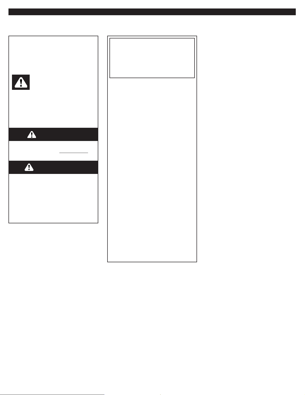
36" (91.4 cm) cooktop
with all sealed burners
shown
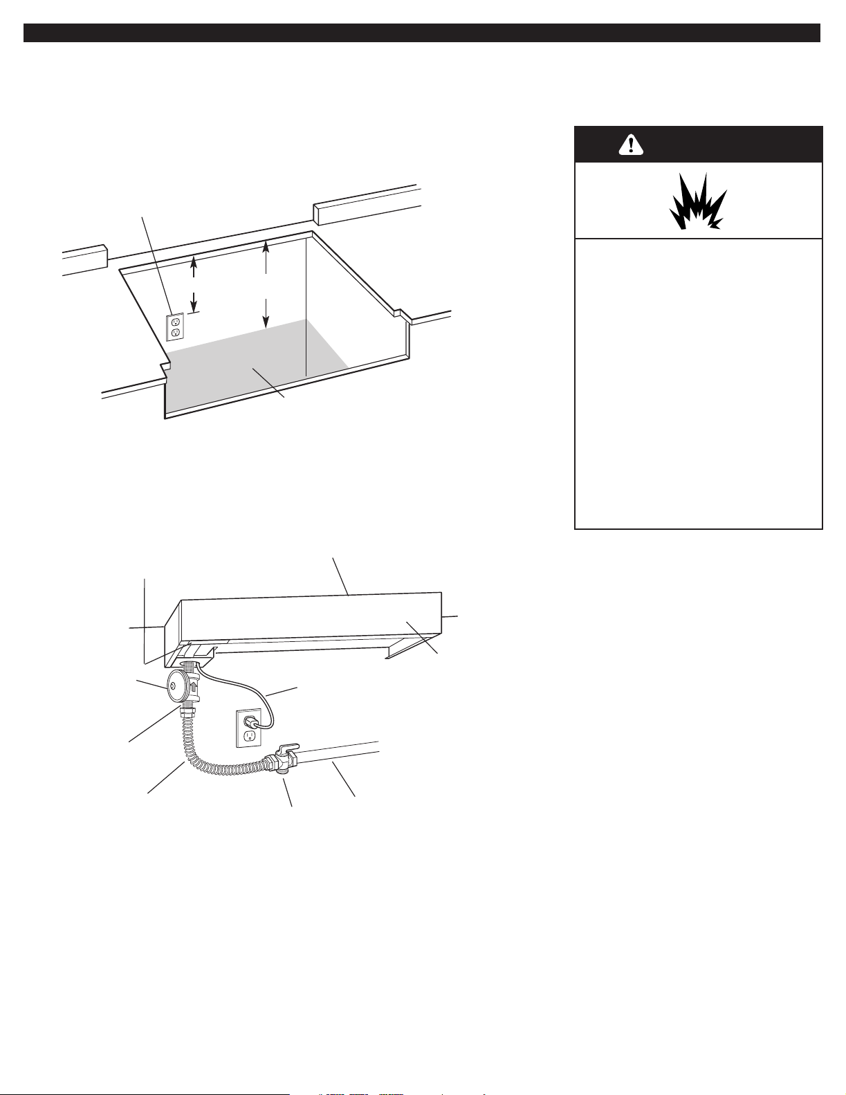
Product Dimensions
backguard (shown)
or island trim
(see Pages 4 and 7)
36" (91.4 cm) long
3-prong groundtype power
supply cord
for 48" (121.9 cm) 8 burner models only:
6" (15.2 cm)
all other models: 9" (22.9 cm)
7-1/2"
(19.1 cm)
26-1/4" (66.7 cm)
36" (91.4 cm) cooktop: 35-7/8" (91.1 cm)
48" (121.9 cm) cooktop: 47-7/8" (121.6 cm)
26-1/4" (66.7 cm)
7/8"
(22.2 mm)
2-3/16"
(55.6 mm)
22" (55.9 cm)
side view of cooktop
for 48" (121.9 cm) 8 burner models only:
6" (15.2 cm)
all other models: 9" (22.9 cm)
3/8"
(9.5 mm)
7-1/8"
(18.1 cm)
gas inlet is located 1-7/8" (4.8 cm) from
back of burner box and
4-7/8" (12.4 cm) in from L.H. side of
burner box
1-3/16"
(30.2 mm)
3
Page 4
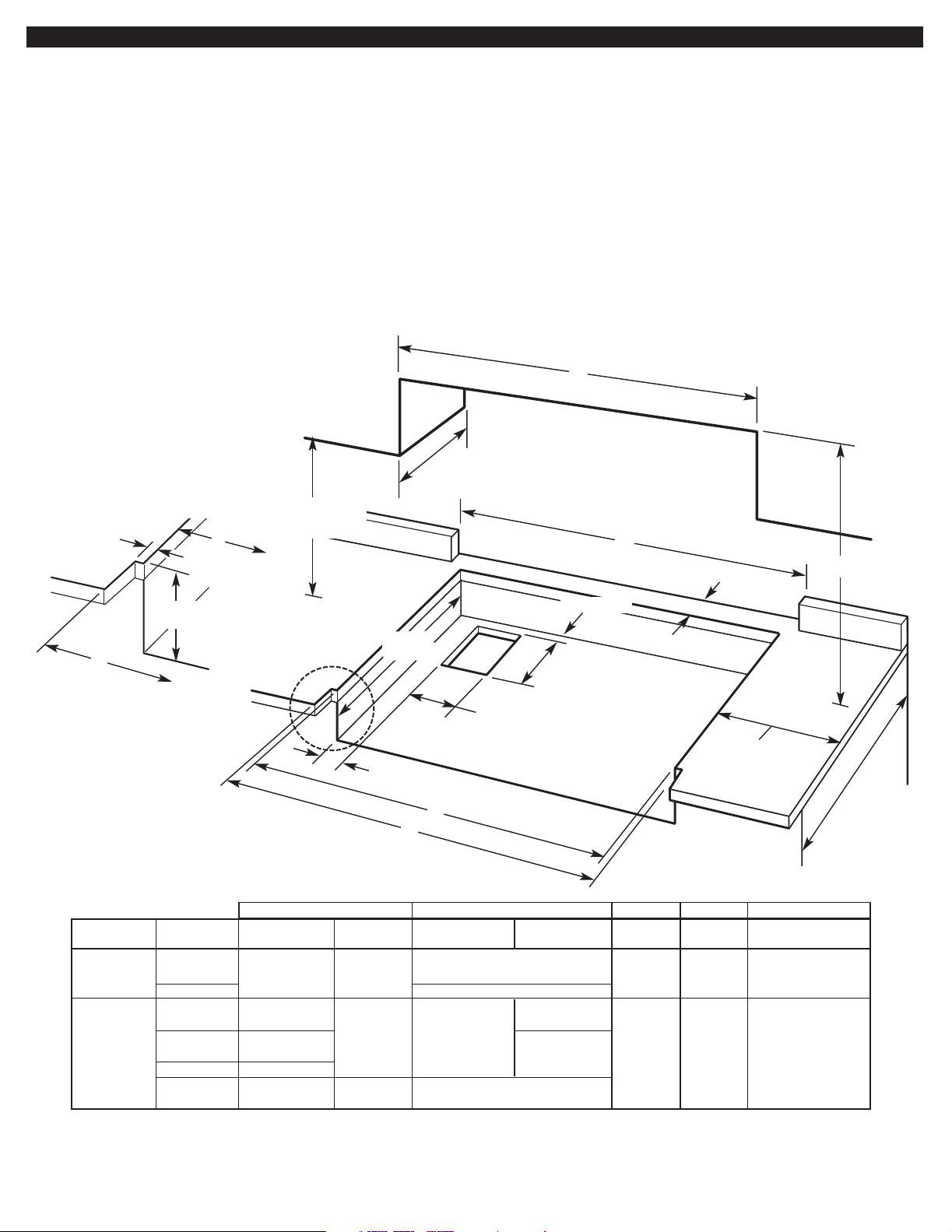
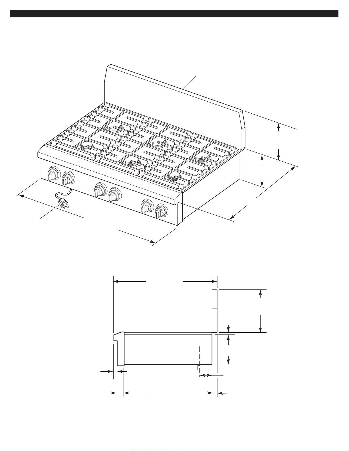
Cabinet and Cutout Dimensions
Countertop opening and clearance
dimensions that are shown must be
used. Given dimensions provide required
clearances.
Mobile home installation: The
installation of this cooktop must conform
to the Manufactured Home Construction
and Safety Standards, Title 24 CFR, Part
3280 (formerly the Federal Standard for
Mobile Home Construction and Safety;
Title 24 HUD part 280); or when such
standard is not applicable, the Standard
for Manufactured Home Installations
(Manufactured Home Sites, Communities
and Setups), ANSI A225.1 — latest
edition*, or with local codes.
18" (45.7 cm) min.
notch to be equal
both sides.
7-1/4"
(18.4 cm)
E
clearance upper
cabinet to countertop
D
notch detail
see corner
In Canada, the installation of this cooktop
must conform with the current standards
CAN/CSA-Z240 — latest edition**, or with
local codes.
The cooktop is designed to hang from the
countertop by its side and rear flanges.
The gas and electric supply should be
located as shown in “Gas and Electric
Dimensions,” Page 5, so that they are
accessible without requiring removal of
the cooktop.
C
13" (33 cm) max.
upper cabinet depth
3/4" (1.9 cm)
22-1/4"
(56.5 cm)
6-7/8" (16.1 cm)
Provide cutout in left rear corner of cutout
enclosure as shown to provide clearance
for gas inlet, power supply cord, and to
allow the rating label to be visible.
Copies of the standards listed may be
obtained from:
* National Fire Protection Association
One Batterymarch Park
Quincy, Massachusetts 02269
** CSA International
8501 East Pleasant Valley Rd.
Cleveland, Ohio 44131-5575
C
min.
A
B
CORNER NOTCH
DETAIL
2"
(5.1 cm)
D
4-3/4"
(12.1 cm)
12-5/16" (31.3 cm)
min. clearance to
side wall both sides
base cabinet
E
AB (min.) C D E
size model island trim backguard island trim backguard opening countertop countertop only
36" (91.4 cm) KGCP462K 5" 1-3/4" 48" (121.9 cm) 36" 35-1/4" 36" (91.4 cm) or
KGCP463K (12.7 cm) (4.4 cm) (91.4 cm) (89.5 cm) 35-7/8" (91.1 cm)
KGCP467J 49" (124.5 cm) for zero clearance fit
48" (121.9 cm) KGCP482K 6" 1-3/4" 48" 49" 48" 47-1/4" 48" (121.9 cm) or
(15.2 cm) (4.4 cm) (121.9 cm) (124.5 cm) (121.9 cm) (120.0 cm) 47-7/8" (121.6 cm)
KGCP483K 5" 48" for zero clearance fit
(12.7 cm) (121.9 cm)
KGCP484K 6" (15.2 cm)
KGCP487J 5" 5" 48" (121.9 cm)
(12.7 cm) (12.7 cm)
Note: Dimension "B" can be reduced by 6" (15.2 cm) when bottom of wood or metal cabinet is protected by not less than 0.25" (6.4 mm) flame retardant
millboard covered with not less than No. 28 MSG sheet steel, 0.015" (0.4 mm) stainless steel, 0.024" (0.6 mm) aluminum or 0.020" (0.5 mm) copper.
backguard cabinet and
24"
(61 cm)
4
Page 5
Gas and Electric
Gas supply
Dimensions
3-prong ground-type outlet
should be located on left hand
side of cutout 8" (20.3 cm)
max. from enclosure sidewall.
10" (25.4 cm)
Gas and Electric
Connection Locations
14"
(35.6 cm)
Gas supply line should be
located in this area on rear or
side walls, or the supply line can
come up through the floor.
Note: Solid side and
bottom of cutout
enclosure not shown.
requirements
WARNING
Explosion Hazard
Use a new AGA or CSA approved
gas supply line.
Install a shut-off valve.
Securely tighten all gas
connections.
If connected to LP, have a
qualified person make sure gas
pressure does not exceed 14"
water column.
Examples of a qualified person
include licensed heating
personnel, authorized gas
company personnel, and
authorized service personnel.
Failure to do so can result in
death, explosion, or fire .
product rating/serial tag
regulator (supplied
with product) must be
installed with arrow up
pointing at cooktop
bottom
1/2" nipple
(not supplied)
AGA or CSA approved
flexible stainless
steel gas supply line
(not supplied)
control support panel
36" (91.4 cm)
3-prong ground-type
power supply cord
shut off valve
(not supplied)
Typical Gas and Electric
Connections
Copies of the standards listed may be
obtained from:
* CSA International
8501 East Pleasant Valley Rd.
Cleveland, Ohio 44131-5575
regulated gas
supply line
Front of
Cooktop
Observe all governing codes and
ordinances.
Important: Cooktop must be connected
to a regulated gas supply.
A.This installation must conform with
local codes and ordinances. In the
absence of local codes, installations must
conform with American National
Standard, National Fuel Gas Code
ANSI Z223.1 — latest edition or
CANI — B149.1 or 2*.
B.Input ratings shown on the
model/serial rating plate are for elevations
up to 2,000 feet (610 m). For elevations
above 2,000 feet (610 m), ratings are
reduced at a rate of 4% for each 1,000
feet (305 m) above sea level.
C.The cooktop is equipped for use
with NATURAL gas. It is design-certified
by Inter national Approval Services (I.A.S.)
for NATURAL and L.P. gases with
appropriate conversion.The model/serial
rating plate, located on the underside of
the burner box, has information on the
type of gas that can be used. If this
information does not agree with the type
of gas available, check with the local gas
supplier.
5
Page 6
L.P. Gas:
No attempt shall be made to convert the
cooktop from the gas specified on the
model/serial rating plate for use with a
different gas without consulting the
serving gas supplier. Conversion must be
done by a qualified service technician.To
convert to L.P. gas, use L.P. gas
conversion kit part no.8284934.The parts
for this kit are in the literature package
supplied with cooktop.
D.Provide a gas supply line of 3/4"
rigid pipe to the cooktop location. A
smaller size pipe on long runs may result
in insufficient gas supply. Pipe-joint
compounds, suitable for use with L.P. gas,
must be used.With L.P. gas, piping or
tubing size can be 1/2" minimum. L.P. gas
suppliers usually determine the size and
materials used on the system.
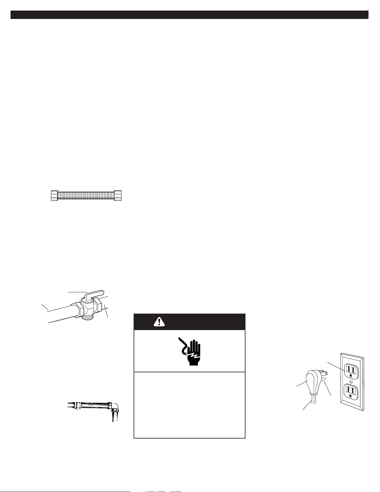
E.If local codes permit, use a flexible
stainless steel tubing gas connector,
design-certified by AGA or CSA
International, to connect the cooktop to
the rigid gas supply line. 5/8" diameter line
is recommended. Do Not kink or damage
the flexible connector when moving the
cooktop.The pressure regulator has 1/2"
female pipe threads.You will need to
determine the fittings required, depending
on the size of your gas supply line, flexible
metal connector and shutoff valve.
shutoff valve
“open” position
to cooktop
gas supply
line
F.The supply line shall be equipped
with an approved shutoff valve.This valve
should be located in the same room as
the cooktop and should be in a location
that allows ease of opening and closing.
Do Not block access to the shutoff valve.
The valve is for turning on or shutting off
gas to the appliance.
G.If rigid pipe
is used as a gas
supply line, a combination of pipe
fittings must be used to obtain an in-line
connection to the cooktop.All strains
must be removed from the supply and
fuel lines so cooktop will be level and in
line.
6
H.The regulator must be checked at a
minimum 1-inch (2.5 cm) water column
above the set pressure.The inlet pressure to
the regulator should be as follows for
operation and checking the regulator setting:
NATURAL GAS:
Set pressure 5 inches (12.7 cm) W.C.
Supply pressure 7-14 inches (17.8 cm
to 35.5 cm) W.C. maximum.
L.P. GAS:
Minimum pressure 10 inches (25.4 cm)
W.C.
Supply pressure 14 inches (35.5 cm)
W.C.
I.Line pressure testing:
Testing above 1/2 psi (3.5 kPa) or
14 inches (35.5 cm) W.C. (gauge)
The cooktop and its individual shutoff
valve must be disconnected from the gas
supply piping system during any pressure
testing of that system at test pressures
greater than 1/2 psig (3.5kPa).
Testing below 1/2 psi (3.5 kPa) or
14 inches (35.5 cm) W.C. (gauge) or
lower
The cooktop must be isolated from the
gas supply piping system by closing its
individual manual shutoff valve during any
pressure testing of the gas supply piping
system at test pressures equal to or less
than 1/2 psig (3.5 kPa).
Electrical requirements
WARNING
Electrical Shock Hazard
Plug into a grounded 3-prong
outlet.
Do not remove ground prong.
Do not use an adapter.
Failure to follow these
instructions can result in death,
fire, or electrical shock.
If codes permit and a separate ground
wire is used, it is recommended that a
qualified electrician determine that the
ground path is adequate.
Check with a qualified electrician if
you are not sure whether the cooktop
is properly grounded.
Do Not ground to a gas pipe.
A 120-volt, 60-Hz, AC-only, 15-ampere,
fused electrical supply is required. A
time-delay fuse or circuit breaker is
recommended. It is recommended that a
separate circuit serving only this
appliance be provided.
Electronic ignition systems operate within
wide voltage limits, but proper ground and
polarity are necessary. In addition to
checking that the outlet provides 120-volt
power and is correctly grounded, the
outlet must be checked by a qualified
electrician to see if it is wired with correct
polarity. A wiring diagram is provided on
the last page of these instructions.
Important: This cooktop is equipped with
an electronic ignition system that will not
operate if plugged into an outlet that is
not properly polarized.
This appliance, when installed, must be
electrically grounded in accordance with
local codes or, in the absence of local
codes, with the current CSA standard
C22.1. Canadian Electrical Code Part 1*.
Recommended ground method
For your personal safety, this cooktop
must be grounded.This cooktop is
equipped with a 3-prong ground plug.To
minimize possible shock hazard, the cord
must be plugged into a mating 3-prong
ground-type outlet, grounded in
accordance with the National Electrical
Code ANSI/NFPA 70 latest edition** or
Canadian Electrical Code (CSA)* — and
local codes and ordinances. If a mating
outlet is not available, it is the personal
responsibility and obligation of the
customer to have a properly polarized
and grounded, 3-prong outlet installed by
a qualified electrician.
3-prong polarized
ground-type outlet
3-prong
ground plug
ground
prong
power
supply cord
Copies of the standards listed above may be
obtained from:
*CSA International
8501 East Pleasant Valley Rd.
Cleveland, Ohio 44131-5575
** National Fire Protection Association
One Batterymarch Park
Quincy, Massachusetts 02269
Page 7
Installation
1.Remove the top wood sheet from
over the top of the cooktop.
2.Remove the shipping brackets and
discard.
WARNING
Excessive Weight Hazard
Use two or more people to move
and install cooktop.
Failure to do so can result in back
or other injury.
3.Carefully lift the cooktop up and set
aside.Write down the model and serial
numbers before installing the cooktop.
Both numbers are on the model/serial
number plate located on left front
underside of the burner box.
4.Unpack the burner grates, burner
caps, simmer plate, grille grate, drip tray,
spill guard, wave tray, wave plate, tile
bezels, regulator, backguard and island
trim. Items are either packaged under the
cooktop or on the cooktop. Parts shipped
with cooktop depend on model ordered.
5.The pressure regulator and flexible,
stainless steel gas supply line connector
can be assembled to the cooktop now or
after the cooktop is installed in the cutout.
To assemble now, stand the cooktop on its
side or back surface and complete this
part of the pressure regulator/gas line
connector assembly.
To connect the flexible, stainless steel
connector to the pressure regulator
requires a 1/2" nipple.
Install the pressure regulator with the
arrow pointing up toward the bottom of the
burner box and in a position where you
can reach the regulator cap.
Use only pipe-joint compound made for
use with Natural and L.P. gas. Do not use
teflon tape.You will need to determine the
fittings required depending on your
installation.
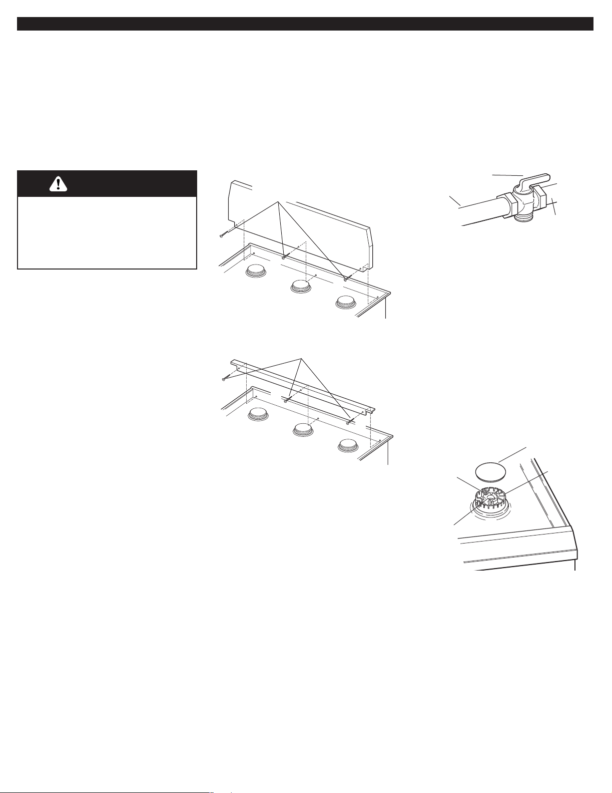
• 48" (121.9 cm) models with both grille
and griddle: do not use screw
• 36" (91.4 cm) models with griddle: do
not use screw
• All other models use all 3 front screws
• 3 rear screws required but not shown
for all models
attaching the
backguard
• 48" (121.9 cm) models with both grille
and griddle: use screws at and
• All other models use screws at and
attaching the
island trim
6.Attach the backguard or island trim
as required for your installation.Attachment
screws are in the literature package.
7.Carefully lift and place the cooktop
into the front area of the cutout. Be
careful not to pinch the power supply cord
or damage the pressure regulator/flexible
gas supply line connector if installed. DO
NOT place all the way back into cutout.
8.Place cooktop completely into
cutout. Note: The cooktop must be level
for best cooking performance.
10.Connect flexible, stainless steel
gas supply connector to the rigid gas
supply line. Do not kink the connector.You
will need to determine fittings required
depending on your installation.
shutoff valve
“open” position
to cooktop
gas supply
line
11.Open shutoff valve in the gas
supply line.Wait a few minutes for gas to
move through the gas line.
12.Leak testing of the appliance
shall be conducted according to the
following instructions:
Use a brush and liquid detergent to test
all gas connections for leaks.Bubbles
around connections will indicate a leak. If
a leak appears, shut off gas valve
controls and adjust connections.Then
check connections again. Clean all
detergent solution from cooktop.
burner cap
ignitor
electrode
gas tube
opening
burner
base
13.Put burner caps on each burner
base. Place burner grates over burner
bases and caps.
If your model has only surface burners
(no grille or griddle), go to "Check the
operation of the surface burners, grille
and griddle" on Page 9.
9.
If the pressure regulator and
flexible, stainless steel gas supply were
not assembled in Step 3, complete the
assembly now. The pressure regulator
MUST be installed with arrow on the
regulator pointing up toward the burner
box.
14.If your model was shipped with
a grille or griddle, go to "Installing the
grille or griddle" on Page 8 to complete
the installation.
7
Page 8
Installing the grille
or griddle.
Grille installation: Go to Step 15.
Griddle installation: The griddle is
factory installed.To complete the
installation, go to Step 16.
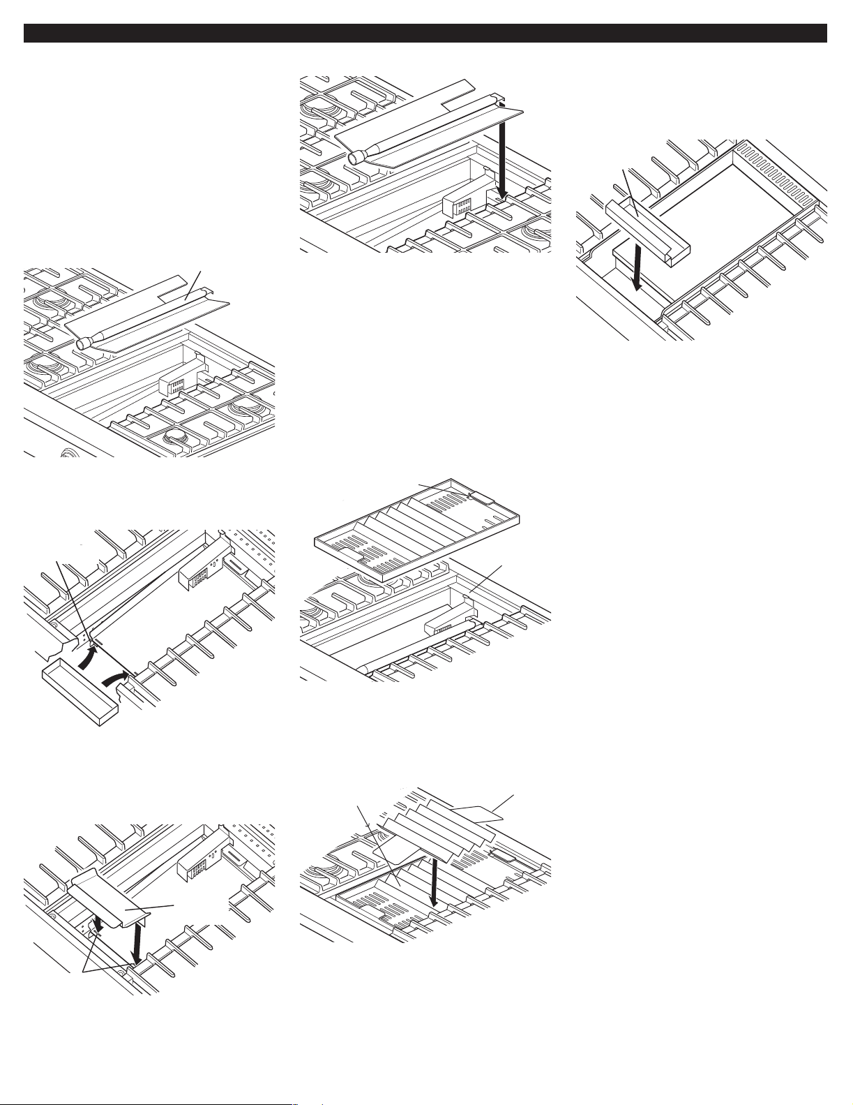
15.Installing the grille:
log burner
A. Lift the log burner up out of the bay
and set aside.
D. Reinstall the log burner.Make sure
burner’s rear flange is seated in slot.
E. Plug power supply cord into
grounded outlet.
F. Check the surface burner and grille
flames. Before completing the grille
installation, go to "Check the operation
of the surface burners, grille and griddle"
on Page 9.
slot for
locating tab
16.Completing the griddle
installation:
griddle
drip tray
griddle
A. Place drip tray in the well at the
front of the griddle. Slide tray forward until
it stops.
B. Refer to the Use and Care Guide
that came with your Cooktop for
instructions on cleaning and seasoning
the griddle before using.
locating feet
rear spill
guard
drip
tray
B. Place dr ip tray on bottom of grille
bay and slide the tray forward so that it is
located side-to-side and against the
locating feet of the rear spill guard.
front spill
guard
locating
tab
G. Install the wave tray into the
grille/griddle bay.The tab in the left rear
corner of the bay must fit through the slot
in the left rear corner of the wave tray.
wave
tray
wave
plate
C. Plug power supply cord into
grounded outlet.
D. Check the surface burner and
griddle flames. Go to "Check the
operation of the surface burners, grille
and griddle" on Page 9.
insert feet
into slots
C. Insert the front spill guard feet into
the slots in the rear spill guard as shown.
The rear flange will rest on the burner box.
8
H. Place the wave plate on the wave
tray as shown.The wave plate must be
centered on the wave tray.
I. Install the grille grate.
Page 9

Check the
operation of the
surface burners,
grille and griddle.
Electronic Ignition System —
initial lighting
Surface burners use electronic ignitors
in place of standing pilots.When the
cooktop control knob is pushed in and
turned to the “LITE” position, the system
creates a spark to light the burner.This
sparking continues until the control knob
is turned to the desired setting.
The grille and griddle burner use an
ignitor glow bar that is either on or off in
place of standing pilots.When the glow
bar is hot, it sends a signal back to the
safety valve which opens allowing gas to
flow.
cooktop
burners
A. Push in and turn the surface
burners and grille control knobs to “LITE”
position. For griddles, turn the griddle
control knob to a temperature degree
mark (300° recommended). The surface
burner flame should light within 4
seconds and the grille and griddle flame
in 30-40 seconds. Note: the griddle flame
cannot be seen, but you should hear it
ignite and feel heat from the griddle.
After lighting the burners, turn the
control knobs "OFF".
If burners do not light properly, turn
control knob to the “OFF” position. Check
that burner cap is in the proper position.
Check that power supply cord is plugged
in and that circuit breaker or house fuse
has not blown.Check that the shutoff
valve is in the “ON” position. Check
operation again.
If a surface burner, grille or griddle does
not light at this point, contact your
KitchenAid dealer for assistance.
grille
knob
griddle
knob
valve
stem
B. Adjusting the surface burner or
grille flame: Note: there is no adjustment
for the griddle flame.Gas flow is at 100%,
temperature is controlled by thermostat.
Push in and turn each control knob to the
“LO” position.The “LO” setting of each
burner has been factory set to the lowest
position available to provide reliable
reignition of the burner.If it does not stay
lit on the “LO” position, check “LO”
position as follows:
a.Tur n control knob to “LITE” until burner
ignites.
b. Quickly turn control knob down to “LO”
position.
c. If burner goes out, readjust valve as
follows:
Remove control knob. Insert a flat-blade
screwdriver into the hollow valve stem
and engage the slotted screw. Flame size
can be increased or decreased by turning
the screw. Adjust flame until you can
quickly turn control knob from “HI” to “LO”
position without extinguishing the flame.
Flame should be as small as possible
without going out.
ports
typical surface
burner flame at
highest setting
C. Check flame on “HI” for a blue
color.It should be clean and soft in
character.No yellow tip, blowing or lifting
of flame should occur.Occasional orange
flashes are normal and reflect different
elements in the air or gas.
9
Page 10

Installer checkoff
If cooktop does
If you need
list:
COOKTOP
Cooktop correctly positioned in
✓
countertop cutout.
Maintained specified distances to
✓
cabinet surfaces.
Cooktop level – front to back – side
✓
to side.
Burner caps positioned properly on
✓
sealed burner bases.
All packing material removed.
✓
Backguard or island trim attached
✓
(see page 4).
Depending on model, grille parts
✓
correctly assembled.
Depending on model, griddle parts
✓
correctly assembled.
ELECTRICAL
Polarized and grounded 120-volt,
✓
60-Hz, AC, 15-amp fused electrical
supply for power supply cord
connection.
GAS SUPPLY
Connection: 1/2" NPT with a
✓
minimum 5/8" (15.9 mm) diameter
flex line.
The cooktop is connected only to
✓
type of gas for which it is certified for
use.
not operate:
Check that the circuit breaker is not
✓
tripped or the house fuse blown.
Check that the power supply cord is
✓
plugged into the outlet.
Check that gas valves are turned to
✓
the “ON” position.
See Use and Care Guide for
✓
troubleshooting list.
If you need
assistance:
The KitchenAid Consumer Assistance Center
will answer any questions about operating or
maintaining your cooktop not covered in the
Installation Instructions.The KitchenAid
Consumer Assistance Center is open 24
hours a day, 7 days a week. Just dial 1-800422-1230 — the call is free within the
continental United States, or visit our web site
at www.kitchenaid,com.
When you call, you will need the cooktop
model number and serial number.Both
numbers can be found on the model/serial
rating plate located on the bottom of the
cooktop and are visible through the cutout in
the left-hand back corner of the enclosure
bottom.
service:
In the event that your KitchenAid
appliance should need service, call the
dealer from whom you purchased the
appliance or a KitchenAid-designated
service company. A KitchenAiddesignated service company is listed in
the Yellow Pages of your telephone
directory under “Appliances —
Household — Major — Service and
Repair.”
You can also obtain the service
company's name and number by dialing,
free within the continental United States,
the KitchenAid Consumer Assistance
Center telephone number, 1-800-422-
1230. A special operator will tell you the
name of your nearest KitchenAiddesignated service company.
Maintain the quality built into your
KitchenAid appliance — call a
KitchenAid-designated service company.
Maintenance
If removing the cooktop is necessary for
maintenance, shut off gas supply.
Disconnect the gas and electric supply.
After disconnecting the gas and electric
supply, finish removing the cooktop.
Generally, the cooktop does not need to
be removed for servicing.
10
Page 11

36" (91.4 cm) cooktop models
THE POWER CORD ON THIS APPLIANCE IS EQUIPPED WITH A 3-PRONG GROUND PLUG WHICH MATES WITH STANDARD 3-PRONG
GROUND-TYPE OUTLET.
CAUTION: LABEL ALL WIRES PRIOR TO DISCONNECTION WHEN SERVICING CONTROLS. WIRING ERRORS CAN CAUSE IMPROPER
AND DANGEROUS OPERATION.
VERIFY PROPER OPERATION AFTER SERVICING.
6 surface burners 4 surface burners with grille
LINE
1/4 WIDE
BLADE
CONNECT
.250 TERMINALS
BLK
SWITCHES ON SURFACE
ELECTRIC CIRCUIT CLOSED
WHEN KNOB IS ROTATED 55°
TO 95° COUNTER CLOCKWISE
FROM OFF
PLUG
WHT
SURFACE BURNER
VALVE
SWITCHES
4 surface burners with griddle
LINE
1/4 WIDE
BLADE
PLUG
BK
NEUTRAL
5/16 WIDE
BLADE
GROUND
ROUND BLADE
GRN OR GRN/Y
WHT
BURNER VALVES:
NEUTRAL
5/16 WIDE
BLADE
GROUND
ROUND BLADE
BK RIB
GRN OR GRN/Y
WHT
IGNITOR
ELECTRODES
W
W
GROUND
SPARK
MODULE
GROUND
120 VAC 60 Hz
1 PHASE
15 OR 20 AMP
WHT
BLK
YEL OR BRN
6 PLCS
120 VAC 60 Hz
1 PHASE
15 OR 20 AMP
BK
BK
W
GRIDDLE
VALVE
LINE
1/4 WIDE
BLADE
SWITCHES ON SURFACE
ELECTRIC CIRCUIT CLOSED
WHEN KNOB IS ROTATED 55°
TO 95° COUNTER CLOCKWISE
FROM OFF
PLUG
BK
BK RIB
BK
SURFACE BURNER
VALVE
SWITCHES
BK
GRILLE
VALVE
SWITCH
BURNER VALVES:
NEUTRAL
5/16 WIDE
BLADE
GROUND
ROUND BLADE
GRN OR GRN/Y
BK
W
SURFACE BURNER
ELECTRODES
120 VAC 60 Hz
1 PHASE
15 OR 20 AMP
GROUND
W
W
IGNITOR
SWITCH ON GRILLE VALVE:
ELECTRIC CIRCUIT CLOSED
WHEN KNOB IS ROTATED 20°
TO 360° COUNTER CLOCKWISE
FROM OFF
SPARK
MODULE
YEL OR BRN
4 PLCS
BK
GRILLE
IGNITOR
W
GRILLE
VALVE
BK
VALVE
BK
W
SURFACE BURNER
BURNER VALVES:
BK
SURFACE BURNER
SWITCHES
BK
GRIDDLE
THERMOSTAT
SWITCHES ON SURFACE
ELECTRIC CIRCUIT CLOSED
WHEN KNOB IS ROTATED 55°
TO 95° COUNTER CLOCKWISE
FROM OFF
IGNITOR
ELECTRODES
SPARK
MODULE
YEL OR BRN
4 PLCS
GRIDDLE
IGNITOR
11
Page 12

SWITCHES ON SURFACE
BURNER VALVES:
ELECTRIC CIRCUIT CLOSED
WHEN KNOB IS ROTATED 55°
TO 95° COUNTER CLOCKWISE
FROM OFF
PLUG
GROUND
ROUND BLADE
GRN OR GRN/Y
GROUND
BLK
WHT
CONNECT
.250 TERMINALS
VALVE
SWITCHES
120 VAC 60 Hz
1 PHASE
15 OR 20 AMP
IGNITOR
ELECTRODES
WHT
SPARK
MODULE
YEL OR BRN
6 PLCS
WHT
WHT
BLK
NEUTRAL
5/16 WIDE
BLADE
LINE
1/4 WIDE
BLADE
SURFACE BURNER
CAUTION: LABEL ALL WIRES PRIOR TO DISCONNECTION WHEN SERVICING CONTROLS. WIRING ERRORS CAN CAUSE IMPROPER
AND DANGEROUS OPERATION.
VERIFY PROPER OPERATION AFTER SERVICING.
THE POWER CORD ON THIS APPLIANCE IS EQUIPPED WITH A 3-PRONG GROUND PLUG WHICH MATES WITH STANDARD 3-PRONG
GROUND-TYPE OUTLET.
PLUG
GRN OR GRN/Y
GROUND
SURFACE BURNER
VALVE
SWITCHES
SURFACE BURNER
IGNITOR
ELECTRODES
GRILLE
VALVE
SWITCH
GRILLE
IGNITOR
W
BK
BK
W
BK RIB
BK
W
BK
W
BK
BK
YEL OR BRN
6 PLCS
W
BK
SP ARK
MODULE
NEUTRAL
5/16 WIDE
BLADE
LINE
1/4 WIDE
BLADE
GROUND
ROUND BLADE
120 VAC 60 Hz
1 PHASE
15 OR 20 AMP
GRILLE
VALVE
PLUG
GROUND
ROUND BLADE
GRN OR GRN/Y
GROUND
SURFACE BURNER
VALVE
SWITCHES
SURFACE BURNER
IGNITOR
ELECTRODES
GRIDDLE
THERMOSTAT
GRIDDLE
IGNITOR
GRIDDLE
VALVE
WBK
BK
W
BK
BK RIB
W
BK
W
BK
BK
YEL OR BRN
6 PLCS
W
BK
SP ARK
MODULE
120 VAC 60 Hz
1 PHASE
15 OR 20 AMP
NEUTRAL
5/16 WIDE
BLADE
LINE
1/4 WIDE
BLADE
SWITCHES ON SURFACE
BURNER VALVES:
ELECTRIC CIRCUIT CLOSED
WHEN KNOB IS ROTATED 55°
TO 95° COUNTER CLOCKWISE
FROM OFF
8 surface burners 6 surface burners with grille
6 surface burners with griddle
PLUG
GROUND
ROUND BLADE
GRN OR GRN/Y
GROUND
SURFACE BURNER
VALVE
SWITCHES
120 VAC 60 Hz
1 PHASE
15 OR 20 AMP
SURFACE BURNER
IGNITOR
ELECTRODES
GRIDDLE
THERMOSTAT
GRILLE
IGNITOR
GRILLE
VALVE
W
BK
BK
W
BK
BK RIB
W
BK
W
BK
BK
W
BK
SPARK
MODULE
GRIDDLE
IGNITOR
GRIDDLE
VALVE
BK
W
BK
W
W
W
BK
BK
GRILLE
VALVE SWITCH
SWITCHES ON SURFACE
BURNER VALVES:
ELECTRIC CIRCUIT CLOSED WHEN KNOB IS
ROTATE D 55° TO 95° COUNTER CLOCKWISE
FROM OFF
LINE
1/4 WIDE
BLADE
NEUTRAL
5/16 WIDE
BLADE
YEL OR BRN
4 PLCS
4 surface burners with grille and griddle
ELECTRIC CIRCUIT CLOSED WHEN
KNOB IS ROTATED 55° TO 95°
COUNTER CLOCKWISE FROM OFF
ELECTRIC CIRCUIT CLOSED WHEN
KNOB IS ROTATED 20° TO 360°
COUNTER CLOCKWISE FROM OFF
SWITCHES ON SURFACE
BURNER VALVES:
SWITCH ON GRILLE VALVE:
48" (121.9 cm) cooktop models
Part No.8285063 Rev. A
© 2002 KitchenAid.
® Registered Trademark/Trademark of
KitchenAid U.S.A., KitchenAid
Canada licensee in Canada
Prepared by KitchenAid, Benton Harbor, Michigan 49022
®
Printed in U.S.A.
Page 13

Instructions d’installation
For the way it’s made
®
®
Table de cuisson à gaz professionnelle
Pro Line
™
de 91,4 cm (36 po) et
121,9 cm (48 po) pour utilisation
résidentielle seulement
Dosseret
(nécessaire pour certaines
installations)
IMPORTANT :
Lire et conserver ces
instructions.
IMPORTANT :
Installateur : Remettre les instructions
d’installation au propriétaire.
Propriétaire : Conserver les instructions
d’installation pour consultation ultérieure.
Conserver les instructions d’installation
pour consultation par l’inspecteur local
des installations électriques.
Table de cuisson à brûleurs
scellés de 91,4 cm (36 po)
Pour toute question concernant
®
Bien pensé, bien fabriqué
Inscrire ci-dessous les numéros de
modèle et de série avant d’installer la
table de cuisson.
On trouve cette information sur la plaque
signalétique, sur la surface interne du
coffret des brûleurs.
N° de modèle
N° de série
caractéristiques, utilisation, performance,
pièce ou service, téléphoner au
1-800-422-1230 ou consulter notre site
Internet à l’adresse www.kitchenaid.com
N° de pièce 8285063 Rév. A
Page 14

Avant de commencer...
Votre sécurité et celle des autres
est très importante.
Nous donnons de nombreux
messages de sécurité importants dans
ce manuel et sur votre appareil
ménager.Assurez-vous de toujours
lire tous les messages de sécurité et
de vous y conformer.
Voici le symbole d’alerte de
sécurité.
Ce symbole d’alerte de
sécurité vous signale les dangers
potentiels de décès et de blessures
graves à vous et à d’autres.
Tous les messages de sécur ité
suivront le symbole d’alerte de
sécurité et le mot “DANGER”ou
“AVERTISSEMENT”. Ces mots
signifient :
DANGER
Risque possible de décès ou de
blessure grave si vous ne suivez pas
immédiatement
AVERTISSEMENT
Risque possible de décès ou de
blessure grave si vous ne suivez
pas les instructions.
Tous les messages de sécur ité vous
diront quel est le danger potentiel et
vous disent comment réduire le risque
de blessure et ce qui peut se produire
en cas de non-respect des instructions.
Important : Observer les dispositions
de tous les codes et règlements en
vigueur.
2
les instructions.
Remarque : Cette table de cuisson est
conçue pour l’alimentation au gaz
naturel. Pour la conversion au gaz
propane, voir les instructions de
conversion présentées dans les
documents qui accompagnent le produit.
Un raccord de connexion à la
canalisation d’arrivée de gaz doit être
disponible.Voir “Spécifications de
l’alimentation en gaz” à la page 5.
AVERTISSEMENT : Si les
instructions dans ce
manuel ne sont pas
suivies, un incendie ou une
explosion peut causer des
dommages aux biens, une
blessure ou un décès.
— Ne pas remiser ou utiliser
d’essence ou un autre
produit liquide ou gazeux
inflammable à proximité
de cet appareil ou de tout
autre appareil
électroménager.
— QUE FAIRE SI UNE
ODEUR DE GAZ EST
PERCEPTIBLE?
• Ne pas essayer de
mettre un appareil en
marche.
• Ne toucher aucun
commutateur électrique.
• N’utiliser aucun
téléphone de l’édifice.
• Contacter
immédiatement le
fournisseur de gaz
depuis le téléphone d’un
voisin. Exécuter les
instructions du
fournisseur.
• Si le fournisseur de gaz
n’est pas accessible,
appeler les pompiers.
— L’installation et les
travaux de service doivent
être effectués par un
électricien qualifié, par
une agence de service ou
par le fournisseur de gaz.
La responsabilité de la qualité de
l’installation incombe au propriétaire.
Demander à un technicien qualifié
d’exécuter l’installation.
Vérifier que tout le matériel nécessaire
pour une installation correcte est
disponible.C’est à l’installateur
qu’incombe la responsabilité de respecter
les dégagements de séparation spécifiés
sur la plaque signalétique. On trouve la
plaque signalétique sur la face inférieure
du coffret des brûleurs.
On recommande qu’une hotte d’extraction
soit installée au-dessus de la table de
cuisson. Pour l’installation sur un îlot, on
recommande une hotte de 122 cm (48
po).
Inspecter l’emplacement où la table de
cuisson sera installée. L’emplacement
d’installation devrait être situé à distance
de toute source de courants d’air
intenses, comme fenêtres, porte, bouche
de chauffage ou ventilateur.
Ne pas entraver la circulation d’air de
combustion et d’air de ventilation.
Toutes les ouver tures découpées dans le
mur ou dans le plancher au voisinage de
l’endroit où la table de cuisson sera
installée doivent être scellées.
Une liaison électrique à la terre est
nécessaire.Voir “Spécifications de
l’installation électrique” à la page 6.
C’est au client qu’incombe la
responsabilité :
• de contacter un électricien qualifié
pour l’installation.
• de s’assurer que l’installation
électrique est adéquate et conforme
aux dispositions du Code national
des installations électriques
ANSI/FNPA 70 - dernière édition*, ou
du Code canadien de l’électricité
C22.1-1982 et C22,2 n°01982 (ou
dernière édition)**, et aux
dispositions des codes et règlements
locaux.
On peut se procurer des exemplaires des normes
indiquées aux adresses suivantes :
* National Fire Protection Association
One Batterymarch Park
Quincy, Massachusetts 02269
** CSA International
8501 East Pleasant Valley Rd.
Cleveland, Ohio 44131-5575
Page 15

Dimensions du produit
table de cuisson à
brûleurs scellés de
91,4 cm (36 po)
dosseret (représenté)
ou bien garniture pour installation
sur îlot (voir p. 4 et 7)
seulement pour les modèles de 121,8 cm
(48 po) à 8 brûleurs :15,2 cm (6 po)
tous les autres modèles : 22,9 cm (9 po)
19,1 cm
(7-1/2 po)
cordon
d’alimentation de
91,4 cm (36 po)
avec fiche de
branchement à 3
broches (liaison à
la terre)
table de cuisson de 91,4 cm (36 po) : 91,1 cm (35 7/8 po)
table de cuisson de 121,9 cm (48 po) : 121,6 cm (47 7/8 po)
66,7 cm (26-1/4 po)
seulement pour les modèles de
121,8 cm (48 po) à 8 brûleurs :
9,5 mm
(3/8" po)
18,1 cm
(7-1/8 po)
15,2 cm (6 po)
tous les autres modèles :
22,9 cm (9 po)
66,7 cm (26-1/4 po)
22,2 mm
(7/8 po)
55,6 mm
(2-3/16 po)
55,9 cm (22 po)
table de cuisson (vue latérale)
entrée de la canalisation de gaz à 4,8 cm
(1 7/8 po) de l’arrière du coffret des
brûleurs et à 12,4 cm (4 7/8 po) depuis le
côté gauche du coffret des brûleurs.
30,2 mm
(1 3/16 po)
3
Page 16

Dimensions - placard et ouverture à découper
Respecter les dimensions indiquées
pour l’ouverture à découper et les
distances de séparation. Les dimensions
indiquées tiennent compte des
dégagements de sécurité nécessaires.
Installation dans une résidence mobile :
L’installation de cette table de cuisson doit
satisfaire les critères de la norme
Manufactured Home Construction and
Safety Standards, titre 24 CFR, partie 3280
(anciennement norme fédérale pour
construction et sécurité des résidences
mobiles, titre 24 HUD partie 280); ou si
cette norme n’est pas applicable,
l’installation doit satisfaire les prescriptions
de la norme d’installation des résidences
préfabriquées (Manufactured Home Sites,
Communities and Setups) ANSI A225.1 dernière édition* ou les prescriptions des
codes locaux.
distance min. de
l’encoche doit
être égale des
deux côtés.
D
45,7 cm (18 po)
entre placard et
plan de travail
Au Canada, l’installation de cette table de
cuisson doit satisfaire les critères de la
norme CAN/CSA-Z240 (dernière édition)**
ou des codes locaux en vigueur.
La table de cuisson est conçue pour qu’elle
soit soutenue sur le plan de travail par les
rebords des côtés et de l’arrière.
Les arrivées de gaz et d’électricité
devraient être placées selon les indications
de l’illustration de la page 5 “Dimensions arrivées de gaz et d’électricité”, pour que
l’accès à ces points de connexion soit
C
placards muraux
profondeur max. 33 cm (13 po)
possible dans dépose de la table de
cuisson.
Prévoir une ouverture découpée dans
l’angle arrière gauche de la cavité
d’encastrement pour le passage de
l’arrivée de gaz et du cordon d’alimentation
électrique, et pour que la plaque
signalétique soit visible.
On peut se procurer des exemplaires des normes
indiquées aux adresses suivantes :
* National Fire Protection Association
One Batterymarch Park
Quincy, Massachusetts 02269
** CSA International
8501 East Pleasant Valley Rd.
Cleveland, Ohio 44131-5575
C
min.
A
B
18,4 cm
(7 1/4 po)
56,5 cm
(22-1/4 po)
12,1 cm
(4 3/4 po)
5,1 cm
(2 po)
E
ENCOCHE DANS
L’ANGLE - DÉTAIL
voir détails
de l’angle
D
E
AB (min.) C D E
taille modèle garniture de l’îlot dosseret garniture de l’îlot dosseret pour dosseret plan de travail plan de travail seulement
91,4 cm (36 po) KGCP462K 12,7 cm 4,4 cm 121,9 cm (48 po) 91,4 cm 89,5 cm 91,4 cm (36 po) ou
121,9 cm KGCP482K 15,2 cm 4,4 cm 121,9 cm 124,5 cm 121,9 cm 120,0 cm 121,9 cm (48 po) ou
(48 po) (6 po) (1 3/4 po) (48 po) (49 po) (48 po) (47 1/4 po) 121,6 cm (47 7/8 po)
KGCP463K (5 po) (1 3/4 po) (36 po) (35 1/4 po) 91,1 cm (35 7/8 po)
KGCP467J 124,5 cm (49 po) avec dégagement nul
KGCP483K 12,7 cm 121,9 cm avec dégagement nul
(5 po) (48 po)
KGCP484K 15,2 cm (6 po)
KGCP487J 12,7 cm 12,7 cm 121,9 cm (48 po)
(5 po) (5 po)
1,9 cm (3/4 po)
16,1 cm (6 7/8 po)
ouverture placard et
distance de
séparation du mur
latéral, min. 31,3 cm
(12 5/16 po) de
chaque côté
61 cm
(24 po)
placard
inférieur
Note : La dimension”B” peut être réduite de 15,2 cm (6 po) lorsque le bas du placard en bois ou en métal est protégé par au moins 6,4 mm (0,25 po) de carton à
l’enrouleuse ignifugeant couvert d’au moins une tôle en acier n° 28 MSG, d’acier inoxydable de 0,4 mm (0,015 po), d’aluminium de 0,6 mm (0,024 po) ou de
cuivre de 0,5 mm (0,020 po).
4
Page 17

Dimensions - Arrivées de
Spécifications
gaz et d’électricité
Placer la prise de courant (3 alvéoles, reliée à
la terre) sur le côté gauche de la cavité
d’encastrement, à 20,3 cm (8 po) ou moins de
la paroi latérale de la cavité d’encastrement.
25,4 cm
(10 po)
Raccordement aux canalisations
de gaz et de l’électricité
plaque signalétique
35,6 cm
(14 po)
Remarque : Côté
plein et fond de la
cavité d’encastrement
pas représentés.
La canalisation d’arrivée de gaz devrait être
placée dans cette zone à l’arrière ou dans la
paroi latérale; ou bien la canalisation de gaz
peut être acheminée à travers le plancher.
support du tableau
de commande
de l’alimentation
en gaz
AVERTISSEMENT
Risque d’explosion
Utiliser un conduit de raccordement
à la canalisation de gaz approuvé
par AGA ou CSA.
Installer un robinet d’arrêt.
Bien serrer tous les joints des
raccords du circuit de gaz.
Si l’appareil est relié à une
canalisation de gaz propane,
demander à une personne qualifiée
de vérifier que la pression de gaz ne
dépasse pas 14 po (colonne d’eau).
(Personnes qualifiées = personnel
compétent d’un fournisseur
d’équipement de chauffage, d’une
compagnie de distribution de gaz, ou
d’une entreprise d’entretien agréée).
Le non-respect de ces instructions
peut causer un décès, une explosion
ou un incendie.
détendeur (fourni avec
le produit) - lors de
l’installation, orienter
la flèche vers le haut,
vers le fond de la table
de cuisson
raccord 1/2 po
(pas fourni)
conduit de raccordement
flexible, d’acier inoxydable
(pas fourni) - homologation
AGA ou CSA
cordon d’alimentation
91,4 cm (36 po) avec
fiche de branchement à
3 broches (liaison à la
terre)
robinet d’arrêt
(pas fourni)
canalisation d’arrivée
de gaz - pression
régulée
avant de la table
de cuisson
Raccordements typiques aux circuits
de gaz et de l’électricité
On peut se procurer des exemplaires des
normes indiquées à l'adresse suivante :
* CSA International
8501 East Pleasant Valley Rd.
Cleveland, Ohio 44131-5575
Observer les dispositions de tous les
codes et règlements en vigueur.
Important : La table de cuisson doit
être connectée à une source de gaz à
pression régulée.
A.
L’installation réalisée selon ces instructions
doit être conforme aux dispositions des codes et
règlements locaux. En l’absence d’un code local,
l’installation doit être conforme aux dispositions de
la norme American National Standard, National
Fuel Gas Code ANSI Z223.1 - dernière édition*
ou de la norme CANI-B149.1 ou 2*.
B.
La capacité thermique indiquée sur la
plaque signalétique correspond à une altitude
inférieure à 610 m (2000 pi). Pour une altitude
supérieure à 610 m (2000 pi), réduire la capacité
thermique à raison de 4 % pour chaque tranche de
305 m (1000 pi) au-dessus du niveau de la mer.
C.
Cette table de cuisson est équipée pour
l’alimentation au gaz NATUREL. Sa conception est
homologuée par International Approval Services
(I.A.S.) pour l’alimentation au gaz NATUREL ou au
propane (avec conversion appropriée). La plaque
signalétique, située sur la face inférieure du coffret
des brûleurs, mentionne le type de combustible
utilisable.Si cette information ne concorde pas
avec le type de gaz disponible, consulter le
fournisseur de gaz local.
5
Page 18

Propane :
Ne jamais tenter, sans avoir d’abord consulté le
fournisseur de gaz, de modifier la table de
cuisson pour l’alimentation avec un autre gaz
que celui spécifié sur la plaque signalétique.
Toute conversion doit être exécutée par un
technicien qualifié. Pour la conversion au
propane, utiliser l’ensemble de conversion n°
8284934. Ces pièces accompagnent les
documents fournis avec la table de cuisson.
D.
Installer une canalisation de gaz rigide de
1,9 cm (3/4 po) jusqu’à l’emplacement de la table
de cuisson. L’emploi d’une canalisation de
diamètre inférieur sur une grande distance peut
rendre le débit de gaz insuffisant. Utiliser un
composé d’étanchéité des jointures conçu pour
l’utilisation en présence de propane. Pour
l’alimentation au propane, utiliser une canalisation
de diamètre d’au moins 1/2 po.Habituellement, le
fournisseur de propane détermine la taille des
canalisations à utiliser avec le système.
E.
Si les codes ou les règlements locaux le
permettent, on recommande l’emploi d’un conduit
de raccordement métallique flexible (homologation
American Gas Association ou CSA International,
pour le raccordement de la table de cuisson à la
canalisation de gaz. On recommande une
canalisation de diamètre 5/8 po.Veiller à ne pas
déformer ou endommager le conduit flexible lors
des déplacements de la table de cuisson. Le
détendeur comporte un filetage femelle de 1/2 po.
On devra déterminer quels raccords sont
nécessaires, selon la taille de la canalisation de
gaz et les caractéristiques du robinet d’arrêt et du
conduit de raccordement métallique flexible.
robinet d’arrêt
vers la table
de cuisson
F.
La canalisation d’arrivée de gaz devra
comporter un robinet d’arrêt homologué. Ce
robinet d’arrêt devra être situé dans la même
pièce que la table de cuisson, à un emplacement
permettant un accès aisé pour les manoeuvres
d’ouverture et de fermeture. Ne pas entraver
l’accès au robinet d’arrêt; celui-ci est utilisé pour
ouvrir et interrompre l’alimentation en gaz de
l’appareil.
G.
de gaz est une tuyauterie
rigide, utiliser une combinaison de raccords
de tuyauterie pour réaliser un raccordement
dans l’alignement de la table de cuisson.Toute
tension mécanique doit être éliminée de la
canalisation de gaz, de manière que la table de
cuisson demeure horizontale et alignée.
6
“ouvert”.
canalisation
d’arrivée de gaz
Si la canalisation
H.
Contrôler le fonctionnement du
détendeur à une pression d’au moins 2,5 cm (1
po) (colonne d’eau) au-dessus de la pression
nominale. La pression à l’entrée du détendeur en
service devrait être comme suit :
GAZ NATUREL :
Pression de réglage de 12,7 cm (5 po)
(colonne d’eau)
Pression d’alimentation maximale de 17,8 à
35,5 cm (de 7 à 14 po)
GAZ PROPANE :
Pression minimale de 25,4 cm (10 po)
(colonne d’eau)
Pression d’alimentation maximale de
35,5 cm (14 po)
I.
Test de la canalisation d’arrivée :
Test sous pression relative supérieure à 3,5
kPa (1/2 lb/po 2) ou 35,5 cm (14 po)
(colonne d’eau)
La table de cuisson et le robinet d’arrêt individuel
doivent être déconnectés de la canalisation de
gaz au cours des tests du circuit d’alimentation à
une pression relative supérieure à 3,5 kPa
(1/2 lb/po 2)
Test sous pression relative de 3,5 kPa (1/2
lb/po 2) - 35,5 cm (14 po) (colonne d’eau) - ou
moins
La table de cuisson doit être isolée de la
canalisation de gaz par fermeture du robinet
d’arrêt individuel au cours des tests du circuit
d’alimentation sous une pression égale ou
inférieure à 3,5 kPa (1/2 lb/po 2).
Spécifications de
l’installation
électrique
AVERTISSEMENT
Brancher l’appareil dans une prise
de courant à trois alvéoles reliée à
la terre. Ne pas enlever la broche de
liaison à la terre.
Ne pas utiliser un adaptateur.
Le non-respect de ces instructions
peut causer un décès, un incendie
ou choc électrique.
Si, lorsque les codes le permettent, un
conducteur distinct de liaison à la
terre est utilisé, il est recommandé
qu’un électricien qualifié vérifie la
qualité de la liaison à la terre.
Consulter un électricien qualifié en cas
de doute au sujet de la liaison à la
terre de la table de cuisson.
Ne jamais utiliser une canalisation de
gaz pour la liaison électrique à la terre.
L’appareil doit être alimenté par un circuit
électrique de 120 V (CA seulement), 60 Hz, 15
ou 20 A, protégé par un fusible.On recommande
l’emploi d’un fusible temporisé ou d’un
disjoncteur.On recommande que cet appareil
soit alimenté par un circuit indépendant,
n’alimentant que cet appareil.
Le système d’allumage électronique fonctionne
dans une fourchette de tensions assez large,
mais il faut que l’appareil soit convenablement
relié à la terre et que la polarité soit respectée.
Vérifier que la prise de courant électrique est
correctement reliée à la terre et fournit une
tension de 120 V. Demander également à un
électricien qualifié de vérifier que la polarité de la
prise de courant est correcte. Un schéma de
câblage est présenté à la dernière page de cette
brochure d’instructions.
Important : Cette table de cuisson est dotée
d’un système d’allumage électronique qui ne
fonctionnera pas si elle est branchée sur une
prise de courant incorrectement polarisée.
Lorsqu’il est installé, cet appareil doit être
électriquement relié à la terre conformément aux
dispositions des codes locaux ou, en l’absence
de codes locaux, conformément aux dispositions
de la norme courante CSA C22.1 (Code
canadien de l’électricité, 1ère partie).
Méthode recommandée de
liaison à la terre
Pour la sécurité des utilisateurs, cet appareil doit
être relié à la terre. Cet appareil est équipé d’un
cordon d’alimentation doté d’une fiche de
branchement à 3 broches, pour liaison à la terre.
Pour minimiser le risque de choc électr ique, le
cordon doit être branché sur une prise de
courant murale correspondante, à 3 alvéoles,
reliée à la terre, conformément aux dispositions
de l’édition la plus récente** du Code national de
l’électricité ANSI/NFPA 70 ou du Code canadien
de l’électricité (CSA)*, et des codes et
règlements locaux en vigueur.Si une prise de
courant compatible avec la fiche n’est pas
disponible, c’est au propriétaire de l’appareil
qu’incombent la responsabilité et l’obligation
personnelles de faire installer par un électricien
qualifié une prise de courant à 3 alvéoles
correctement reliée à la terre.
prise de courant à 3 alvéoles,
reliée à la terre
fiche de branchement
à 3 broches, pour
liaison à la terre
cordon d’alimentation
électrique
On peut se procurer des exemplaires des
normes indiquées aux adresses suivantes :
*CSA International
8501 East Pleasant Valley Rd.
Cleveland, Ohio 44131-5575
** National Fire Protection Association
One Batterymarch Park
Quincy, Massachusetts 02269
broche de
liaison à
la terre
Page 19

Installation
1.
Ôter la feuille de bois recouvrant la table
de cuisson.
2.
Ôter les cornières d’expédition et les
mettre au rebut.
AVERTISSEMENT
Danger - Poids excessif
Deux personnes ou plus doivent
participer aux manutentions lors de
l’installation de la table de cuisson.
Le non-respect de cette instruction
peut susciter une blessure au dos
ou d’autres blessures.
3.
Soulever prudemment la table de cuisson
et la mettre de côté. Inscrire les numéros de
modèle et de série avant d’installer la table de
cuisson. Les deux numéros se trouvent sur la
plaque signalétique se trouvant sur la face
inférieure avant gauche du coffret des brûleurs.
4.
Déballer les accessoires – grilles de
brûleur, chapeaux de brûleur, plaque de
mijotage, grille du gril, plateau ramasse-gouttes,
protecteur anti-déversement, plateau nervuré,
plaque nervurée, encadrements à carreaux,
détendeur, dosseret et garniture (pour îlot). Les
accessoires se trouvent sous ou sur la table de
cuisson. Les pièces expédiées avec la table de
cuisson dépendent du modèle commandé.
5.
Il est possible de connecter le détendeur
et le conduit de raccordement flexible d’acier
inoxydable dès maintenant ou après l’installation
de la table de cuisson dans la cavité
d’encastrement. Pour effectuer immédiatement ce
raccordement, placer la table de cuisson en appui
sur le côté ou l’arrière, et connecter le détendeur.
Un raccord de 1/2 po est nécessaire pour la
connexion entre le conduit flexible d’acier
inoxydable et le détendeur.
Lors de l’installation du détendeur, orienter la
flèche vers le haut, vers le fond du coffret des
brûleurs, et orienter le détendeur de telle manière
qu’il soit possible d’atteindre facilement le bouton
de réglage.
IMPORTANT : Serrer chaque connexion avec une
clé, mais ne pas serrer excessivement le raccord
dans le détendeur; ceci pourrait provoquer une
fissuration du détendeur, suscitant une fuite. Lors
du serrage des raccords, veiller à ce que le
détendeur ne pivote pas par rapport au tuyau.
Utiliser uniquement un composé d’étanchéité
pour jointures compatible avec le gaz naturel et
le propane. Ne pas utiliser du ruban de téflon. Il
sera nécessaire de déterminer quels raccords
utiliser, selon la configuration d’installation.
• Modèles de 121,9 cm (48 po) dotés du gril et de la
plaque à frire : ne pas utiliser la vis
• Modèles de 91,4 cm (36 po) dotés du gril : ne pas
utiliser la vis
• Tous les autres modèles, utiliser les 3 vis à l’avant
• 3 vis requises à l’arrière pour tous les modèles,
mais non illustrées
installation du
dosseret
• Modèles de 121,9 cm (48 po) dotés
du gril et de la plaque à frire :
utiliser les vis et
• Tous les autres modèles, utiliser les
vis à et
installation de la
garniture pour îlot
6.
selon la configuration d’installation. Les vis de
fixation se trouvent dans le sachet de
documentation.
7.
pour la placer dans la partie avant de la cavité
d’encastrement.Veiller à ne pas coincer le
cordon d’alimentation et à ne pas endommager
le détendeur et le conduit de raccordement
flexible.NE PAS pousser la table de cuisson
complètement vers le fond de la cavité
d’encastrement.
8.
cuisson dans la cavité d’encastrement.
Remarque : Pour qu’elle produise la meilleure
performance de cuisson, il faut que la table de
cuisson soit d’aplomb.
9.
raccordement flexible d’acier inoxydable
n’ont pas été installés à l’étape 3, effectuer
maintenant cette installation. Veiller à orienter
la flèche du détendeur vers le haut, vers le
coffret des brûleurs.
trou central
pas utilisé
Fixer le dosseret ou la garniture pour îlot,
Soulever prudemment la table de cuisson
Introduire complètement la table de
Si le détendeur et le conduit de
10.
raccordement flexible d’acier inoxydable sur la
canalisation d’arrivée de gaz rigide. Ne pas
déformer le conduit de raccordement flexible. Il
sera nécessaire de déterminer quels raccords
utiliser, selon la configuration d’installation.
vers la table de
cuisson
11.
canalisation de gaz. Attendre pendant quelques
minutes que le gaz remplisse la canalisation.
12.
fuites conformément aux instructions ci-dessous.
Pour rechercher les fuites au niveau des
connexions de la canalisation de gaz, utiliser un
pinceau et du détergent liquide. La formation de
bulles au voisinage d’une connexion indique la
présence d’une fuite. En cas de fuite, fermer le
robinet d’arrêt et le robinet de commande, et
resserrer les connexions.Inspecter de nouveau
pour rechercher des fuites. Nettoyer pour enlever
tous les résidus de détergent.
ouverture
du tube
d’arrivée
de gaz
13.
chaque base de brûleur.Placer la grille de
brûleur sur chaque brûleur.
Si votre modèle n’est muni que de brûleurs de
surface (pas de gril ni de plaque à frire), passer
à “Vérification du fonctionnement des brûleurs de
surface, du gril et de la plaque à frire” à la page 9.
14.
un gril ou une plaque à frire, passer à
“Installation du gril ou de la plaque à frire” à la
page 9 pour achever l’installation.
Connecter le conduit de
robinet d’arrêt ouvert
Ouvrir le robinet d’arrêt de la
Exécuter un test de recherche des
électrode
d’allumage
Placer le chapeau de brûleur sur
Si votre modèle a été expédié avec
canalisation
d’arrivée de gaz
chapeau de
brûleur
base du
brûleur
7
Page 20

Installation du gril ou de
la plaque à frire
Installation du gril : Passer à l’étape 15.
Installation de la plaque à frire : La plaque à
frire est installée à l’usine. Pour achever
l’installation, passer à l’étape 16.
16.
de la plaque à frire :
plateau ramasse-gouttes
de la plaque à frire
Achèvement de l’installation
15.
A.
mettre de côté.
pieds repère
plateau
ramassegouttes
B.
fond de la cavité du gril et glisser le plateau vers
l’avant de telle sorte qu’il se trouve en position
transversale contre les pieds repère du
protecteur anti-déversement arrière.
Installation du gril :
Brûleur
Soulever le brûleur hors de la cavité et le
protecteur
anti-
déversement
arrière
Placer le protecteur anti-déversement au
D.
Réinstaller le brûleur.S’assurer que le
rebord arrière des brûleurs repose dans la fente.
E.
Brancher le cordon d’alimentation sur une
prise de courant reliée à la terre.
F.
Vérifier les flammes des brûleurs de
surface et du gril. Avant d’achever l’installation du
gril, passer à “Vérification du fonctionnement des
brûleurs de surface, du gril et de la plaque à
frire” à la page 9.
fente pour
l’onglet repère
onglet
repère
G.
Installer le plateau nervuré dans la cavité
du gril ou de la plaque à frire. L’onglet dans le
coin arrière gauche de la cavité doit passer à
travers la fente dans le coin arrière gauche du
plateau nervuré.
plateau
nervuré
plaque
nervurée
plaque à frire
A.
Placer le plateau ramasse-gouttes dans
le puits à l’avant de la plaque à frire.Glisser le
plateau vers l’avant jusqu’à l’arrêt.
B.
Consulter le Guide d’utilisation et
d’entretien livré avec la table de cuisson pour
des instructions sur le nettoyage et le
conditionnement de la plaque à frire avant son
utilisation.
C.
Brancher le cordon d’alimentation sur une
prise de courant reliée à la terre.
D.
Vérifier les flammes des brûleurs de
surface et du gril. Passer à “Vérification du
fonctionnement des brûleurs de surface, du gril
et de la plaque à frire” à la page 9.
protecteur
antidéversement
arrière
pieds et
fentes
C.
Insérer les pieds du protecteur antidéversement avant dans les fentes du protecteur
anti-déversement arrière.Le rebord arrière
reposera sur le coffret des brûleurs.
8
H.
Placer la plaque nervurée sur le plateau
nervuré tel qu’illustré. La plaque ner vurée doit
être centrée sur le plateau nervuré.
I.
Installer la grille du gril.
Page 21

Vérification du
fonctionnement
Si un brûleur de surface, le gril ou la plaque à
frire ne s’allument pas à ce point, contacter le
marchand KitchenAid pour obtenir de l’aide.
des brûleurs de
surface, du gril et
de la plaque à frire
Système d’allumage
électronique allumage initial
Les brûleurs de surface comportent un
dispositif d’allumage électronique au lieu d’une
flamme de veille.Lorsque le bouton de
commande d’un brûleur est à la position “LITE”,
le système génère des étincelles qui provoquent
l’inflammation du gaz qui sort du brûleur. Cette
production d’étincelles se poursuit jusqu’à ce
que le bouton de réglage soit placé à la position
de réglage désirée.
Le brûleur du gril et de la plaque à frire est
muni d’une barre incandescente d’allumage qui
est allumée ou éteinte au lieu d’une flamme de
veille.Lorsque la barre est chaude, elle envoie
un signal à la soupape de sûreté qui s’ouvre et
laisse passer le gaz.
brûleurs de
surface
A.
Pousser et tourner les boutons de
commande des brûleurs de surface et du gril à la
position “LITE”. Pour les plaques à frire, tourner
le bouton de commande à un repère de
température (300 °F recommandé). La flamme
du brûleur de surface devrait s’allumer en deçà
de 4 secondes et celle du gril et de la plaque à
frire dans 30 à 40 secondes. Remarque : la
flamme de la plaque à frire n’est pas visible,
mais vous devriez l’entendre s’allumer et sentir
la chaleur de la plaque.
Après l’allumage des brûleurs, tourner les
commandes à “OFF” (arrêt).
Si les brûleurs ne s’allument pas correctement,
ramener le bouton à la position d’arrêt “OFF”.
Vérifier que le chapeau du brûleur est à la bonne
position.Vérifier que le cordon d’alimentation
électrique est bien branché et que le disjoncteur
ne s’est pas déclenché ou qu’un fusible n’a pas
sauté.Vérifier que le robinet d’arrêt est ouvert
(position “ON”).Vérifier de nouveau le
fonctionnement.
bouton
du gril
bouton de la
plaque à frire
tige du
robinet
B.
Ajustement de la flamme des brûleurs
de surface ou du gril : Remarque : La flamme
de la plaque à frire n’est pas ajustable. Le débit
de gaz est à 100 % et la température est
contrôlée par thermostat.
Pousser et tourner chaque bouton de commande
à la position “LO”. Du fait du réglage effectué à
l’usine, la position “LO” correspond à la
puissance de chauffage minimale disponible
permettant un réallumage fiable du brûleur. Si le
brûleur ne reste pas allumé au réglage “LO”,
vérifier le réglage “LO” comme suit :
a. Placer le bouton à la position “LITE” jusqu’à ce
que le brûleur s’allume.
b. Tourner rapidement le bouton à la position
“LO”.
c. Si le brûleur s’éteint, modifier le réglage du
robinet comme suit :
Retirer le bouton de commande du brûleur.
Introduire un tournevis à lame plate dans la tige
creuse du robinet et l’engager dans la fente de la
vis à l’intérieur.Il est possible d’augmenter ou de
réduire la taille de la flamme par rotation de la
vis. Régler la flamme jusqu’à ce qu’il soit
possible de tourner rapidement le bouton de la
position “HI” à la position “LO” sans éteindre la
flamme. La flamme devrait être la plus petite
possible sans qu’elle s’éteigne.
orifices
flamme typique de
brûleur de surface
au réglage maximal
C.
Vérifier qu’au réglage “HI” la flamme est
de couleur bleue.Elle devrait être nette et
d’apparence douce. La flamme ne devrait pas
comporter de pointe jaune, ni émettre des
flammèches ou se détacher.Les éclats orange
occasionnels sont normaux et reflètent différents
éléments dans l’air ou le gaz.
9
Page 22

Liste de contrôle
Si la table de
Si vous avez besoin
de l’installateur :
TABLE DE CUISSON
Table de cuisson correctement
✓
placée dans la cavité
d’encastrement.
Respect des distances de séparation
✓
spécifiées entre les surfaces.
Aplomb de la table de cuisson -
✓
avant/arrière et transversalement.
Chapeau de brûleur correctement
✓
placé sur la base de chaque brûleur
scellé.
Tous les matér iaux d’emballage
✓
enlevés.
Dosseret ou garniture pour îlot
✓
installé (voir page 4).
Selon le modèle, les pièces du gril
✓
correctement assemblées.
Selon le modèle, les pièces de la
✓
plaque à frire correctement
assemblées.
INSTALLATION ÉLECTRIQUE
Pour le branchement de l’appareil -
✓
Prise de courant de 120 V CA, 60 Hz
convenablement polarisée et reliée à
la terre, alimentée par un circuit
protégé par un fusible de 15 A.
ARRIVÉE DE GAZ
Connexion : 1/2 po NPT, avec
✓
conduit flexible de diamètre minimum
de 15,9 mm (5/8 po).
Table de cuisson alimentée par le
✓
type de gaz pour lequel elle est
homologuée.
cuisson ne
fonctionne pas :
Fusible grillé ou
✓
disjoncteur ouvert?
Cordon d’alimentation correctement
✓
branché sur la prise de courant?
Robinet de gaz ouvert position
✓
“ON”?
Consulter le guide d’utilisation et
✓
d’entretien - section de dépannage.
Si une assistance
est nécessaire :
Le personnel du Centre d’assistance à la
clientèle de KitchenAid peut répondre à
toute question concernant l’utilisation et
l’entretien de la table de cuisson dont la
réponse ne figurerait pas dans les
instructions d’installation. Le Centre
d’assistance à la clientèle de KitchenAid
est accessible 24 heures par jour, 7 jours
par semaine. Il suffit de composer le 1800-422-1230 - la communication est
gratuite dans tous les États continentaux
des États-Unis; on peut également
consulter le site Internet de KitchenAid à
l’adresse www.kitchenaid.com.
Lors de la prise de contact, le client doit
communiquer le numéro de modèle et le
numéro de série de la table de cuisson.
Ces numéros figurent sur la plaque
signalétique, située sur le fond de la table
de cuisson; cette plaque signalétique est
visible à travers l’ouverture découpée
dans l’angle arrière gauche au fond de la
cavité d’encastrement.
de services de
réparation :
Advenant que des réparations soient
nécessaires sur cet appareil ménager
KitchenAid, contacter le marchand chez
lequel il a été acheté, ou contacter un
établissement de service désigné par
KitchenAid. On peut trouver les noms et
adresses des établissements de service
désignés par KitchenAid dans l’annuaire
local des Pages jaunes à la rubrique
“Appareils électroménagers - Gros Vente et service.
Pour obtenir le nom et l’adresse d’un
établissement de service après-vente
désigné, on peut également téléphoner
sans frais au Centre d’assistance à la
clientèle de KitchenAid au
1-800-422-1230 (États continentaux des
États-Unis). Un opérateur spécialisé
pourra alors communiquer le nom et
l’adresse du plus proche établissement
de service après-vente désigné par
KitchenAid.
Pour préserver la qualité incorporée dans
cet appareil ménager KitchenAid, confier
les travaux à un établissement de service
après-vente désigné par KitchenAid.
Entretien
S’il est nécessaire d’enlever la table de
cuisson pour les opérations d’entretien,
fermer le robinet d’arrivée de gaz.
Déconnecter l’appareil des circuits de gaz
et d’électricité, puis retirer la table de
cuisson de sa cavité d’encastrement.
Généralement il n’est pas nécessaire
d’enlever la table de cuisson de la cavité
d’encastrement pour les opérations
d’entretien.
10
Page 23

Modèles de tables de cuisson de 36 po (91,4 cm)
LE CORDON D’ALIMENTATION DE CET APPAREIL EST DOTÉ D’UNE FICHE DE BRANCHEMENT À TROIS BROCHES (POUR LIAISON À LA TERRE)
COMPATIBLE AVEC UNE PRISE DE COURANT MURALE STANDARD À TROIS ALVÉOLES, RELIÉE À LA TERRE.
MISE EN GARDE : ÉTIQUETER CHAQUE CONDUCTEUR AVANT DE LE DÉBRANCHER LORS D’UNE OPÉRATION D’ENTRETIEN. UNE ERREUR DE
CÂBLAGE POURRAIT SUSCITER UNE SITUATION DANGEREUSE OU UN FONCTIONNEMENT INCORRECT.
VÉRIFIER LE FONCTIONNEMENT CORRECT DE L’APPAREIL APRÈS L’ACHÈVEMENT DU TRAVAIL.
6 brûleurs de surface
BROCHE
PHASE
1/4 PO
CONNECTEURS
0,250 PO
NOIR
CONTACTEURS SUR ROBINETS DE BRÛLEUR DE SURFACE :
CIRCUIT ÉLECTRIQUE FERMÉ LORSQU’ON FAIT TOURNER LE
BOUTON DE 55 À 95° DANS LE SENS ANTIHORAIRE DEPUIS LA
POSITION D’ARRÊT (OFF)
FICHE DE
BRANCHEMENT
BLANC
CONTACTEURS
DE ROBINET DE
BRÛLEUR DE
SURFACE
BROCHE
NEUTRE
5/16 PO
BROCHE RONDE DE
LIAISON À LA TERRE
VERT OU VERT/JAUNE
BLANC
BLANC
ÉLECTRODES
D’ALLUMAGE
TERRE
MODULE
D’ÉTINCELAGE
4 brûleurs de surface avec plaque à frire
BROCHE PHASE
1/4 PO
FICHE DE
BRANCHEMENT
N
BROCHE
NEUTRE
5/16 PO
BROCHE RONDE DE
LIAISON À LA TERRE
RUB N
VERT OU VERT/JAUNE
BL
BL
120V CA,
60 HZ 1 PHASE,
15 OU 20 A
BLANC
NOIR
60 HZ 1 PHASE,
15 OU 20 A
TERRE
JAUNE OU
MARRON
(6 PLACES)
120V CA,
N
N
ROBINET
DE PLAQUE
À FRIRE
BROCHE PHASE
1/4 PO
4 brûleurs de surface avec gril
FICHE DE
BRANCHEMENT
N
N
CONTACTEURS DE
ROBINET DE
BRÛLEUR DE
SURFACE
N
CONTACTEUR
ROBINET DE GRIL
CONTACTEURS SUR ROBINETS DE
BRÛLEUR DE SURFACE :
CIRCUIT ÉLECTRIQUE FERMÉ
LORSQU’ON FAIT TOURNER LE
BOUTON DE 55 À 95° DANS LE SENS
ANTIHORAIRE DEPUIS LA POSITION
D’ARRÊT (OFF)
BROCHE
NEUTRE
5/16 PO
BROCHE RONDE DE
LIAISON À LA TERRE
RUB N
VERT OU VERT/JAUNE
N
BL
BRÛLEUR DE SURFACE
ÉLECTRODES
D’ALLUMAGE DE
120V CA,
60 HZ 1 PHASE,
15 OU 20 A
TERRE
BL
BL
D’ÉTINCELAGE
CONTACTEUR SUR ROBINET DE GRIL :
CIRCUIT ÉLECTRIQUE FERMÉ
LORSQU’ON FAIT TOURNER LE BOUTON
DE 20 À 360° DANS LE SENS
ANTIHORAIRE DEPUIS LA POSITION
D’ARRÊT (OFF)
N
MODULE
ALLUMEUR
DE GRIL
JAUNE OU MARRON
(4 PLACES)
N
ROBINET
DE GRIL
N
CONTACTEURS DE
ROBINET DE
BRÛLEUR DE
SURFACE
N
THERMOSTAT
DE PLAQUE À FRIRE
CONTACTEURS SUR ROBINETS DE BRÛLEUR DE SURFACE :
CIRCUIT ÉLECTRIQUE FERMÉ LORSQU’ON FAIT TOURNER
LE BOUTON DE 55 À 95° DANS LE SENS ANTIHORAIRE
DEPUIS LA POSITION D’ARRÊT (OFF)
N
BL
ÉLECTRODES D’ALLUMAGE DE
BRÛLEUR DE SURFACE
MODULE
D’ÉTINCELAGE
JAUNE OU MARRON
(4 PLACES)
ALLUMEUR
DE PLAQUE
À FRIRE
11
Page 24

Modèles de tables de cuisson de 48 po (121,9 cm)
LE CORDON D’ALIMENTATION DE CET APPAREIL EST DOTÉ D’UNE FICHE DE BRANCHEMENT À TROIS BROCHES (POUR LIAISON
À LA TERRE) COMPATIBLE AVEC UNE PRISE DE COURANT MURALE STANDARD À TROIS ALVÉOLES, RELIÉE À LA TERRE.
MISE EN GARDE : ÉTIQUETER CHAQUE CONDUCTEUR AVANT DE LE DÉBRANCHER LORS D’UNE OPÉRATION D’ENTRETIEN. UNE
ERREUR DE CÂBLAGE POURRAIT SUSCITER UNE SITUATION DANGEREUSE OU UN FONCTIONNEMENT INCORRECT.
VÉRIFIER LE FONCTIONNEMENT CORRECT DE L’APPAREIL APRÈS L’ACHÈVEMENT DU TRAVAIL.
FICHE DE
BRANCHEMENT
N
RUB N
VERT OU VERT/JAUNE
BROCHE
NEUTRE
5/16 PO
BROCHE RONDE DE
LIAISON À LA TERRE
BL
BL
6 brûleurs de
surface avec gril
TERRE
BL
N
BROCHE
PHASE
NOIR
FICHE DE
BRANCHEMENT
BLANC
BROCHE
NEUTRE
5/16 PO
BROCHE RONDE DE
LIAISON À LA TERRE
VERT OU VERT/JAUNE
BLANC
BLANC
8 brûleurs de
surface
120V CA,
60 HZ 1 PHASE,
15 OU 20 A
TERRE
BLANC
NOIR
MODULE
D’ÉTINCELAGE
BROCHE
PHASE
1/4 PO
120V CA,
60 HZ 1 PHASE,
15 OU 20 A
N
BL
N
ROBINET
DE GRIL
CONTACTEURS DE
ROBINET DE BRÛLEUR
DE SURFACE
ÉLECTRODES D’ALLUMAGE
CONTACTEURS SUR ROBINETS DE BRÛLEUR
DE SURFACE :
CIRCUIT ÉLECTRIQUE FERMÉ LORSQU’ON FAIT
TOURNER LE BOUTON DE 55 À 95° DANS LE SENS
ANTIHORAIRE DEPUIS LA POSITION D’ARRÊT (OFF)
6 brûleurs de surface avec plaque à frire
FICHE DE
BROCHE
BRANCHEMENT
PHASE
N
CONTACTEURS DE
ROBINET DE BRÛLEUR
N
THERMOSTAT
DE PLAQUE À FRIRE
CONTACTEURS SUR ROBINETS DE BRÛLEUR DE SURFACE :
CIRCUIT ÉLECTRIQUE FERMÉ LORSQU’ON FAIT TOURNER LE BOUTON DE
55 À 95° DANS LE SENS ANTIHORAIRE DEPUIS LA POSITION D’ARRÊT (OFF)
NN
DE SURFACE
Pièce n° 8285063 Rév. A
© 2002 KitchenAid
® Marque déposée/marque de commerce de
KitchenAid U.S.A.;emploi sous licence au
Canada part KitchenAid Canada
BROCHE
NEUTRE
5/16 PO
BROCHE RONDE DE
LIAISON À LA TERRE
RUB N
VERT OU VERT/JAUNE
BL
BL
ÉLECTRODES D’ALLUMAGE DE
TERRE
BL
BRÛLEUR DE SURFACE
N
NN
JAUNE OU
MARRON
(8 PLACES)
CONTACTEURS DE
ROBINET DE
BRÛLEUR
DE SURFACE
CONTACTEUR
ROBINET DE GRIL
CONTACTEURS SUR ROBINETS DE BRÛLEUR DE
SURFACE :
CIRCUIT ÉLECTRIQUE FERMÉ LORSQU’ON FAIT
TOURNER LE BOUTON DE 55 À 95° DANS LE SENS
ANTIHORAIRE DEPUIS LA POSITION D’ARRÊT (OFF)
6 brûleurs de surface avec gril et plaque à frire
BRANCHEMENT
BROCHE
PHASE
120V CA,
60 HZ 1 PHASE,
15 OU 20 A
N
BL
ALLUMEUR
DE PLAQUE À
FRIRE
JAUNE OU
MARRON
(6 PLACES)
Préparé par KitchenAid, Benton Harbor, Michigan 49022
DE PLAQUE
N
BL
ROBINET
À FRIRE
N
CONTACTEURS DE
ROBINET DE BRÛLEUR
N
ROBINET DE GRIL
N
THERMOSTAT
DE PLAQUE À FRIRE
CONTACTEURS SUR ROBINETS DE BRÛLEUR DE SURFACE :
CIRCUIT ÉLECTRIQUE FERMÉ LORSQU’ON FAIT TOURNER LE BOUTON DE
55 À 95° DANS LE SENS ANTIHORAIRE DEPUIS LA POSITION D’ARRÊT (OFF)
FICHE DE
RUB N
N
N
DE SURFACE
CONTACTEUR
ÉLECTRODES D’ALLUMAGE DE
BRÛLEUR DE SURFACE
BROCHE
NEUTRE
5/16 PO
BROCHE RONDE DE
LIAISON À LA TERRE
VERT OU VERT/JAUNE
BL
BL BL
N
BL
BL
ÉLECTRODES D’ALLUMAGE DE
BRÛLEUR DE SURFACE
®
ALLUMEUR
DE GRIL
JAUNE OU
MARRON
(6 PLACES)
CONTACTEUR SUR ROBINET DE GRIL :
CIRCUIT ÉLECTRIQUE FERMÉ LORSQU’ON FAIT
TOURNER LE BOUTON DE 20 À 360° DANS LE
SENS ANTIHORAIRE DEPUIS LA POSITION
D’ARRÊT (OFF)
120V CA,
TERRE
BL N
MODULE
D’ÉTINCELAGE
N
60 HZ 1 PHASE,
15 OU 20 A
BL
JAUNE OU
MARRON
(4 PLACES)
ROBINET
DE GRIL
BL
ALLUMEUR
DE GRIL
N
BL
Imprimé aux É.-U.
N
ROBINET
DE PLAQUE
À FRIRE
N
ALLUMEUR
DE PLAQUE À
FRIRE
 Loading...