

KitchenAid KGCG-2240, KGCG-2240P, GSU-42-E-2, GSU-42P Installation Instructions Manual
42” GAS COOKTOP
WITH BROILER/GRIDDLE
MODELS: KGCG-2240/KGCG-2240P
GSU-42-E-Z/GSU-42P
INSTALLATION
INSTRUCTIONS
INSTALLER: FINAL CHECK LIST
PLACEMENT OF UNIT
0 1, Specified clearances maintained to cabinet surfaces.
0 2. Burner box correctly positioned in countertop recess.
ELECTRICAL
0 1. Polarized three wire 120 VAC, 15 ampere receptacle with 15 ampere overcurrent
protection provided, for service cord connection.
GAS SUPPLY
E
1. Supply line of 11’2” black iron pipe provided
0 2. Pressure regulator shipped with unrt corlnected to manifold.
0 3. Manual gas shutoff valve installed in accessible location,
0 4. Unit tested for gas leaks.
OPERATIONAL
IJ 1. If used on LP gas, verify that pressure regulator and orifice hoods have been modified
for use with LP.
E
2. Top burners have burner pin in holes of drip pan.
E
3. Flashtubes on top and broiler burners Iproperly positioned.
0 4. Each burner lights satisfactorily both Individually and with other burner on same side
of unlit.
0 5. Flanle adjustment for 318” soft blue cone made on each top burner.
Cl 6. Low flame adjustment verified.
0 7. Griddle is level.
E
8. Grease pan is under platter at rear of burner box.
E
9. Griddle
remains where placed when raised.
Cl 10. Drip rings and grates correctly positioned.
E
11. Place wooden cover over qriddle.
E
12. Unless instructed to leave for owner, remove all tags, labels and internal packing
material.
THANK YOU INSTALLER:
1, Comnlete I ns-tallation Check List.
2. Leave all literature for customer.
3. Notify dealer that installation is completed.
FOR DETAILED INSTRUCTIONS, FOLLOW METHODS DESCRIBED IN THIS FOLDER,
IMPORTANT: Read Before lnstahg to Save Time! Work,
assure proper performance,
and owner’s warranty protection.
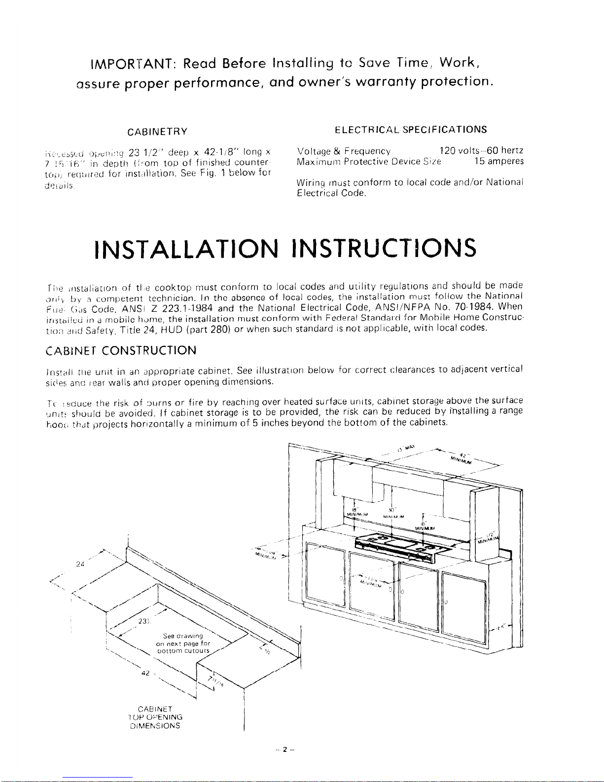
CABINETRY
ELECTRICAL SPECIFICATIONS
!I; ;..rsXU
i)~,t;tll::q 23 112” deep x 42-118” long x
7 ; L-i -, k; ’ ’
in depth (irom top of finished counter
toil; I-ec;:rlrad for Inst~rllation. See Fig. 1 below for
$F:ibllS
Voltdge & Frequency
120 volts--60 hertz
Maximum Protective Device Size
15 amperes
Wirinq must conform to local code and/or National
Electrical Code.
INSTALLATION INSTRUCTI
Tije irlstal;atlorl of tfe cooktop must conform to local codes and utility regulatrons and should be made
(3 I i i , by a competent technician. In the absence of local codes, the installation must follow the National
F , J 2
!;,js Code, ANSI Z 223.1-1964 and the National Electrical Code, ANSI/NFPA No. 70-1984. When
irljtiri/cci in a mobile hume, the installation must conform with Federal Standar-d for Mobile Home Construc-
tion <rid Safety, Title 24, HUD (part 280) or when such standard is not applicable, with local codes.
CABiNE i- CONSTRUCTION
)trs:atl tire urirt in an appropriate cabinet. See itlustratron below for correct clearances to adjacent vertical
sides ano I ear walls and proper opening dimensions.
1. I
! L-ouct: the risk of turns or fire by reaching over heated surface units, cabinet storage above the surface
l.Anit: shouid be avoidetl. If cabinet storage is to be provided, the risk can be reduced by installing a range
hook, thdt projects horrzontally a minimum of 5 inches beyond the bottom of the cabinets.
CAElhET
-I OP Or’ENING
DihlEhiClONS
23:;”
19”
l-9/16"
cm--, 9”
t
4-;15116’
1
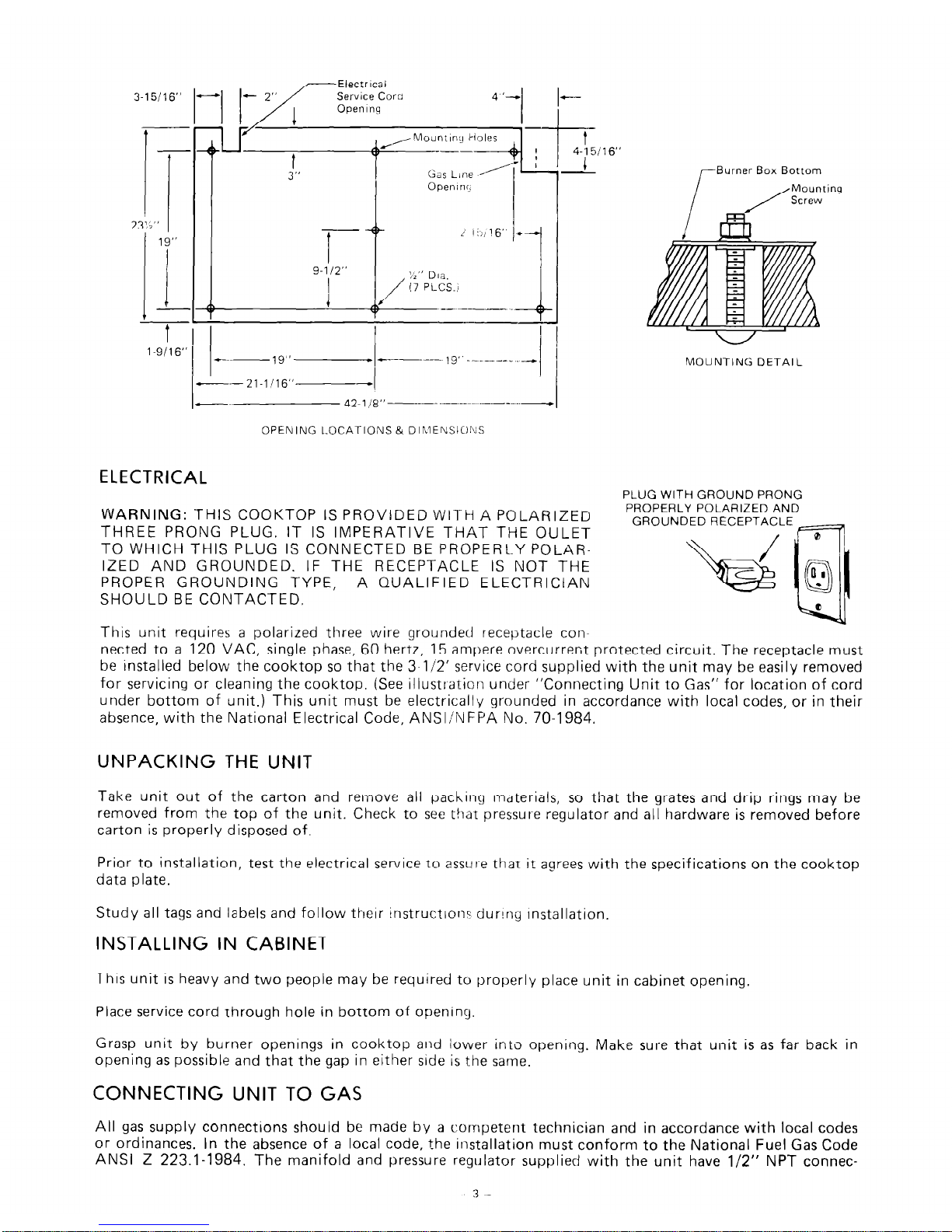
~Burner Box Bottom
MOUNTING DETAIL
OPENING LOCATIONS & DlhlENSIO!VS
ELECTRICAL
PLUG WITH GROUND PRONG
WARNING: THIS COOKTOP IS PROVIDED WITH A POLARIZED
PROPERLY POLARIZED AND
THREE PRONG PLUG. IT IS IMPERATIVE THAT THE OULET
GROUNDED RECEPTACLE
0
TO WHICH THIS PLUG IS CONNECTED BE PR0PERL.Y POLAR-
IZED AND GROUNDED. IF THE RECEPTACLE IS NOT THE
PROPER GROUNDING TYPE, A QUALIFIED ELECTRICIAN
SHOULD BE CONTACTED.
This unit requires a polarized three wire grounded receptacle con-
nected to a 120 VAC, single phase, 60 hertz, 15 ampere overcurrent protected circuit. The receptacle must
be installed below the cooktop so that the 3-l/2’ service cord supplied with the unit may be easily removed
for servicing or cleaning the cooktop. (See illustration under “Connecting Unit to Gas” for location of cord
under bottom of unit.) This unit must be electrically grounded in accordance with local codes, or in their
absence, with the National Electrical Code, ANSI/NFPA No. 70-1984.
UNPACKING THE UNIT
Take unit out of the carton and remove all packing materials, so that the grates and drip rings may be
removed from the top of the unit. Check to see that pressure regulator and all hardware is removed before
carton is properly disposed of.
Prior to installation, test the electrical service to assur-e thaT it agrees with the specifications on the cooktop
data plate.
Study all tags and labels and follow their InstructIon: dur!ny Installation.
INSTALLING IN CABINET
This unit is heavy and two people may be required to properly place unit in cabinet opening.
Place service cord through hole in bottom of opening.
Grasp unit by burner openings in cooktop and lower into opening. Make sure that unit is as far back in
opening as possible and that the gap in either side is the same.
CONNECTING UNIT TO GAS
All gas supply connections should be made by a competent technician and in accordance with local codes
or ordinances. In the absence of a local code, the installation must conform to the National Fuel Gas Code
ANSI Z 223.1-1984. The manifold and pressure regulator supplied with the unit have l/2” NPT connec-
 Loading...