

Page 1
m
GAS BUILT-IN
SINGLE & DOUBLE OVENS
MODEL (single).
KGBS 146s
MODEL (double).
KGBS 246s
INSTALLATION
INSTRUCTIONS
INSTALLER: FINAL CHECK LIST
PLACEMENT OF UNIT
0 1. Properly positioned - level, aligned and square with cabinet opening.
0 2. Anchored securely to cabinet.
cl 3.0
ven must not be placed under countertop or microwave oven.
ELECTRICAL
0 1. Oven properly grounded,
0 2. Polarized three-wire 12OVAC. 15.20Ampere receptacle with 15-20ampere overcurrent
protection provided for service cord connection.
GAS SUPPLY
0 1. Supply line of 3/8” black iron pipe provided,
0 2. Manual gas shutoff valve must be installed in accessible location. Do Not install shutoff valve
behind oven.
0 3. Oven connections must be tested for gas leaks.
OPERATIONAL
[7 1. If used on LP gas, verify that pressure regulator and orifice hoods have been modified for
use with LP gas.
0 2. Oven racks installed and
0 3. Knobs secured in place and rotate freely without rubbing on edge of control panel glass
holes,
0 4. Selector switch functions in all modes.
0 5. All lights function properly.
0 6. Refer to use and care guide to set electronic clock.
0 7. Doors properly adjusted, open and close smoothly.
0 8. Unless instructed to leave for owner, remove all tags, labels and internal packing material.
slide freely in all posttions.
t
0 9. Oven has been wiped clean to remove fingerprints and other smudges.
THANK YOU INSTALLER:
1. Complete Installation Check List.
Leave all literature for customer.
2.
Notify dealer that installation is completed.
3.
FOR DETAILED INSTRUCTIONS, FOLLOW METHODS DESCRIBED IN THIS FOLDER.
Page 2
IMPORTANT: Read Before Installing to Save Time, Work,
assure proper performance, and owner’s warranty protection.
INSTALLATION INSTRUCTIONS
The oven installation must conform with local codes and ordinances and ulility regulations. In the absence of local
codes, installation must conform with American National Standard, National Fuel Gas Code ANSI Z223.1-latest
edition. It is the customer’s responsibility to contact a qualified electrical installer to assure that electrical installation
is adequate and in conformance with National Electrical Code, ANSVNFPA 70-latest edition and local codes and
ordinances.
When installed in a mobile home, the installation must conform to the Manufactured Home Construction and Safety
Standards, Title 24 CFR, Part 3280 (formerly the Federal Standard for Mobile Home Construction and Safety, Title
24, HUD, Part 280).
Fire Hazard
l
Do Not use or store gasoline, paint, thinners and other flammable materials
near oven.
l
Do Not obstruct the flow of combustion and ventilation air.
l
If you smell gas:
1. Open windows.
2. Don’t touch electrical switches.
3. Extinguish any open flame.
4. Immediately call your gas supplier.
Failure to follow these instructions could result in a fire or explosion.
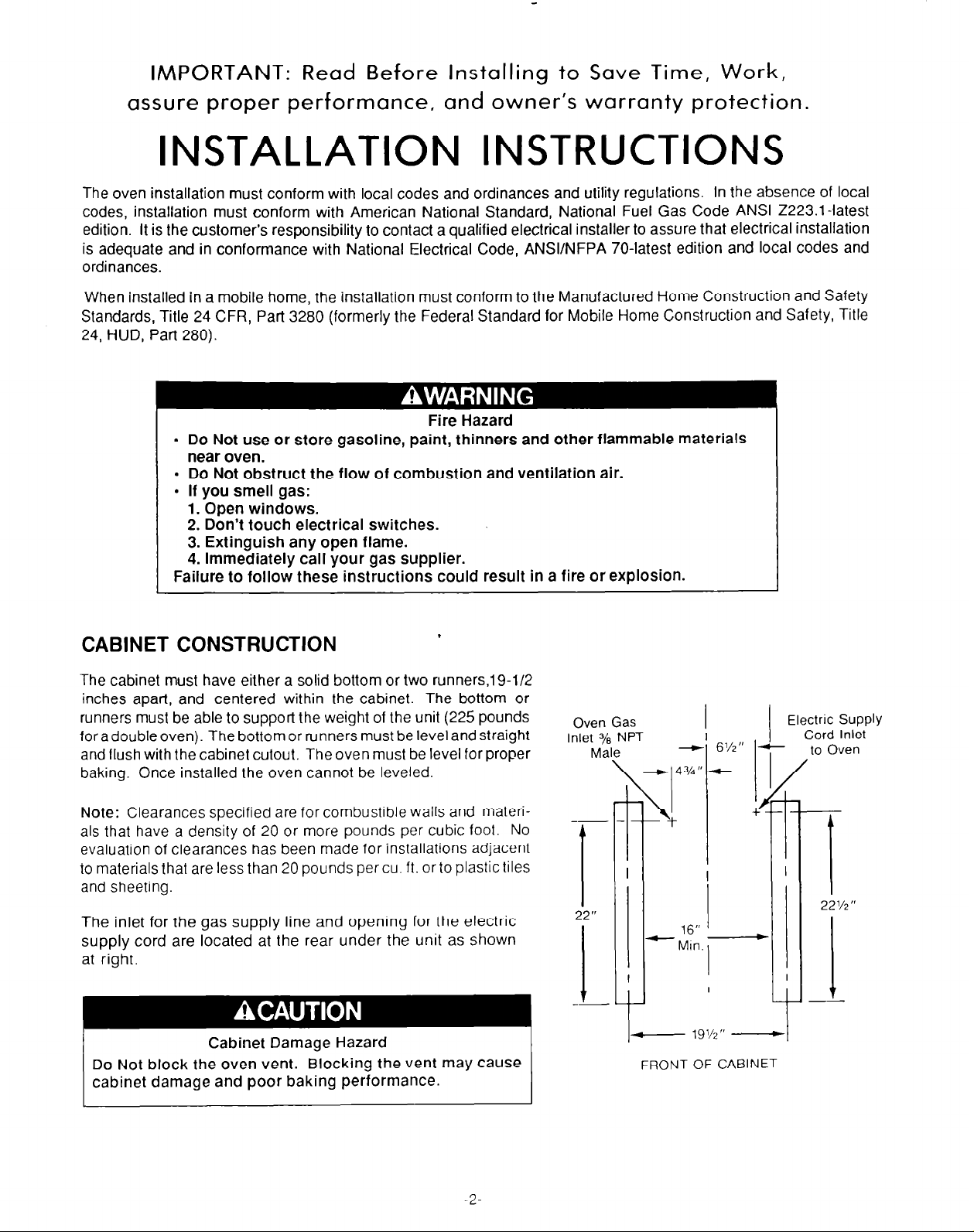
CABINET CONSTRUCTION
The cabinet must have either a solid bottom or two runners,l9-l/2
inches apart, and centered within the cabinet. The bottom or
runners must be able to support the weight of the unit (225 pounds
for a double oven). The bottom or runners must be level and straight
and flush with the cabinet cutout. The oven must be level for proper
baking. Once installed the oven cannot be leveled.
Note: Clearances specified are for combustible walls and materi-
als that have a density of 20 or more pounds per cubic foot. No
evaluation of clearances has been made for installations adjacent
to materials that are less than 20 pounds per cu. ft. or to plastictiles
and sheeting.
The inlet for the gas supply line and opening for the electric
supply cord are located at the rear under the unit as shown
at right.
Cabinet
Do
Not block
cabinet damage and poor baking performance.
the oven vent. Blocking the vent may cause
Damage Hazard
.
Oven Gas
Inlet 3/s NPT
Male
\
-
4
I
- to Oven
+
FRONT OF CABlNET
Electric Supply
Cord Inlet
2-
Page 3
- 24‘ to inside of
back cabinet
2-l/2” MIN
to upper
cab. doors
MIN
- 24” MIN _
I
I
I
- 22-112’MIN -
i
I
l/2- to lower
cab. doors
- 24- to Inside of
cabinet back
-------
Floor
2-112” MIN
to upper
cab. doors _
,
t
9’ MIN
. 1
- 24- MIN -
- 22-112’ MIN
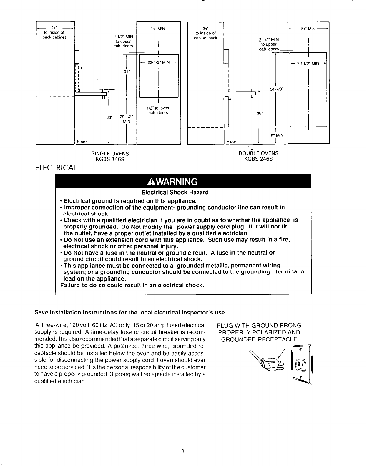
SINGLE OVENS
KGBS 146s
ELECTRICAL
Electrical Shock Hazard
l
Electrical ground is required on this appliance.
. Improper connection of the equipment- grounding conductor line can result in
electrical shock.
l
Check with a qualified electrician if you are in doubt as to whether the appliance is
properly grounded. Do Not modify the power supply cord plug. If it will
the outlet, have a proper outlet installed by a qualified electrician.
l
Do Not use an extension cord with this appliance. Such use may result in a fire,
electrical shock or other personal injury.
- Do Not have a fuse in the neutral or ground circuit. A fuse in the neutral or
ground circuit could result in an electrical shock.
l
This appliance must be connected to a grounded metallic, permanent wiring
system; or a grounding conductor should be connected to the grounding
lead on the appliance.
Failure to do so could result in an electrical shock.
Save Installation Instructions for the local electrical inspector’s use.
DOUiiLE OVENS
KGBS 246s
not
fit
terminal or
A three-wire, 120 volt, 60 Hz, AC only, 15 or20 amp fused electrical
supply is required. A time-delay fuse or circuit breaker is recommended. It is also recommended that a separate circuit serving only
this appliance be provided. A polarized, three-wire, grounded receptacle should be installed below the oven and be easily accessible for disconnecting the power supply cord if oven should ever
need to be serviced. It is the personal responsibility of the customer
to have a properly grounded, 3-prong wall receptacle installed by a
qualified electrician.
-3
PLUG WITH GROUND PRONG
PROPERLY POLARIZED AND
GROUNDED RECEPTACLE
Page 4
UNPACKING THE UNIT
Personal Injury
More than one person is required to lift or
move the oven because of its weight and
size. Failure to follow these instructions
may result in personal injury.
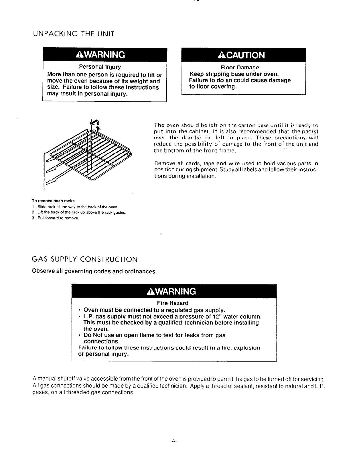
To remove oven racks
1. Slide rack all the way to the back of the oven.
2. Lift the back of the rack up above the rack guides
3. Pull forward to remove.
Floor Damage
Keep shipping base under oven.
Failure to do so could cause damage
to floor covering.
The oven should be left on the carton base until it is ready to
put into the cabinet. It is also recommended that the pad(s)
over the door(s) be left in place. These precautions will
reduce the possibilitv of damaqe to the front of the unit and
the bottom’of the frdnt frame.-
Remove all cards, tape and wire used to hold various parts in
posltion during shipment. Study all labelsand followtheir instruc-
tlons during Installation.
GAS SUPPLY CONSTRUCTION
Observe all governing codes and ordinances.
Fire Hazard
l
Oven must be connected to a regulated gas supply.
l
L-P. gas supply must not exceed a pressure of 12” water column.
This must be checked by a qualified technician before installing
the oven.
l
Do Not use an open flame to test for leaks from gas
connections.
Failure to follow these instructions could result in a fire, explosion
or personal injury.
A manual shutoff valve accessible from the front of the oven is provided to permit the gas to be turned off for servicing.
All gas connections should be made by a qualified technician. Apply a thread of sealant, resistant to natural and L.P.
gases, on all threaded gas connections.
Page 5

INSTALLING THE UNIT IN CABINET
Route electric supply cord so that it can be plugged into
receptacle after unit has been slid into place in cabinet.
Potential Personal Injury
l
Use both hands to remove oven doors.
l
Grasp only the sides of the oven door. Do Not use any
portion of the front frames or trim for lifting.
Failure to properly grasp oven door could result in
damage to product or personal injury.
The doors should be removed to decrease the weight of the
oven and provide a better hand hold on the oven while lifting
it into the cabinet.
A.
TO REMOVE
Use caution! Oven door is heavy.
1. Open door completely.
2. Depress finger tab in oven door hinge area. Push tab
toward oven. Lift tab away from door liner and slide toward
top of oven door.
3. Repeat step 2 for other side of door.
4. Close door until approximately 5 inches from fully closed
position.
5. Slide door off the hinge arm assemblies.
6. Repeat steps 1 through 5 for other door on double ovens.
DOORS (See Illus.)
DOOR REMOVE
BE SURE THAT
ARE IN PLACE TO PROVIDE PROPER AIR FLOW BETWEEN
CABINET AND OVEN.
When oven has been placed into cabinet, the bottom trim strip
is placed on the lower edge of the front frame. This is done
by loosening the three screws at the bottom of the front frame.
Place gas valve extension rod through hole in trim strip and
slide strip under screw heads until the top edge of trim meets
the lower corners of the front frame (see Illus.). Tighten screws
to hold trim to front frame. Make sure that valve is turned to
the full “on” position (pin straight and down).
MICA SPACERS AT EITHER SIDE OF OVEN
Personal Injury Hazard
Securely fasten wall oven to cabinets using the screws
provided (4 screws for a double oven or 2 screws for a
single oven). Failure
or
tip during
use and result in personal injury.
to do so could cause oven to move
Secure oven to cabinet with #8 screws provided. Do not
overtighten screws. Edge of front frame should be parallel
to cabinet. Disregard any excess screws that are left after
all screw holes in front frame have been used.
FINGER TAB
B. REPLACE OVEN RACKS IN OVEN CAVITY.
C. REINSTALL THE DOOR(S) (See Illus.)
1. Slide door hinge arms until firmly seated.
2. Lower door to full open position.
3. Push finger tabs to back. Depress the tabs and slide forward.
4. Close and reopen door slowly to make sure it has been replaced properly.
5. Repeat steps 1 through 4 for other door on double oven.
Page 6

CHECKOUT AND ADJUSTMENT
After the oven is installed and the gas connected, all gas connections MUST be tested for gas leaks. Be sure that electricity is off before turning on the gas supply. Test with pressure gauge or apply soapy solution or leak detector solution
on ALL gas connections. Repair any leaks that may appear before operating oven.
THE REGULATOR IS SET FOR USE WITH NATURAL GAS. FOR USE WITH LP GAS, THE REG-
ULATOR MUST BE CONVERTED. The gas pressure regulator is located in the compartment behind the
control frame. Removecontrol frame (see instructions below), loosen and slide the control mounting plate
out to gain access to the pressure regulator.
TO REMOVE CONTROL FRAME
t
(TYPICAL CONSOLE)
1
Remove bezel nut from oven light switch by turning
2. Remove all other knobs by pullrng straight forward,
3. Remove front 3 Phillips screws under control frame and 2 Phillips screws on top portlon of control
frame. Be sure to hold control frame in place.
4. Pull control frame forward.
counterclockwrse
v
To convert the regulator for LP gas, remove the regulator access cap (see below). Reverse cap, so that “LP” In
cap recess is showing when cap is in place. Return cap to regulator and tighten. The regulator
column (W-C.) for use with natural gas and 10” W.C. for use with LP gases. In order to check pressure
regulator, the inlet test pressure must be at least one (1”) W.C. greater (5” for natural and 1 1” for LP) than
setting. Maximum pressure to regulator must not exceed 14” W.C.
IS
set at 4” water
\
PRESSURE REGULATOR
(TYPICAL)
6-
Page 7

The appliance and Its individual shutoff valve must be disconnected from the gas supply piping system
during any pressure testing of that system at test pressures in excess of % psig.
The appliance must be isolated from the gas supply piping system by closing its individual manual shutoff
valve during any pressure testing of the gas supply piping system at test pressures equal to or less than %
psig.
This unit may be used on natural or LP gas. A basic adjustment has been made at the factory for natural
gas.
WHEN USED WITH LP GASES: MAKE CERTAIN THAT PRESSURE REGULATOR HAS BEEN
CONVERTED FOR USE WITH LP GAS. ADJUST BURNER INPUT BY TURNING OUTER ORlFtCE
HOODS DOWN UNTIL SNUG AGAINST INNER ORIFICE NEEDLE.
Final adjustment of the air-gas mixture is made by turning the air shutter until a concise blue cone has
been obtained. If the flames lift from the burner, reduce the air opening in the shutter. If the flames are
yellow, increase the air shutter opening.
DOOR ADJUSTMENT CHECK
NEWSPAPER STRIPS
TOP OF DOOR
STRIPS
Place2’x 18”stripsofnewspaperin locarlons
indicated by illustration. Allow one end of the
paper to extend into the oven caviry. Pull
gently at each piece of paper. If door IS
properly adjusted. each piece of paper will
offer firm resistancewhen pulled. When door
I
~sourof adjustment. slide unitout farenough
IO expose hinges on each side (see preceding page). Loosen screws and move bottom
of door to a proper fit. After completing adjustment tighten all screws in hinges.
NEFI;K
SIDE OF
DOOR
NEWSPAPER STRIPS
BOTTOM OF DOOR
NEWSPAPER
SIDE OF DOOR
*
ADJUST IN
OR OUT FOR
, PROPER DOOF
SEAL-
-v
ADJUST UP OR DOWN‘V
TO ALIGN DOOR
Note: If the oven is installed on a solid bottom, the gas supply must be disconnected before the oven can be slid
forward to adjust doors.
Page 8

c”u”yu; OVEN LIGHT
>
INCI
SWITCH
- -
”
Ir-
El
= ELECTRONIC =
CLOCK
12V RELAY
ROTISSERIE
MOTOR
BAN
SCHEMATIC DIAGRAM
KGBS14BSBLO
KGBS24BSBLO
U.O.
LIGHT
L.O.
LIGHT
U.O. IND.
LIGHT
BAKE IGNITOR BAKE VALVE
BROIL IGNITOR
BROIL VALVE
I --------------------- ~~~-~~~~~~~-~~-----------------
x3--?&
0~x~x~0~x~x
CLOSED
0 = OPEN
LOWER OVEN
3 2
FAN
IND LIGHT
L 0 IND
LIGHT
BAKE IGNITOR
WARNING
DISCONNECT FROM ELECTRICAL
SUPPLY BEFORE SERVICING UNIT
BLOWER
MOTOR
BAKE VALVE
-8-
Page 9

POWER ON
IN).
WHT
OVEN IN)
LIWT
YEI
LK
1r
CAP
RED
WHT
MEAT PROBE JACK
I
S IWGL E OVEN HOOKUP
KGBSl46SBLO
YEL
SERVICE COi(3
Page 10

W”T
II ’
J GUN
1 I
POWER Oh
IN).
,BAKE VALVE
BLU
MECT PROBE JACK
‘WH T
16L
U/O BROIL ICNITOR
WHT
, CLK
u-0. IN).
LIWT
ELECTRONIC
//
\
U/G BAKE lGNlTCR
EOUB i E OVEN HOCKUF
KGbS233SBi0
-lO-
DiSCCrddECT FROM ELECTRICAL
SIJPFLY BEFORE SERVlCIr~IG UNIT
Page 11

Part No. 3177319 Rev C
(C) 1989 KitchenAid, Inc.
Prepared by KitchenAid, St. Joseph, Michigan 49085
.ll
Printed in U.S.A
 Loading...