

KitchenAid GY398LXPT01, GY398LXPS01, GY398LXPS03, GY398LXPS04, GY398LXPQ03 Installation Guide
...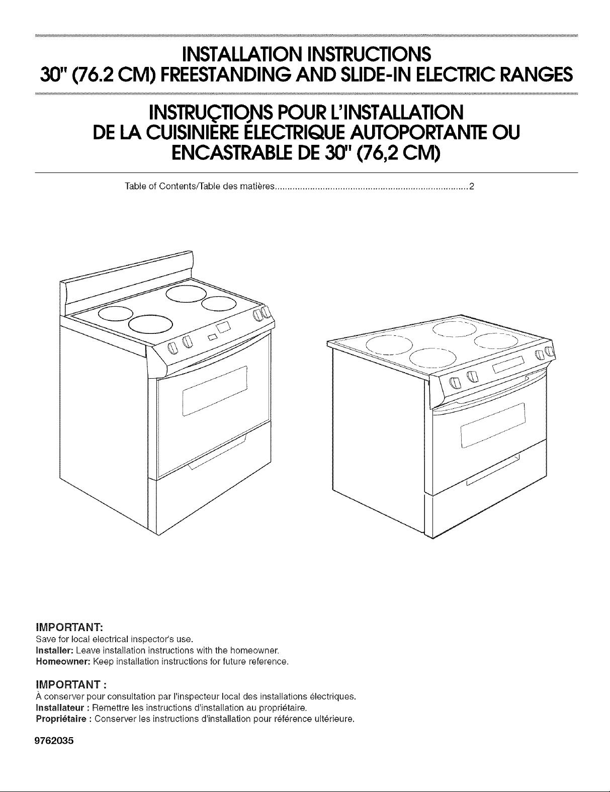
INSTALLATIONINSTRUCTIONS
30"(76.2 CM) FREESTANDINGAND SLIDE-INELECTRICRANGES
INSTRUCTIONSPOURL'INSTALLATION
DELA CUISINIEREELECTRIQUEAUTOPORTANTEOU
ENCASTRABLEDE30"(76,2 CM)
Table of Contents/Table des matieres ............................................................................. 2
iMPORTANT:
Save for local electrical inspector's use.
Installer: Leave installation instructions with the homeowner.
Homeowner: Keep installation instructions for future reference.
iMPORTANT :
,&,conserver pour consultation par I'inspecteur local des installations electriques.
Instaliateur : Remettre les instructions d'installation au proprietaire.
Proprietaire : Conserver les instructions d'installation pour r6ference ulterieure.
9762035
TABLEOF CONTENTS
TABLEDESMATIERES
RANGE SAFETY ............................................................................. 3
INSTALLATION REQUIREMENTS ................................................ 4
Tools and Parts ............................................................................ 4
Location Requirements ................................................................ 4
Electrical Requirements - U.S.A. Only ......................................... 7
Electrical Requirements - Canada Only ....................................... 8
Countertop Preparation ............................................................... 8
INSTALLATION INSTRUCTIONS .................................................. 9
Unpack Range .............................................................................. 9
Install Anti-Tip Bracket ................................................................. 9
Optional Rear Spacer Cover ...................................................... 10
Electrical Connection - U.S.A. Only ........................................... 10
Verify Anti-Tip Bracket Location ................................................ 13
Level Range ................................................................................ 14
Complete Installation ................................................................. 14
Moving the Range ...................................................................... 14
ANTI-TIP BRACKET TEMPLATE ................................................ 23
SECURITI :!:DE LA CUISINI_RE .................................................... 15
EXIGENCES D'INSTALLATION ................................................... 16
Outillage et pieces ...................................................................... 16
Exigences de I'emplacement d'installation ............................... 16
Specifications de I'installation electrique -
Canada seulement ..................................................................... 19
Preparation du plan de travail .................................................... 19
INSTRUCTIONS D'INSTALLATION ............................................. 20
Deballage de la cuisiniere .......................................................... 20
Installation de la bride antibasculement .................................... 20
Obturation de I'espace a I'arriere (option) .................................. 21
Verification de I'emplacement de la bride anti-basculement ....21
Mise a niveau de la cuisiniere .................................................... 22
Achever I'installation .................................................................. 22
Deplacement de la cuisiniere ..................................................... 22
GABARIT POUR LA BRIDE ANTIBASCULEMENT .................... 23
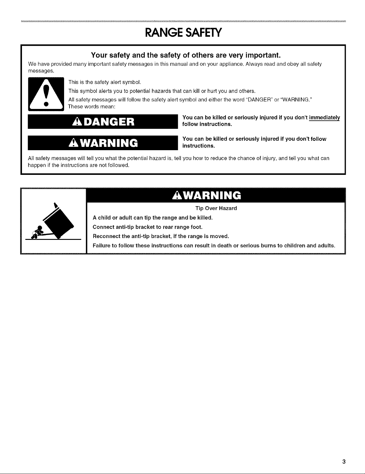
RANGESAFETY
Your safety and the safety of others are very important.
We have provided many important safety messages in this manual and on your appliance. Always read and obey all safety
messages.
This is the safety alert symbol.
This symbol alerts you to potential hazards that can kill or hurt you and others.
All safety messages will follow the safety alert symbol and either the word "DANGER" or "WARNING."
These words mean:
You can be killed or seriously injured if you don't immediately
follow instructions.
You can be killed or seriously injured if you don't follow
instructions.
All safety messages will tell you what the potential hazard is, tell you how to reduce the chance of injury, and tell you what can
happen if the instructions are not followed.
A child or adult can tip the range and be killed.
Connect anti-tip bracket to rear range foot.
1_ 1 Tip Over Hazard
Reconnect the anti=tip bracket, if the range is moved.
Failure to follow these instructions can result in death or serious burns to children and adults.
INSTALLATIONREQUIREMENTS
s end Pcstts
Gather the required tools and parts before starting installation.
Read and follow the safety instructions provided with any tools
listed here.
Tools needed
• Tape measure • %" drive rachet
• Flat-blade screwdriver • 1A" nut driver
• Level • %6" nut driver
• Hammer • 1/8"(3.2 mm) drill bit (for
• Hand or electric drill wood floors)
• Channel lock pliers • 3/16"(4.8 mm) carbide-tipped
• Marker or pencil concrete/ceramic floors)
• Masking tape
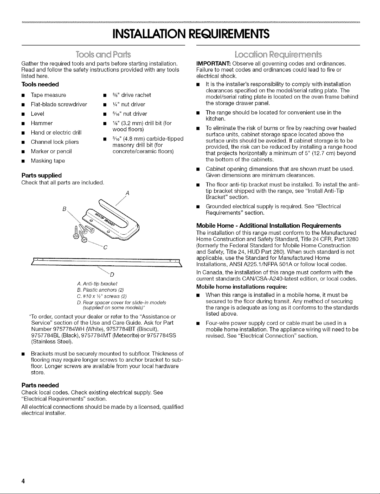
Parts supplied
Check that all parts are included.
masonry drill bit (for
A
IMPORTANT: Observe all governing codes and ordinances.
Failure to meet codes and ordinances could lead to fire or
electrical shock.
• It is the installer's responsibility to comply with installation
clearances specified on the model/serial rating plate. The
model/serial rating plate is located on the oven frame behind
the storage drawer panel.
• The range should be located for convenient use in the
kitchen.
To eliminate the risk of burns or fire by reaching over heated
surface units, cabinet storage space located above the
surface units should be avoided. If cabinet storage is to be
provided, the risk can be reduced by installing a range hood
that projects horizontally a minimum of 5" (12.7 cm) beyond
the bottom of the cabinets.
• Cabinet opening dimensions that are shown must be used.
Given dimensions are minimum clearances.
• The floor anti-tip bracket must be installed. To install the anti-
tip bracket shipped with the range, see "Install Anti-Tip
Bracket" section.
• Grounded electrical supply is required. See "Electrical
Requirements" section.
A.Anti-tip bracket
B.Plastic anchors (2)
C. #10x V2"screws (2)
D. Rearspacer cover forslide-in models
(supplied onsome models)*
*To order, contact your dealer or refer to the "Assistance or
Service" section of the Use and Care Guide. Ask for Part
Number 9757784WH (White), 9757784BT (Biscuit),
9757784BL (Black), 9757784MT (Meteorite) or 9757784SS
(Stainless Steel).
Brackets must be securely mounted to subfloor. Thickness of
flooring may require longer screws to anchor bracket to sub-
floor. Longer screws are available from your local hardware
store.
Parts needed
Check local codes. Check existing electrical supply. See
"Electrical Requirements" section.
All electrical connections should be made by a licensed, qualified
electrical installer.
Mobile Home - Additional Installation Requirements
The installation of this range must conform to the Manufactured
Home Construction and Safety Standard, Title 24 CFR, Part 3280
(formerly the Federal Standard for Mobile Home Construction
and Safety, Title 24, HUD Part 280). When such standard is not
applicable, use the Standard for Manufactured Home
Installations, ANSI A225.1/NFPA 501A or follow local codes.
In Canada, the installation of this range must conform with the
current standards CAN/CSA-A240-1atest edition, or local codes.
Mobile home installations require:
• When this range is installed in a mobile home, it must be
secured to the floor during transit. Any method of securing
the range is adequate as long as it conforms to the standards
listed above.
• Four-wire power supply cord or cable must be used in a
mobile home installation. The appliance wiring will need to be
revised. See "Electrical Connection" section.
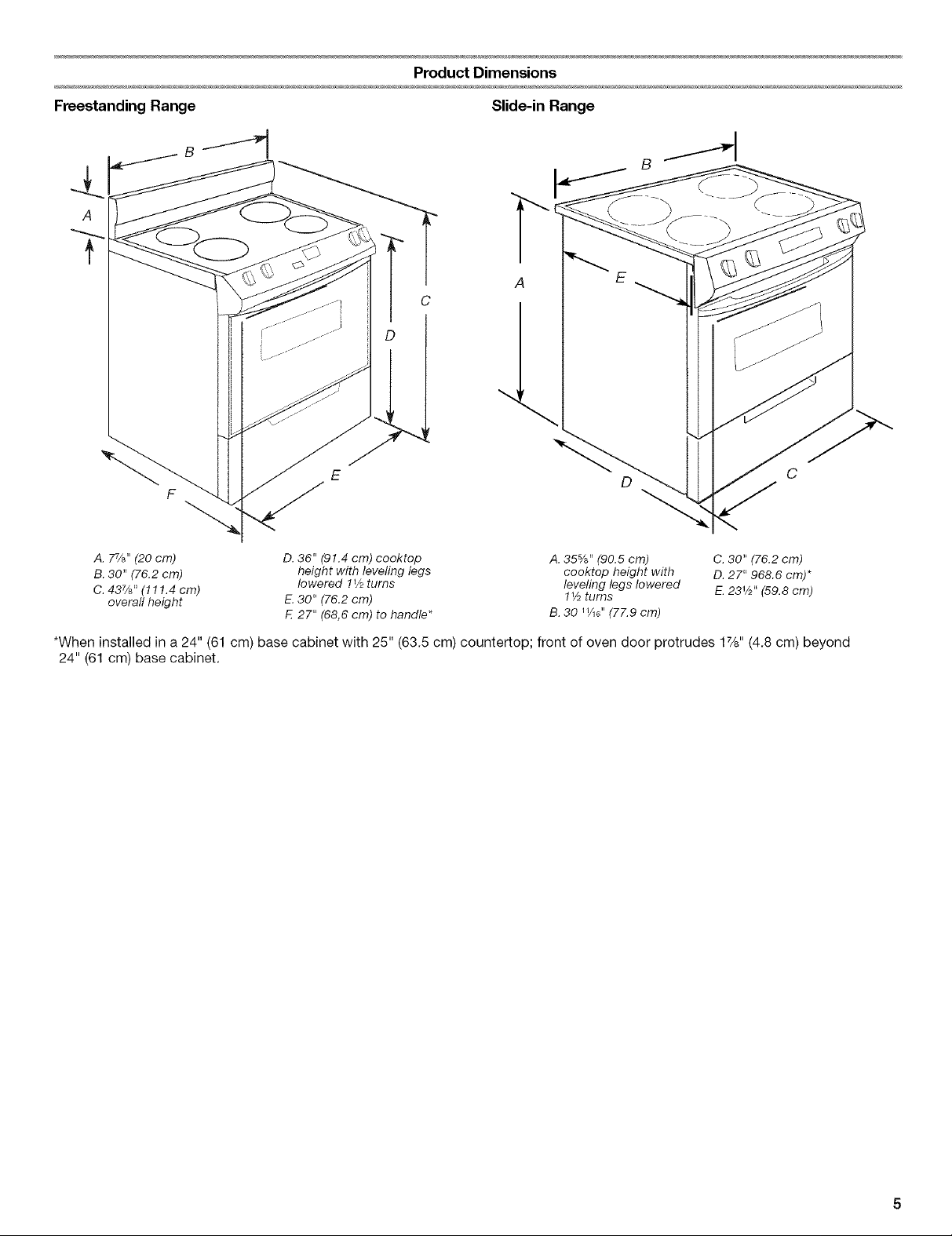
Product Dimensions
Freestanding Range Slide-in Range
A
A
C
C
A. 7%" (20 cm)
B. 30" (76.2 cm)
C. 437/_'' (! 11.4 cm)
overall height
E
D. 36" (91.4 cm) cooktop
height with leveling legs
lowered 1V2turns
E.30" (76.2 ore)
E 27" (68,6 cm) to handle*
D
A. 35%" (90.5 cm)
cooktep height with
leveling legs lowered
1V2turns
B. 30 W_e"(77.9 cm)
C. 30" (76.2 Cm)
D. 27" 968.6 cm)*
E. 23V2" (59.8 cm)
*When installed in a 24" (61 cm) base cabinet with 25" (63.5 cm) countertop; front of oven door protrudes 1%" (4.8 cm) beyond
24" (61 cm) base cabinet.
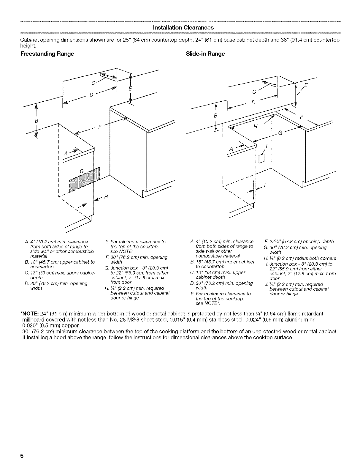
Installation Clearances
Cabinet opening dimensions shown are for 25" (64 cm) countertop depth, 24" (61 cm) base cabinet depth and 36" (91.4 cm) countertop
height.
Freestanding Range Slide-in Range
B
\
\
9
A. 4" (10.2 cm) min. clearance
from both sides of range to
side wall or other combustible
material
B. 18" (45.7 cm) upper cabinet to
countertop
C. !3" (33 cm) max. upper cabinet
depth
D.30" (76.2 cm) min. opening
width
B F
E. For minimum clearance to A. 4" (10.2 cm) min. clearance F. 223/4``(57.8 cm) opening depth
the top of the cooktop, from both sides of range to G. 30" (76.2 cm) min. opening
see NOTE _. side wall or other width
F. 30" (76.2 cm) min. opening combustible material H. V4"(6.2 cm) radius both comers
width B. 18" (45.7 cm) upper cabinet I. Junction box - 8" (20.3 cm) to
G. Junction box - 8" (20.3 cm) to countertop 22" (55.9 cm) from either
to 22" (55.9 cm) from either C. 13" (33 cm) max. upper cabinet, 7" (17.8 cm) max. from
cabinet, 7" (17.8 cm) max. cabinet depth door
from door D. 30" (76.2 cm) min. opening J. 7/8"(2.2 cm) min. required
H. 7/8"(2.2 cm) min. required width between cutout and cabinet
between cutout and cabinet E.For minimum clearance to door or hinge
door or hinge the top of the cooktop,
see NOTE*
*NOTE: 24" (61 cm) minimum when bottom of wood or metal cabinet is protected by not less than 1/4"(0.64 cm) flame retardant
millboard covered with not less than No. 28 MSG sheet steel, 0.015" (0.4 mm) stainless steel, 0.024" (0.6 mm) aluminum or
0.020" (0.5 mm) copper.
30" (76.2 cm) minimum clearance between the top of the cooking platform and the bottom of an unprotected wood or metal cabinet.
If installing a hood above the range, follow the instructions for dimensional clearances above the cooktop surface.
Ifcodespermitandaseparategroundwireisused,itis
recommendedthataqualifiedelectricalinstallerdeterminethat
thegroundpathandwiregaugeareinaccordancewithlocal
codes.
Ifcodespermitandaseparategroundwireisused,itis
recommendedthataqualifiedelectriciandeterminethatthe
groundpathisadequate.
Donotuseanextensioncord.
Besurethattheelectricalconnectionandwiresizeareadequate
andinconformancewiththeNationalElectricalCode,ANSI/
NFPA70-latesteditionandalllocalcodesandordinances.
Acopyoftheabovecodestandardscanbeobtainedfrom:
NationalFireProtectionAssociation,
OneBatterymarchPark,
Quincy,MA02269
Electrical Connection
To properly install your range, you must determine the type of
electrical connection you will be using and follow the instructions
provided for it here.
• Range must be connected to the proper electrical voltage
and frequency as specified on the model/serial number rating
plate. (The model/serial number rating plate is located on the
oven frame behind the storage drawer panel.)
When a 4-wire or 3-wire, single phase 120/240 volt, 60 Hz,
AC only electrical supply is available, a 50-amp maximum
circuit protection is required (or, if specified on the model/
serial rating plate, when a 4-wire or 3-wire single phase
120/208 volt 60 Hz, AC only electrical supply is available, a
40-amp maximum circuit protection is required), fused on
both sides of the line.
• A time-delay fuse or circuit breaker is recommended.
The range can be connected directly to the fused disconnect
(or circuit breaker box) through flexible, armored or
nonmetallic sheathed, copper or aluminum cable. See
"Electrical Connection."
Allow 2 to 3 ft of slack in the line so that the range can be
moved if servicing is ever necessary.
A UL listed conduit connector must be provided at each end
of the power supply cable (at the range and at the junction
box).
• Wire sizes and connections must conform with the rating of
the range (40 amps).
• The wiring diagram is located on the underside of the storage
drawer or below the warming drawer in a clear plastic bag.
If connecting to a 4-wire system:
This range is manufactured with the ground connected to the
cabinet. The ground must be revised so the green ground wire of
the 4-wire power supply cord is connected to the cabinet. See
"Electrical Connection."
Grounding through the neutral conductor is prohibited for new
branch-circuit installations (1996 NEC); mobile homes; and
recreational vehicles, or an area where local codes prohibit
grounding through the neutral conductor.
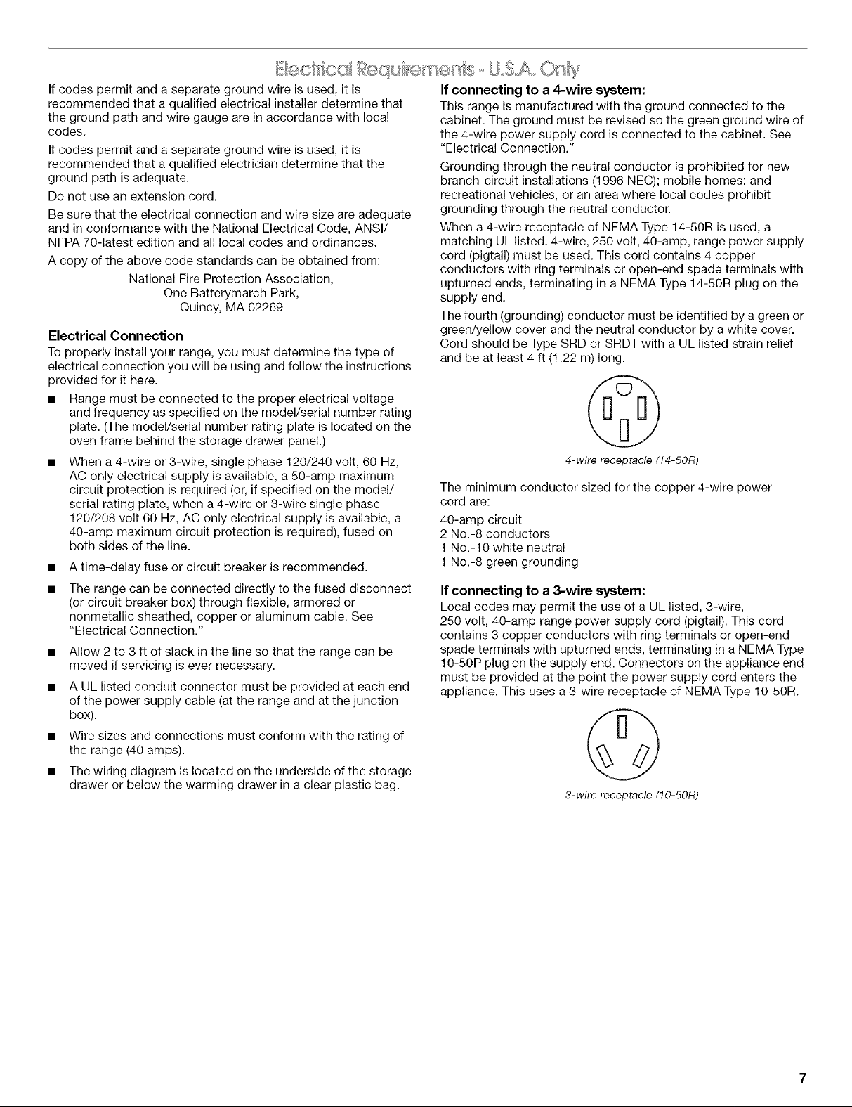
When a 4-wire receptacle of NEMA Type 14-50R is used, a
matching UL listed, 4-wire, 250 volt, 40-amp, range power supply
cord (pigtail) must be used. This cord contains 4 copper
conductors with ring terminals or open-end spade terminals with
upturned ends, terminating in a NEMA Type 14-50R plug on the
supply end.
The fourth (grounding) conductor must be identified by a green or
green/yellow cover and the neutral conductor by a white cover.
Cord should be Type SRD or SRDT with a UL listed strain relief
and be at least 4 ft (1.22 m) long.
4-wire receptacle (14-50R)
The minimum conductor sized for the copper 4-wire power
cord are:
40-amp circuit
2 No.-8 conductors
1 No.-10 white neutral
1 No.-8 green grounding
If connecting to a 3-wire system:
Local codes may permit the use of a UL listed, 3-wire,
250 volt, 40-amp range power supply cord (pigtail). This cord
contains 3 copper conductors with ring terminals or open-end
spade terminals with upturned ends, terminating in a NEMA Type
10-50P plug on the supply end. Connectors on the appliance end
must be provided at the point the power supply cord enters the
appliance. This uses a 3-wire receptacle of NEMA Type 10-50R.
3-wire receptacle (10-50R)
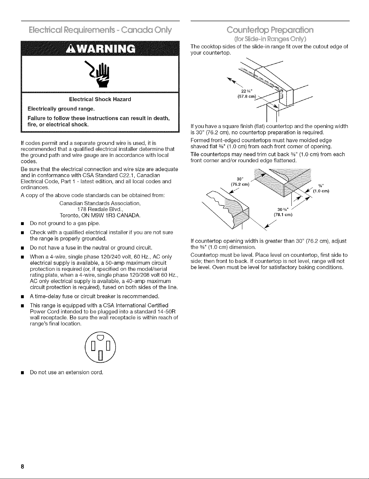
The cooktop sides of the slide-in range fit over the cutout edge of
your countertop.
Electrical Shock Hazard
Electrically ground range.
Failure to feiow these instructions can result in death,
fire, or electrical shock.
If codes permit and a separate ground wire is used, it is
recommended that a qualified electrical installer determine that
the ground path and wire gauge are in accordance with local
codes.
Be sure that the electrical connection and wire size are adequate
and in conformance with CSA Standard C22.1, Canadian
Electrical Code, Part 1 - latest edition, and all local codes and
ordinances.
A copy of the above code standards can be obtained from:
Canadian Standards Association,
178 Rexdale Blvd.,
Toronto, ON M9W 1R3 CANADA.
• Do not ground to a gas pipe.
• Check with a qualified electrical installer if you are not sure
the range is properly grounded.
• Do not have a fuse in the neutral or ground circuit.
When a 4-wire, single phase 120/240 volt, 60 Hz., AC only
electrical supply is available, a 50-amp maximum circuit
protection is required (or, if specified on the model/serial
rating plate, when a 4-wire, single phase 120/208 volt 60 Hz.,
AC only electrical supply is available, a 40-amp maximum
circuit protection is required), fused on both sides of the line.
• A time-delay fuse or circuit breaker is recommended.
This range is equipped with a CSA International Certified
Power Cord intended to be plugged into a standard 14-50R
wall receptacle. Be sure the wall receptacle is within reach of
range's final location.
22 sA"
(s7.8om_ i
If you have a square finish (flat) countertop and the opening width
is 30" (76.2 cm), no countertop preparation is required.
Formed front-edged countertops must have molded edge
shaved flat 3/8"(1.0 cm) from each front corner of opening.
Tile countertops may need trim cut back 8/8"(1.0 cm) from each
front corner and/or rounded edge flattened.
\
If countertop opening width is greater than 30" (76.2 cm), adjust
the %" (1.0 cm) dimension.
Countertop must be level. Place level on countertop, first side to
side; then front to back. If countertop is not level, range will not
be level. Oven must be level for satisfactory baking conditions.
@
• Do not use an extension cord.
 Loading...