

Page 1
KITCHENAID
ELECTRONIC
RANGE
CONTROLS
“B” & “D” LINE WALL OVENS
JOB AID
Part No. 4317169
Page 2

FORWARD
This Job Aid is a reference guide for the experienced technician. It is not
designed as a replacement to basic training, and does not replace the Service Manual or the Use and Care Guide.
OBJECTIVE
The objective of this Job Aid is to allow the experienced appliance technician to become familiar with the operation of the KitchenAid Electronic Range
Control. This Job Aid follows the instructions contained on the companion
training disk, and is designed as reference material.
WHIRLPOOL CORPORATION assumes no responsibility for any repair
made on our products by anyone other than Authorized Factory Service Technicians.
Copyright 1995 Whirlpool Corporation
- ii -
Page 3

Table of Contents
KitchenAid Electronic Range Controls—“B” Line Slide-In..................................................... Page 2
KitchenAid Electronic Range Controls—“B” Line Freestanding ........................................... Page 4
KitchenAid Electronic Range Controls—“B” Line Freestanding/Slide-In ............................ Page 6
KitchenAid Electronic Range Controls—“D” Line Wall Ovens .............................................. Page 7
Reading The Graphic Display.................................................................................................. Page 12
KitchenAid Electronic Range Controls—“Easy Convect” ....................................................Page 13
KitchenAid Electronic Range Controls—“Easy Convect (Meats)”...................................... Page 14
KitchenAid Electronic Range Controls—“Sabbath Mode” ................................................... Page 23
KitchenAid Electronic Range Controls—“Clean Mode” .......................................................Page 32
- iii -
Page 4

— NOTES —
- iv -
Page 5
Important Safety Information
WARNING
This manual is intended for factory-service technicians only. We recommend that customers DO NOT
service their own units, because of the complexity and risk of high-voltage electrical shock.
The following information is used throughout this manual, and should be read carefully.
NOTE
Helpful information that explains a more complicated step, prior to carrying it out .
CAUTION
Information that will help you avoid actions that
could cause product damage (scratches, dents,
etc.) and damage to personal property.
WARNING
Information that alerts you to potentially dangerous conditions. These conditions can cause
serious personal injury (burns, fire and electrical
shock, etc.) if the suggested procedures are not
observed.
Fire Hazard
Do not obstruct the flow of ventilation air.
Electrical Shock Hazard
It is the customer’s responsibility to:
• Contact a qualified electrical installer.
• Assure that electrical installation is adequate
and in conformance with the National Electrical Code, ANSI/NFPA 70—latest edition*,
and all local codes and ordinances.
Failure to do so could result in fire, electrical
shock, or other personal injury.
Take special care when drilling holes into the
wall for venting or electrical wiring. Electrical
wires may be concealed behind the wall covering.
Failure to do so could result in fire, electrical
shock, or other personal injury.
* National Fire Protection Association
Batterymarch Park
Quincy, Massachusetts 02269
BILITY FOR ANY REPAIRS MADE ON OUR PROD-
UCTS BY ANYONE OTHER THAN AUTHORIZED
ASSUMES NO RESPONSI-
SM
SERVICE TECHNICIANS.
- 1 -
Page 6
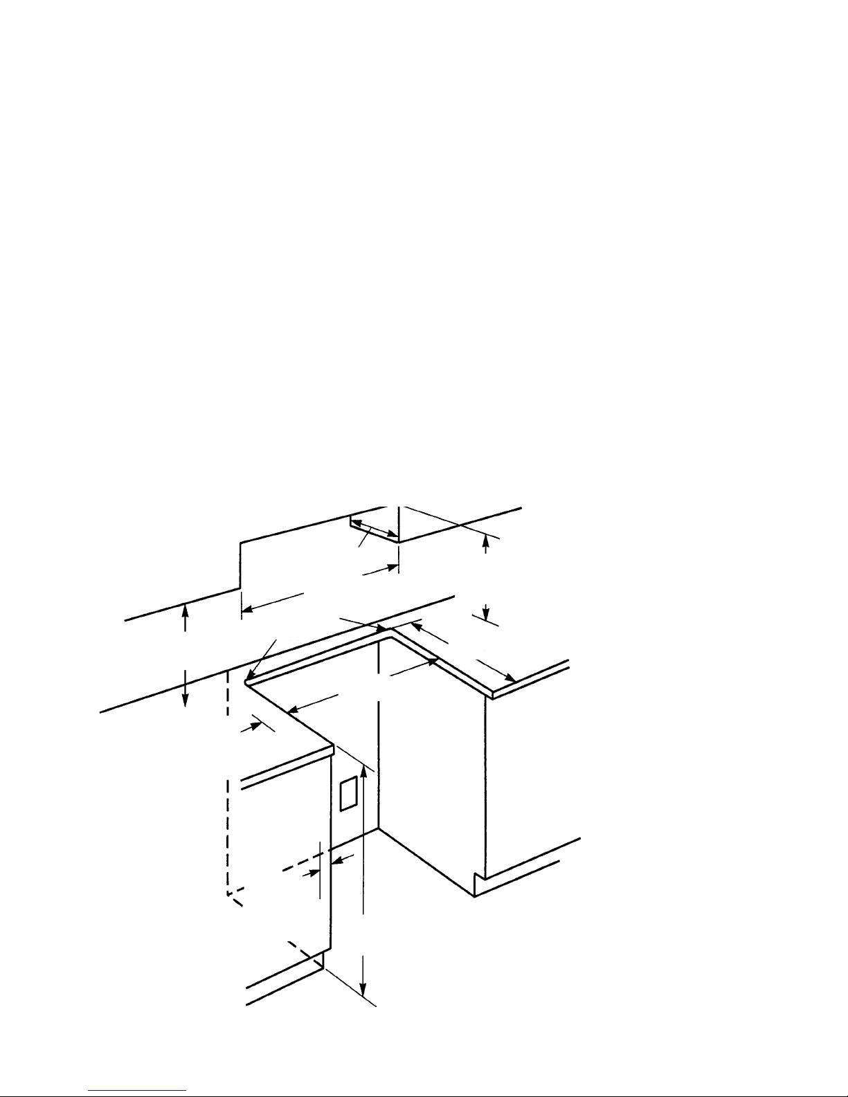
Installation Layout
SLIDE-IN ELECTRIC RANGES
Refer to Figure 1 while you read the following
installation information.
Proper installation is your responsibility. A qualified technician must install this range. Make sure
you have everything necessary for correct installation. It is the responsibility of the installer to comply
with the installation clearances specified on the
serial/rating plate. This plate is located behind the
oven door at the top of the left front frame. IMPOR-
TANT: Be sure to observe all governing codes and
ordinances.
Clearance Note:
A clearance of 30" (76.2 cm)
minimum is required when the bottom of a wood or
metal cabinet is protected by not less than
1
/4" of
flame-retardant millboard covered with not less
"
(33 cm)
13
max. upper
cabinet depth
"
(76.2 cm) min.
30
cabinet opening width
1
/2" (1.3 cm)
radius for both
"
(45.7 cm)
18
upper cabinet to
countertop
4" (10.2 cm) min.
clearance to side
wall or other combustible material on
both sides of the
range.
corners
3
/8" (77.2 cm) min.
30-
opening width
Wall receptacle is
8" (2-.3 cm) to 22"
(55.9 cm) from
either cabinet.
7" (17.8 cm) max.
from floor.
than #28 MSG sheet steel, 0.015" stainless steel,
0.024
"
aluminum, or 0.020" copper. A minimum
clearance of 36
"
(91.4 cm) between the top of the
cooking platform and the bottom of an unprotected
wood or metal cabinet is required.
The cutout shown is for a 25
with a 24
"
(61 cm) base cabinet and no backsplash.
"
(63.5 cm) countertop
The maximum depth for overhead cabinets is 13
(33 cm). For the minimum vertical clearance between the cooking surface and the overhead cabinets, see the previous “Clearance Note.” Overhead cabinets installed at either side of the range
must be a minimum of 18
"
(45.7 cm) above the
cooking surface. The minimum horizontal distance
between the overhead cabinets is 30
The Anti-Tip bracket MUST be
installed.
Refer to
“Clearance
Note” above.
3
/4" (57.8 cm)
22-
opening depth
The range should be located away
from strong draft areas, such as
windows, doors, and strong heating vents or fans. The range should
be located for convenient use in
the kitchen. Recessed installations
must provide complete enclosure
of the sides and rear of the range.
All openings in the wall or floor
where the range is to be installed
must be sealed.
Do not pinch the power cord between the range and the wall when
you push the range into its mounting location.
The shaded area shown in the illustration is the recommended area
for a 120-VAC outlet on the rear
wall and area for a through-thewall connection for gas pipe and
shutoff valve.
"
(76.2 cm).
"
7
/8" (2.2 cm)
min. required
between cutout
and cabinet door
or hinge.
"
(91.4 cm)
36
countertop
height
A grounded electrical outlet is required for this range.
FIGURE 1
Dimensions For Installing The Slide-In
Electric Range
- 2 -
Page 7
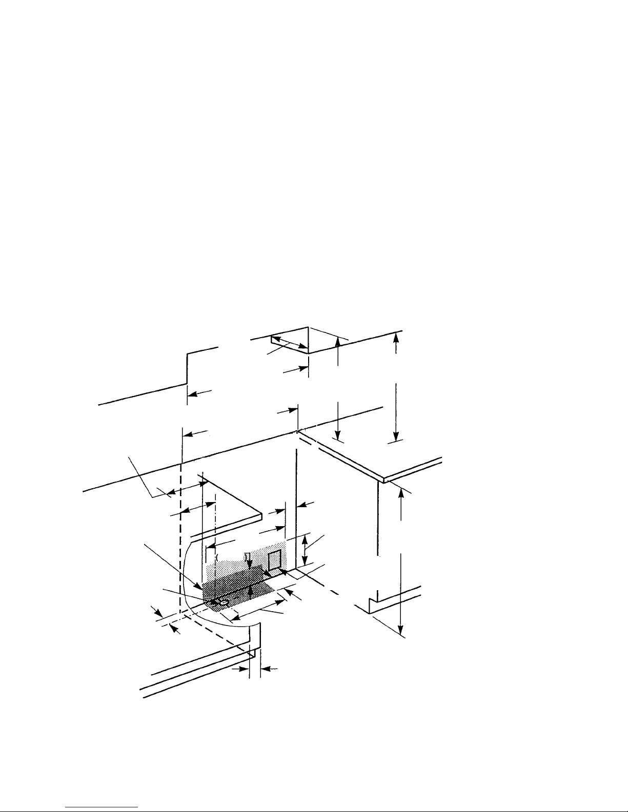
FREESTANDING GAS RANGES
Refer to Figure 2 while you read the following
installation information.
Proper installation is your responsibility. A qualified technician must install this range. Make sure
you have everything necessary for correct installation. It is the responsibility of the installer to comply
with the installation clearances specified on the
serial/rating plate. This plate is located behind the
oven door at the top of the left front frame. IMPOR-
TANT: Be sure to observe all governing codes and
ordinances.
Clearance Note:
A clearance of 30" (76.2 cm)
minimum is required when the bottom of a wood or
metal cabinet is protected by not less than
1
/4" of
flame-retardant millboard covered with not less
13" (33 cm)
max.upper
cabinet depth
"
(76.2 cm) min.
30
cabinet opening width
3
/8" (77.2 cm) min.
4" (10.2 cm) min.
clearance to side
wall or other combustible material on
both sides of the
range.
Gas line opening can
be located within this
shaded area.
This area is recommended for throughthe-cabinet gas
connection and
shutoff valve
located directly
below the
pressure regulator.
9"
(22.9 cm)
(5.1 cm)
30-
opening width
18"
(45.7 cm)
1
/2
"
2-
6.4 cm
(6.4 cm)
24"
(64 cm)
2"
7
/8" (2.2 cm) min. required between cabinet
opening and door or
hinge opening.
than #28 MSG sheet steel, 0.015
0.024
"
aluminum, or 0.020" copper. A minimum
clearance of 36
"
(91.4 cm) between the top of the
"
stainless steel,
cooking platform and the bottom of an unprotected
wood or metal cabinet is required.
The cutout shown is for a 25
with a 24
"
(61 cm) base cabinet and no backsplash.
"
(63.5 cm) countertop
The maximum depth for overhead cabinets is 13
(33 cm). For the minimum vertical clearance between the cooking surface and the overhead cabinets, see the previous “Clearance Note.” Overhead cabinets installed at either side of the range
must be a minimum of 18
"
(45.7 cm) above the
cooking surface. The minimum horizontal distance
between the overhead cabinets is 30
"
(45.7 cm) min.
18
Refer to
“Clearance
Note” above.
6"
(15.2 CM)
10"
(25.4 cm)
This area is
recommended
for 120 VAC outlet
on rear wall
1
/2
"
2-
clearance upper cabinet
to countertop
"
(91.4 cm)
36
countertop
height
The Anti-Tip bracket MUST be
installed.
The range should be located away
from strong draft areas, such as
windows, doors, and strong heating vents or fans. The range should
be located for convenient use in
the kitchen. Recessed installations
must provide complete enclosure
of the sides and rear of the range.
All openings in the wall or floor
where the range is to be installed
must be sealed.
Do not pinch the power cord between the range and the wall when
you push the range into its mounting location.
The shaded area shown in the illustration is the recommended area
for a 120-VAC outlet on the rear
wall and area for a through-thewall connection for gas pipe and
shutoff valve.
A grounded electrical outlet is
required for this range.
FIGURE 2
Dimensions For Installing The
Freestanding Gas Range
"
(76.2 cm).
"
- 3 -
Page 8

Electronic Range Controls
• Used on Gas & Electric Models.
– Slide-In: Up front glass “Capacitive Touch” switch membrane.
– Freestanding: Up front glass “Capacitive Touch” membrane.
• Unique Functions:
– Sabbath Mode: Allows the oven to be operated continuously
during the Jewish Sabbath.
– Easy Convect: Automatically converts standard cooking times
and temperatures to convection cooking times and
temperatures.
– Full Meal Convect: Ten preprogrammed cook cycles and one fa-
vorite cooking cycle.
• 2nd through 5th year parts only warranty on the control.
• Electric Models:
– KESS300B
– KESC300B
– KESC307B
– KESH307B
Freestanding
• Electric Models
(Available in late 1995):
– KERS500B
– KERC500B
– KERC507B
– KERH507B
Slide-In
• Gas Models:
– KGST300B
– KGST307B
• Gas Models:
– KGRT500B
– KGRT507B
- 4 -
Page 9
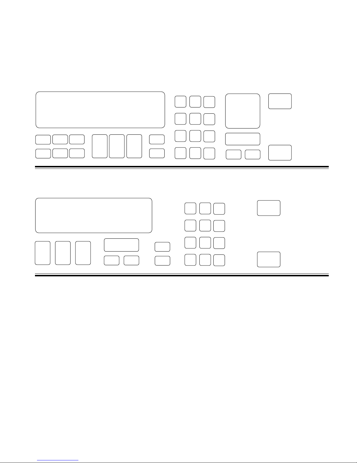
Electronic Range Controls
Keypad Layout
Convection Slide-In
Slide-In
Graphic Oven Display
23
1
4
56
78 9
Keypad Layout
Non-Convection Slide-In
Graphic Oven Display
CLOCK
12 3
SET - START
SET
START
CANCEL
10
11
10
11
#1 #2 #3
#4 #5 #6
#7 #8 #9
OVEN
#0
#12
#1 #2 #3
#4 #5 #6
#7 #8 #9
Control
LOCK
LIGHT
#0
OVEN
LIGHT
88: 88
HR MIN MIN SEC
CLOCK
SET - START
SET
START
CANCEL
START
CANCEL
OFF
START
CANCEL
OFF
Keypads:
1 = Bake
2 = Broil
3 = Clean
4 = Convection Bake
5 = Convection Broil
6 = Convection Roast
7 = Easy Convection (Baked Goods)
8 = Easy Convection (Meats)
9 = Easy Convection (Other Foods)
10 = Cook Time
11 = Stop Time
12 = Convection Full Meal
- 5 -
Page 10
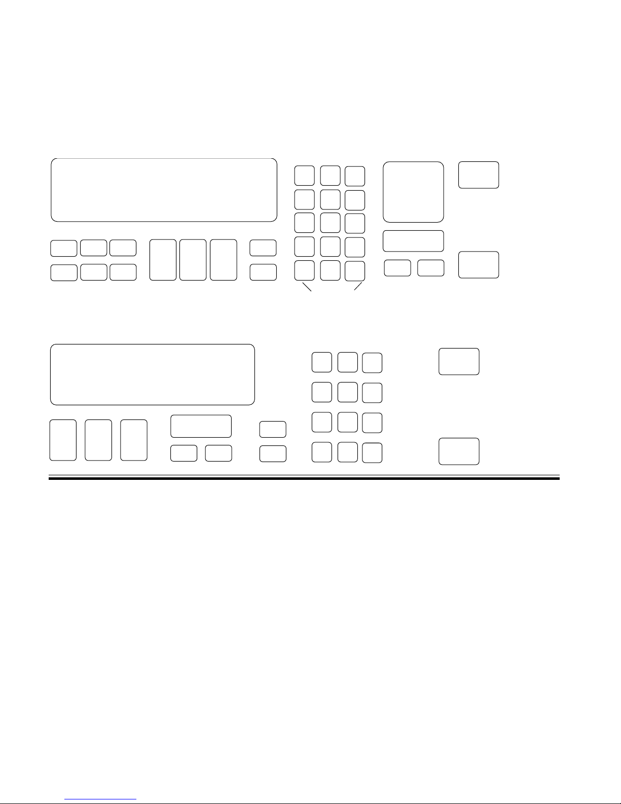
Electronic Range Controls
Keypad Layout
Convection Freestanding
Freestanding
Graphic Oven Display
23
1
78 9
56
4
Keypad Layout
Non-Convection Freestanding
Graphic Oven Display
CLOCK
SET - START
12 3
SET
START
CANCEL
10
11
10
11
#1 #2 #3
#4 #5 #6
#7 #8 #9
#0
#12
ON
NIGHT
OFF
SURFACE LIGHT
#1 #2 #3
#4 #5 #6
#7 #8 #9
SURFACE
#0
LIGHT
OVEN
LIGHT
OVEN
LIGHT
88: 88
HR MIN MIN SEC
CLOCK
SET - START
SET
START
CANCEL
START
CANCEL
OFF
START
CANCEL
OFF
Keypads:
1 = Bake
2 = Broil
3 = Clean
4 = Convection Bake
5 = Convection Broil
6 = Convection Roast
7 = Easy Convection (Baked Goods)
8 = Easy Convection (Meats)
9 = Easy Convection (Other Foods)
10 = Cook Time
11 = Stop Time
12 = Convection Full Meal
- 6 -
Page 11
Electronic Range Controls
The Graphic Display
NOTE: Ring element used on electric models only.
EASYCONVECT
NONCONVECTION MODELS
NIGHT LIGHT DELAY
SET PROBE TEMP
888
ON
RAISING
F
BREAD
DEHYDRATE CONVECTION
ENTER STANDARD COOK TIME
COOK TEMP CLEAN TIME
8:88
CHECK
FOOD AT
CLOSE CONTROL LOCK
DOOR LOCKED START ?
CONVECTION MODELS
8:88
ON
TEMP PROBE TIMED DELAY
CONTROL
DOOR LOCKED
F
START ?
88:88
HR MIN MIN SEC
CLEAN
STOP
COOK TIMER
18:88
18:88
START
TIME
STOP
TIME
- 7 -
Page 12
Electronic Range Controls
Reading The Graphic Display
Broiler Heat Indicator
NIGHT LIGHT DELAY
888
ON
EASYCONVECT
Bake Heat Indicator
Ring Element
Electric Convection Only
Meat Probe Indicator
Time Savings Bar Indicates:
% Of Time Remaining In Cook Cycle
OR
SET PROBE TEMP
RAISING
F
BREAD
DEHYDRATE CONVECTION
ENTER STANDARD COOK TIME
COOK TEMP CLEAN TIME
8:88
START
18:88
CHECK
FOOD AT
CLOSE CONTROL LOCK
DOOR LOCKED START ?
18:88
TIME
STOP
TIME
% Of Time Saved With EasyConvect
- 8 -
Page 13
Electronic Range Controls
Easy Convect™
• Available on convection models only.
• Allows the consumer to cook standard oven recipes in
the convection mode.
• Three Easy Convect cooking functions:
– Baked Goods: Converts temperature by –50˚F.
– Meats: Converts time by –20% and temperature by –25˚F.
– Other: Converts time by –10% and temperature by –25˚F.
Easy Convect (Meats)
NIGHT LIGHT DELAY
SET PROBE TEMP
RAISING
EASYCONVECT
F
BREAD
DEHYDRATE CONVECTION
ENTER STANDARD COOK TIME
ON
COOK TEMP CLEAN TIME
8:88
CONVECTION MODELS
NOTE:
Ring element used
on electric models
only.
Meats
#1 #2 #3
#4 #5 #6
#7 #8 #9
#0
#12
OVEN
LIGHT
START
18:88
START
CANCEL
18:88
OFF
CHECK
FOOD AT
CLOSE CONTROL LOCK
DOOR LOCKED START ?
TIME
STOP
TIME
Time of Day
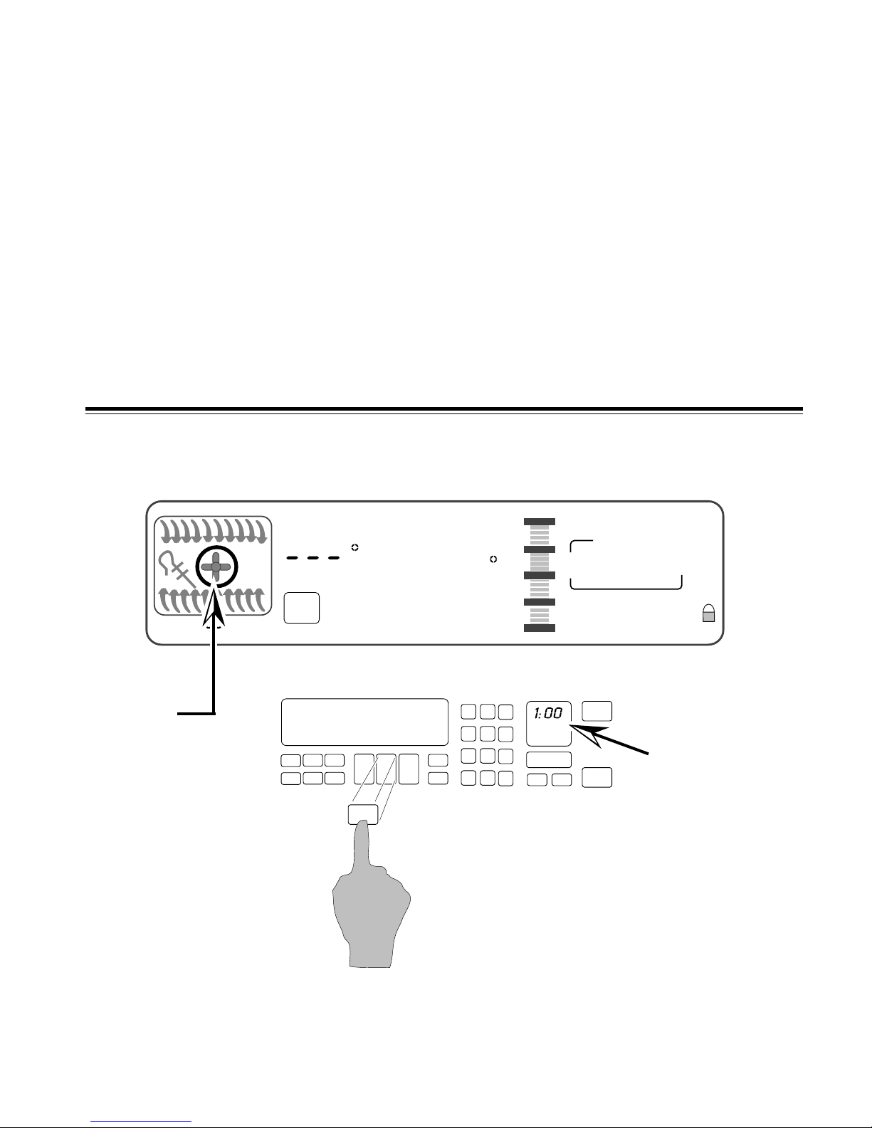
Press the “Meats” keypad.
- 9 -
Page 14
Electronic Range Controls
Easy Convect (Meats)
START
TIME
STOP
TIME
Time of Day
EASYCONVECT
NOTE:
Ring element used
on electric models
only.
NIGHT LIGHT DELAY
SET PROBE TEMP
325
ON
RAISING
F
BREAD
DEHYDRATE CONVECTION
ENTER STANDARD COOK TIME
COOK TEMP CLEAN TIME
#1 #2 #3
#4 #5 #6
#7 #8 #9
#0
#12
18:88
18:88
CHECK
FOOD AT
CLOSE CONTROL LOCK
DOOR LOCKED START ?
START
OVEN
LIGHT
CANCEL
OFF
CONVECTION MODELS
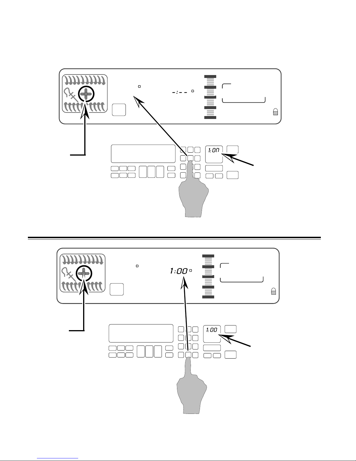
Enter the normal cooking temperature.
START
TIME
STOP
TIME
Time of Day
EASYCONVECT
NOTE:
Ring element used
on electric models
only.
NIGHT LIGHT DELAY
SET PROBE TEMP
325
ON
RAISING
F
BREAD
DEHYDRATE CONVECTION
ENTER STANDARD COOK TIME
COOK TEMP CLEAN TIME
#1 #2 #3
#4 #5 #6
#7 #8 #9
#0
#12
18:88
18:88
CHECK
FOOD AT
CLOSE CONTROL LOCK
DOOR LOCKED START ?
START
OVEN
LIGHT
CANCEL
OFF
CONVECTION MODELS
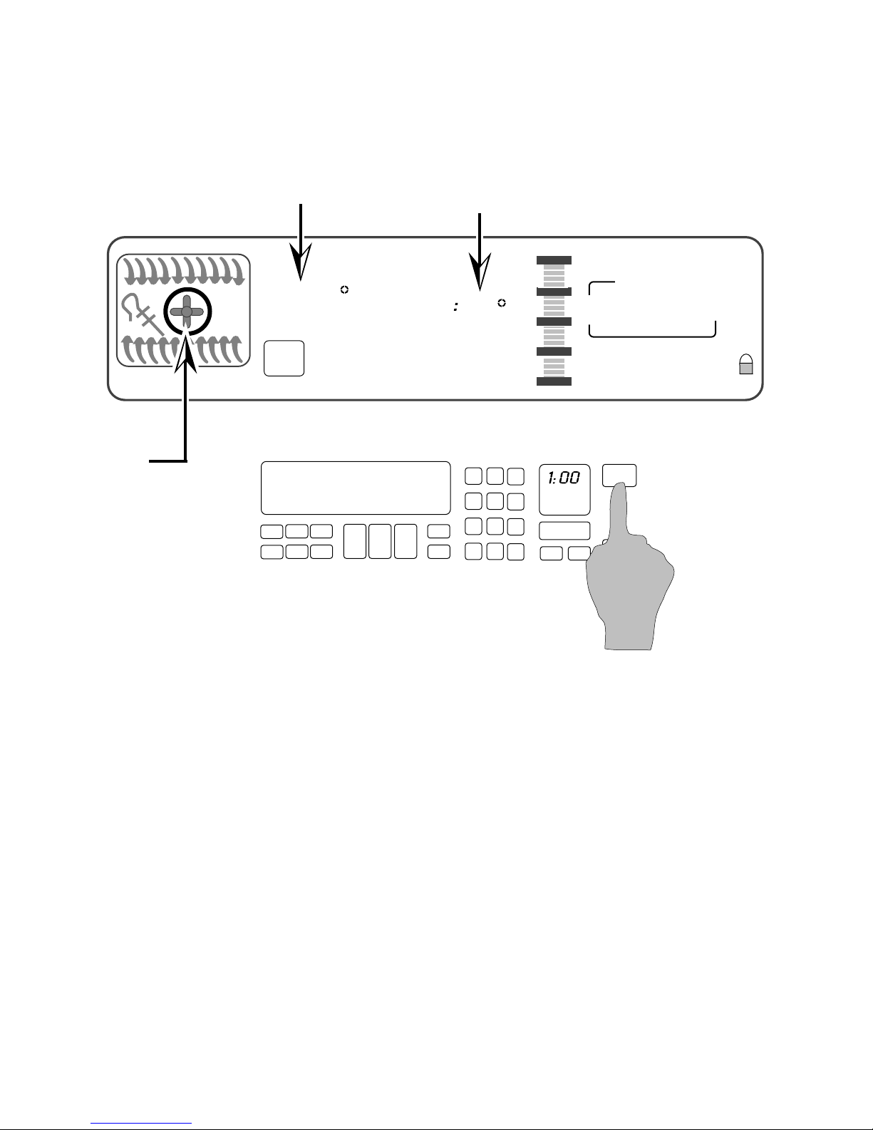
Enter the normal cooking time.
- 10 -
Page 15
Electronic Range Controls
Easy Convect (Meats)
Temperature adjusted by 25˚
NIGHT LIGHT DELAY
300
DEHYDRATE CONVECTION
ON
EASYCONVECT
NOTE:
Ring element used
on electric models
only.
ENTER STANDARD COOK TIME
COOK TEMP CLEAN TIME
F
Convection Cooking Time adjusted by 20%
SET PROBE TEMP
RAISING
BREAD
CONVECTION MODELS
48
#1 #2 #3
#4 #5 #6
#7 #8 #9
#0
#12
OVEN
LIGHT
START
1:00
CHECK
FOOD AT
CLOSE CONTROL LOCK
DOOR LOCKED START ?
START
CANCEL
1:48
OFF
TIME
STOP
TIME
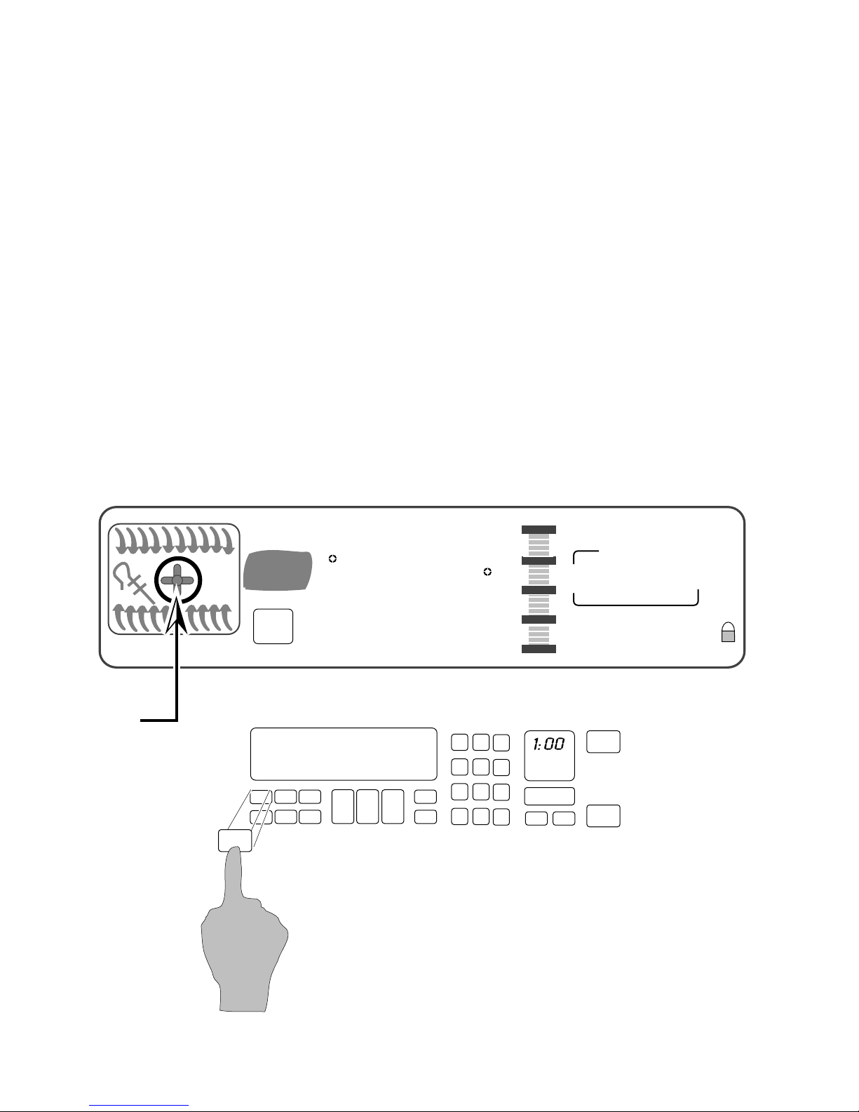
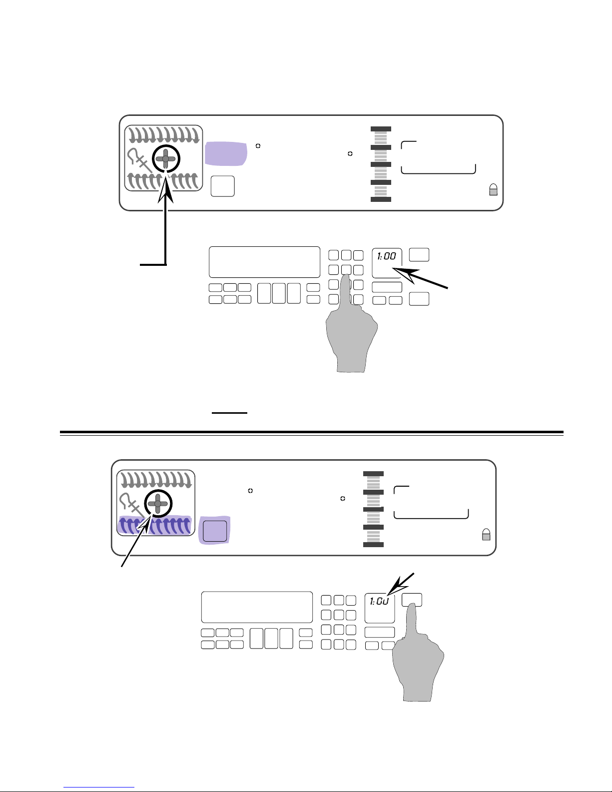
Press “Start”
After the Start button is pressed, the control
adjusts the convection cooking time by 20%
and the temperature by 25-degrees.
- 11 -
Page 16
Electronic Range Controls
Sabbath Mode
• Allows the consumer to meet the “No Work” requirements
of the Jewish Sabbath. This means that:
– The range will operate nonstop as long as power is applied to
the range bypassing the 12-hour shutdown default.
– The range will resume cooking if there is a power failure while in
this mode of operation (convection models will resume the “Favorite Cycle”).
• No tones will sound when in this mode.
• Touchpad responses are delayed by 1-second to prevent
accidentally turning the range off.
EASYCONVECT
NOTE:
Ring element used
on electric models
only.
NIGHT LIGHT DELAY
350
ON
Bake
F
DEHYDRATE CONVECTION
ENTER STANDARD COOK TIME
COOK TEMP CLEAN TIME
Use the Sabbath mode with
SET PROBE TEMP
RAISING
BREAD
8:88
#1 #2 #3
#4 #5 #6
#7 #8 #9
#12
START
18:88
START
CANCEL
OFF
18:88
CHECK
FOOD AT
CLOSE CONTROL LOCK
DOOR LOCKED START ?
OVEN
#0
LIGHT
TIME
STOP
TIME
the BAKE function only
- 12 -
Page 17
Electronic Range Controls
Sabbath Mode
START
TIME
STOP
TIME
Time of Day
EASYCONVECT
NOTE:
Ring element used
on electric models
only.
NIGHT LIGHT DELAY
SET PROBE TEMP
3 7 5
ON
RAISING
F
BREAD
DEHYDRATE CONVECTION
ENTER STANDARD COOK TIME
COOK TEMP CLEAN TIME
8:88
#12
#1 #2 #3
#4 #5 #6
#7 #8 #9
#0
18:88
18:88
CHECK
FOOD AT
CLOSE CONTROL LOCK
DOOR LOCKED START ?
START
OVEN
LIGHT
CANCEL
OFF
CONVECTION MODELS
Set the temperature you desire to use during the Sabbath
Mode. We will use
375˚.
NIGHT LIGHT DELAY
SET PROBE TEMP
3 7 5
ON
EASYCONVECT
RAISING
F
BREAD
DEHYDRATE CONVECTION
ENTER STANDARD COOK TIME
COOK TEMP CLEAN TIME
NOTE:
Ring element used
on electric models
only.
CONVECTION MODELS
Select “Start” and the oven will preheat.
8:88
#1 #2 #3
#4 #5 #6
#7 #8 #9
#12
- 13 -
START
18:88
18:88
CHECK
FOOD AT
CLOSE CONTROL LOCK
DOOR LOCKED START ?
TIME
STOP
TIME
Time of Day
START
OVEN
#0
LIGHT
CANCEL
OFF
Page 18
Electronic Range Controls
Sabbath Mode
NIGHT LIGHT DELAY
SET PROBE TEMP
3 7 5
ON
EASYCONVECT
RAISING
F
BREAD
DEHYDRATE CONVECTION
ENTER STANDARD COOK TIME
COOK TEMP CLEAN TIME
8:88
CONVECTION MODELS
NOTE:
Ring element used
on electric models
only.
#1 #2 #3
#4 #5 #6
#7 #8 #9
#0
#12
OVEN
LIGHT
START
18:88
START
CANCEL
OFF
18:88
Time of Day
CHECK
FOOD AT
CLOSE CONTROL LOCK
DOOR LOCKED START ?
TIME
STOP
TIME
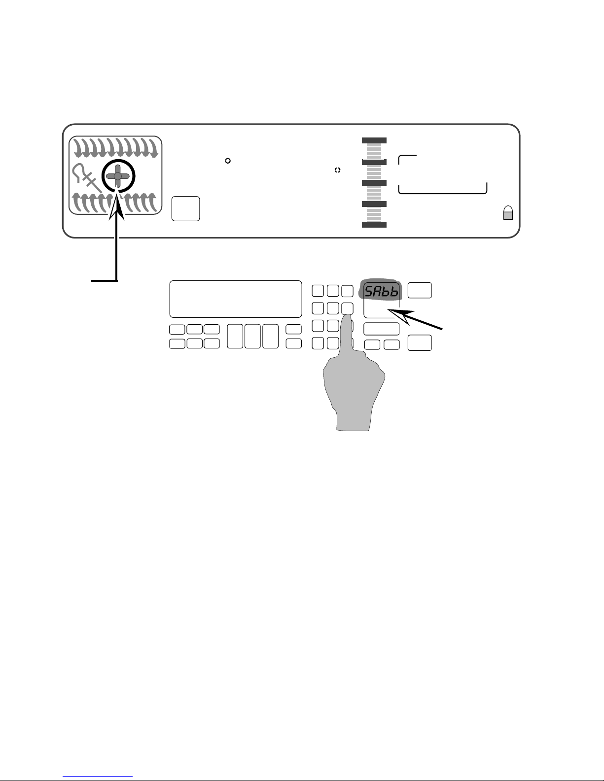
• When the oven has finished preheating, press and hold
the #6 keypad for 5-seconds.
• The Time of Day display changes to “SAbb.”
• The Sabbath Mode can only be cancelled by pressing and
holding the #6 keypad.
- 14 -
Page 19
Electronic Range Controls
Clean Mode
EASYCONVECT
NIGHT LIGHT DELAY
SET PROBE TEMP
RAISING
F
BREAD
DEHYDRATE CONVECTION
ON
ENTER STANDARD COOK TIME
COOK TEMP CLEAN TIME
Clean
3:30
#1 #2 #3
#4 #5 #6
#7 #8 #9
#12
4:30
CHECK
FOOD AT
CLOSE CONTROL LOCK
DOOR LOCKED START ?
OVEN
#0
LIGHT
CANCEL
8:00
START
OFF
START
TIME
STOP
TIME
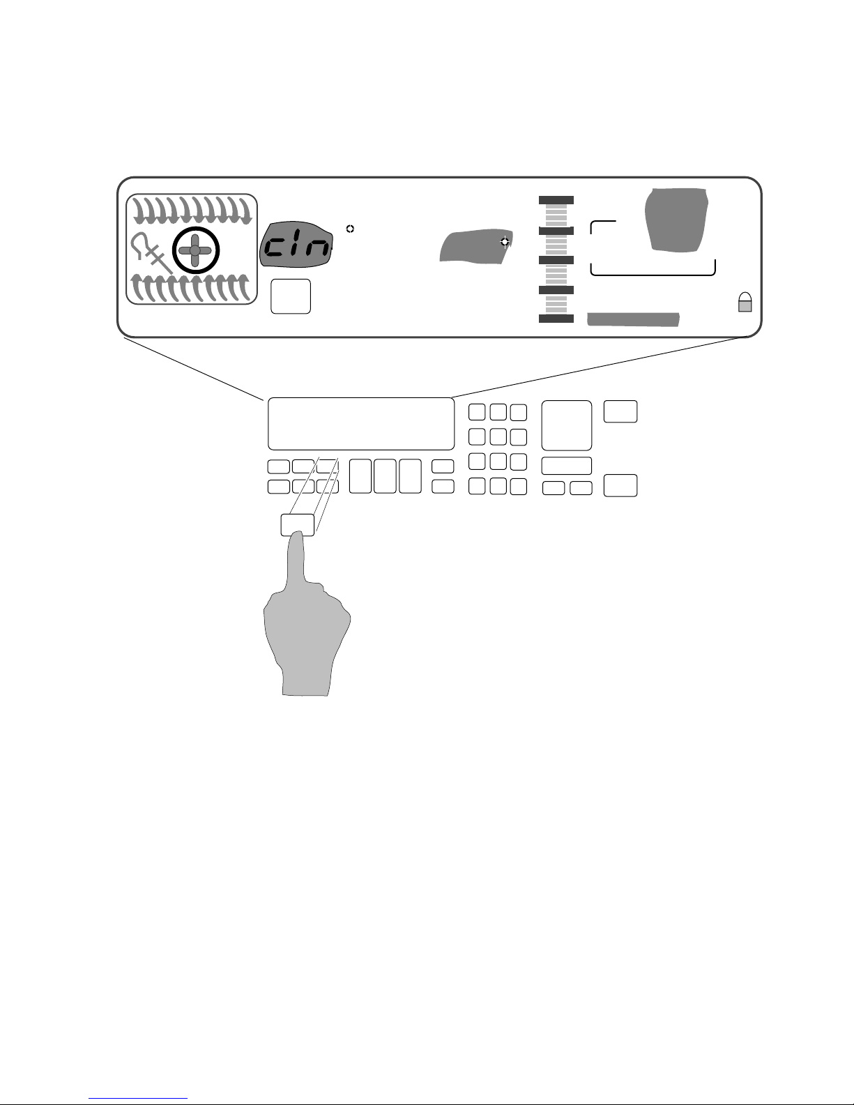
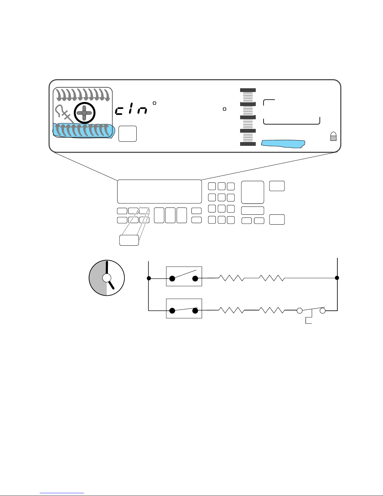
The customer selects the “Clean Mode” on the touch panel.
The 3-
1
/2 hour default clean time will be displayed (the cus-
tomer can select a clean cycle of between 2-
The Start and Stop times will be displayed (based on the time
selected by the customer).
- 15 -
1
/2 and 4-1/2 hours).
Page 20
Electronic Range Controls
Clean Mode
EASYCONVECT
12
11
10
9
8
7
6
NIGHT LIGHT DELAY
SET PROBE TEMP
RAISING
F
BREAD
DEHYDRATE CONVECTION
ON
Clean
ENTER STANDARD COOK TIME
COOK TEMP CLEAN TIME
1
2
L1
3
4
5
3:30
#1 #2 #3
#4 #5 #6
#7 #8 #9
#12
P6
#0
Ignitor
OVEN
LIGHT
Broil
4:30
CHECK
FOOD AT
CLOSE CONTROL LOCK
DOOR LOCKED START ?
CANCEL
Broil
Valve
8:00
START
OFF
START
TIME
STOP
TIME
N
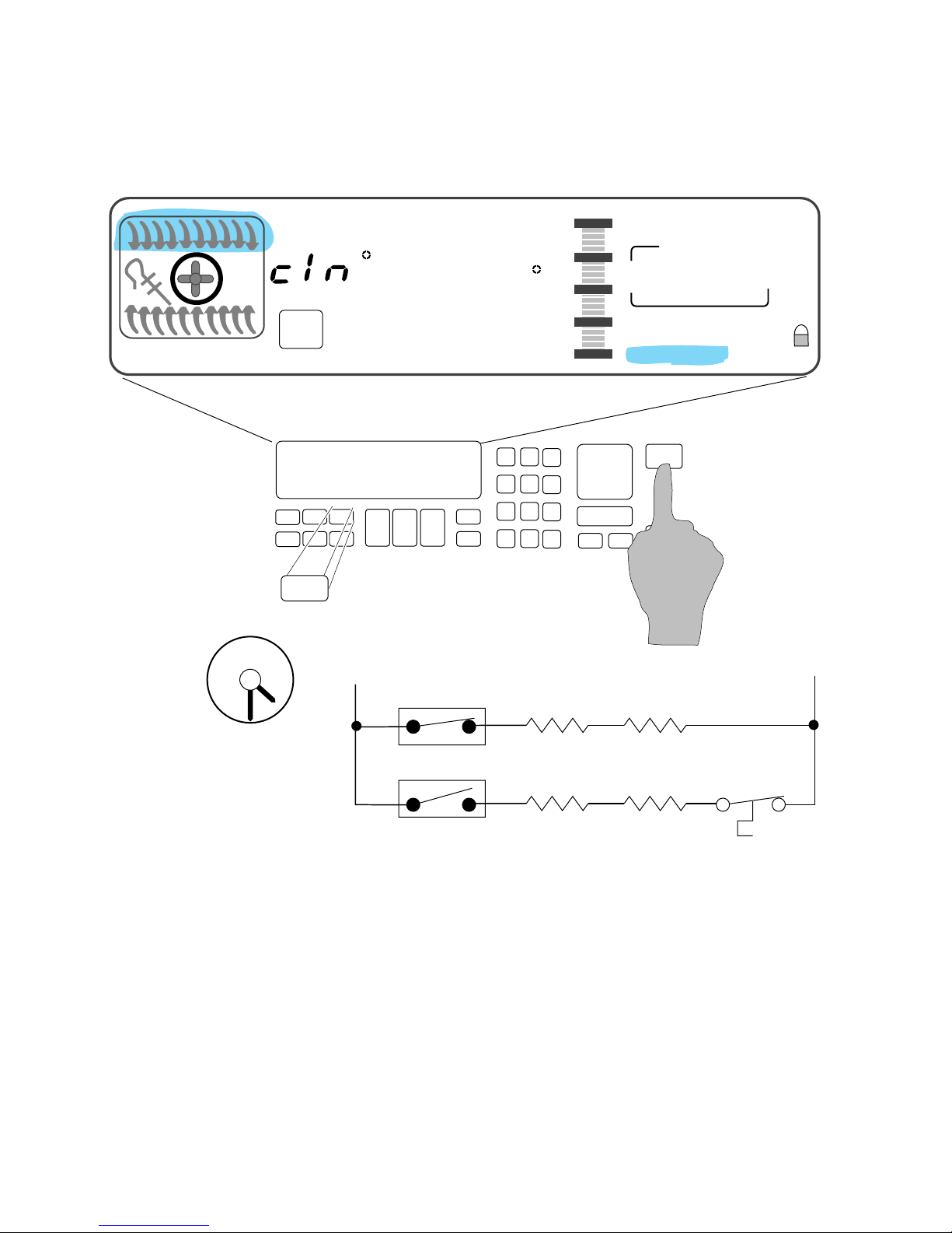
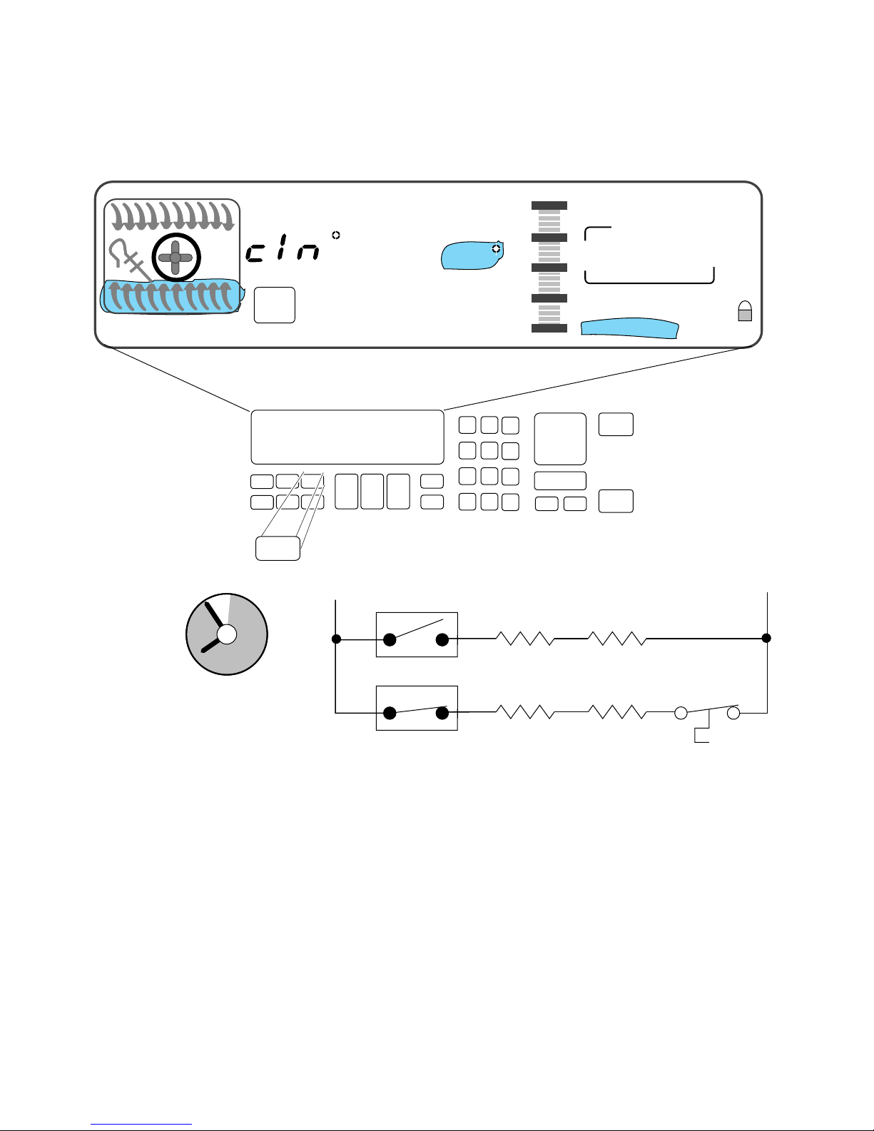
At the instant of start:
• The door will lock.
• The Broil Ignitor is ON.
• The Broil Valve is ON.
• The oven will start heating.
- 16 -
P11
Bake
Ignitor
Bake
Valve
Page 21
Electronic Range Controls
Clean Mode
EASYCONVECT
12
11
10
9
NIGHT LIGHT DELAY
SET PROBE TEMP
RAISING
F
BREAD
DEHYDRATE CONVECTION
ON
Clean
1
ENTER STANDARD COOK TIME
COOK TEMP CLEAN TIME
L1
2
3
3:00
#1 #2 #3
#4 #5 #6
#7 #8 #9
#12
P6
#0
Broil
Ignitor
OVEN
LIGHT
4:30
CHECK
FOOD AT
CLOSE CONTROL LOCK
DOOR LOCKED START ?
START
CANCEL
Broil
Valve
8:00
OFF
START
TIME
STOP
TIME
N
8
7
6
4
5
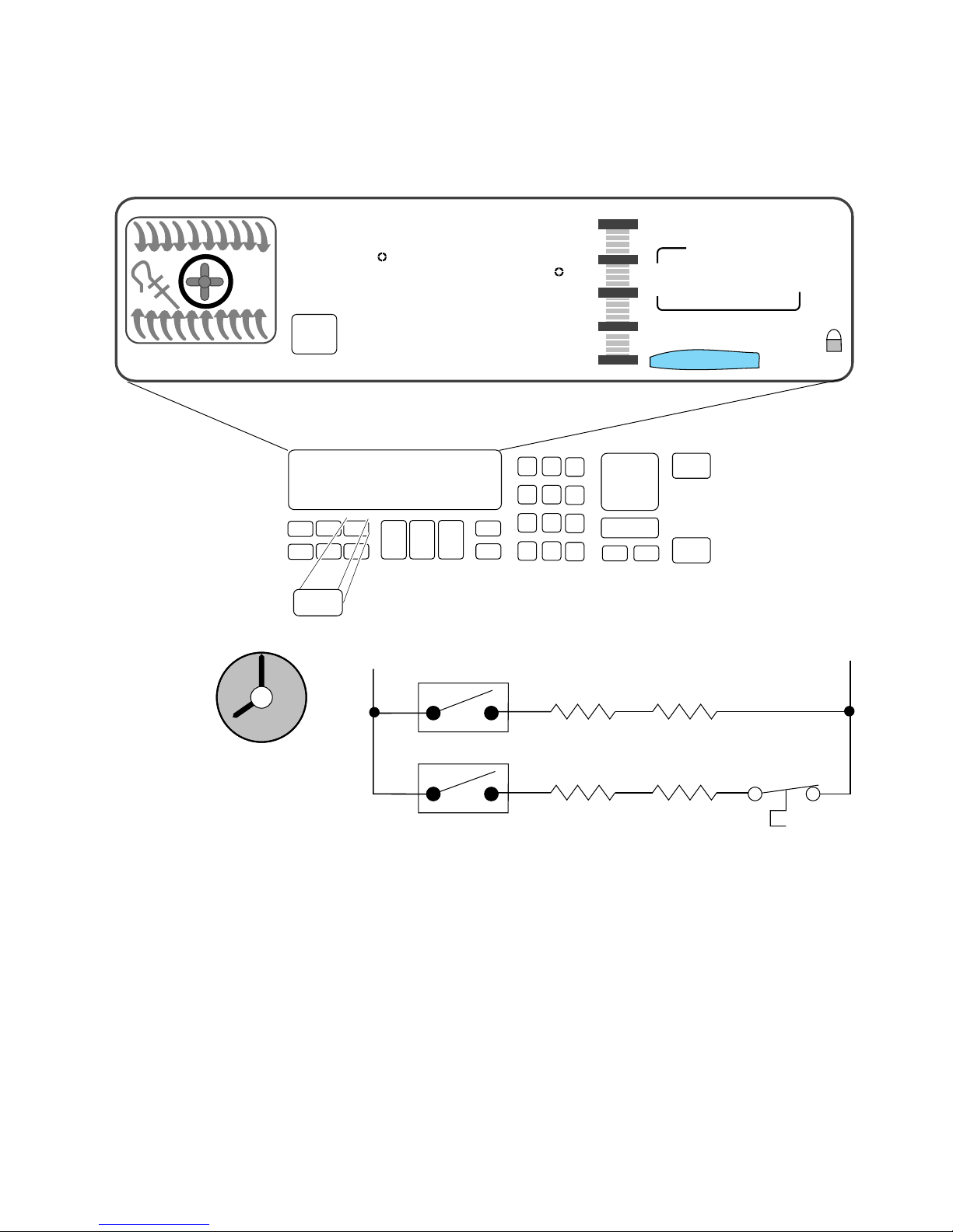
After 30-minutes:
• The Bake Ignitor is ON.
• The Bake Valve is ON.
• The Broil Circuit is OFF.
P11
Bake
Ignitor
Bake
Valve
- 17 -
Page 22
Electronic Range Controls
Clean Mode
EASYCONVECT
12
11
10
9
NIGHT LIGHT DELAY
SET PROBE TEMP
RAISING
F
BREAD
DEHYDRATE CONVECTION
ON
Clean
1
ENTER STANDARD COOK TIME
COOK TEMP CLEAN TIME
L1
2
3
:05
#1 #2 #3
#4 #5 #6
#7 #8 #9
#12
P6
#0
OVEN
LIGHT
Broil
Ignitor
4:30
CHECK
FOOD AT
CLOSE CONTROL LOCK
DOOR LOCKED START ?
CANCEL
Broil
Valve
8:00
START
OFF
START
TIME
STOP
TIME
N
8
7
6
4
5
P11
Bake
Ignitor
Bake
Valve
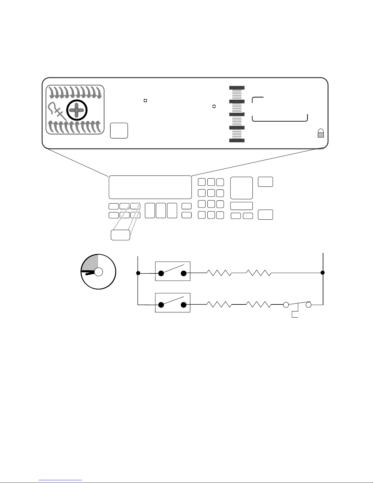
After approximately 3-hours:
• The display shows that the clean time remaining is
5-minutes.
- 18 -
Page 23
Electronic Range Controls
Clean Mode
EASYCONVECT
12
11
10
9
NIGHT LIGHT DELAY
SET PROBE TEMP
RAISING
8:88
ON
Clean
1
F
BREAD
DEHYDRATE CONVECTION
ENTER STANDARD COOK TIME
COOK TEMP CLEAN TIME
L1
2
3
8:88
#1 #2 #3
#4 #5 #6
#7 #8 #9
#12
P6
#0
OVEN
LIGHT
Broil
Ignitor
8:88
CHECK
FOOD AT
CLOSE CONTROL LOCK
DOOR LOCKED START ?
START
CANCEL
Broil
Valve
8:88
OFF
START
TIME
STOP
TIME
N
8
7
6
4
5
P11
Bake
Ignitor
Bake
Valve
When the Clean Cycle ends:
• The oven door will remain locked.
• The display will show “locked” for as long as the oven is
hot.
- 19 -
Page 24
Electronic Range Controls
Clean Mode
EASYCONVECT
12
11
10
9
NIGHT LIGHT DELAY
SET PROBE TEMP
RAISING
8:88
ON
Clean
1
F
BREAD
DEHYDRATE CONVECTION
ENTER STANDARD COOK TIME
COOK TEMP CLEAN TIME
L1
2
3
8:88
#1 #2 #3
#4 #5 #6
#7 #8 #9
#12
P6
OVEN
#0
LIGHT
Broil
Ignitor
8:88
CHECK
FOOD AT
CLOSE CONTROL LOCK
DOOR LOCKED START ?
START
CANCEL
Broil
Valve
8:88
OFF
START
TIME
STOP
TIME
N
8
7
6
4
5
P11
Bake
Ignitor
Bake
Valve
After approximately 45-minutes:
• The oven door will unlock.
• The oven door “locked” display will turn off when the
oven temperature is below 600˚F.
- 20 -
Page 25

Things To Know
• Replacement service controls must be programmed to
meet the range configuration they are being used in. Failure to do so will result in an F-code (F1 - E3).
Program Procedure
Press the following keypad sequence after the unit has been
powered up.
Convection Freestanding/Slide In:
- Convection Broil
- Clean
- Baked Goods
- Stop Time
- #1, #9, #0
- Timer Set
- Start
- Cancel
Non-Convection Freestanding/Slide In:
- Clean
- Stop Time
- #0
- Oven Light
- #1
- Start
- Cancel
This will set the board for the proper range configuration.
NOTE: These program sequences also check all the capacitive
glass touchpad keys. If the sequence does not work, unplug
the unit, wait 10-seconds, plug the unit back in, and rerun the
sequence from the “PF” mode.
- 21 -
Page 26

Things To Know (Cont’d)
• On gas models only, the conmvection fan is delay-started
1-minute for any convection cook cycle.
• On gas models the convection fan cycles on and off during operation.
— On for 10-seconds and off for 20-seconds in convection broil.
— On for 30-seconds and off for 1-seconds in convection bake/
roast.
• The convection fan stops running if the oven door is
opened.
• The temperature sensor mounting screw is removed from
the rear on freestanding models, and from the front on
slide-in models.
• The gas shut-off lever is located on the gas safety valve.
• All gas models are shipped with the LP conversions ori-
fice kit Part #9751844 packed with the Use & Care
materials. The kit consists of the following:
(2) 6" burner spuds
(2) 8" burner spuds
(1) broiler burner spud
- 22 -
Page 27
Range Cooling System
L1 N
N
L1
THERMAL
SWITCH
THERMAL
SWITCH
COOLING FAN
“OFF”
COOLING FAN
“ON”
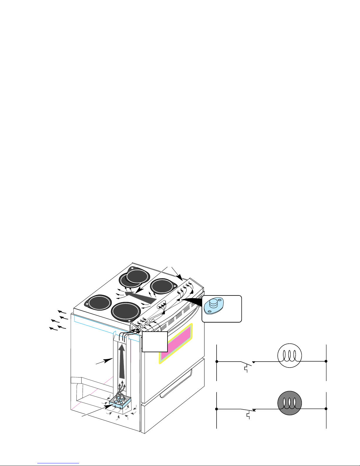
Refer to Figure 3 while you read this section.
• A cooling fan, in the storage drawer area, is used to maintain
optimum temperatures in the console areas.
• Restrictions to the air flow in the cooling systems can cause premature failure of the controls or the thermal protectors.
The cooling fan draws air from inside the base of the cabinet. It
forces the air up the air channel, which is located under the left side
panel, to the opening at the end of the control panel chassis. Air then
flows across the chassis below the control panel, and cools it. Air
enters through the series of holes in front of the range top, flows beneath it, and exits to the outside through slots in the rear panel.
The cooling fan is operated by the cooling fan thermal switch, which
is located under the right side of the control panel, on the control
panel chassis.
When the control panel temperature exceeds 104˚F, the thermal
switch will close and turn ON the cooling fan.
When the control panel chassis temperature drops below the turn-on
point, the thermal switch opens, and turns the cooling fan off.
AIR FLOWS FROM
CONTROL PANEL
UNDER RANGE TOP
AIR FLOWS OUT
REAR PANEL
COOLING
FAN THERMAL
AIR CHANNEL
SWITCH
AIR INLETS
UNDER
CONTROL
PANEL
FIGURE 3
The Cooling System
COOLING FAN
- 23 -
Page 28
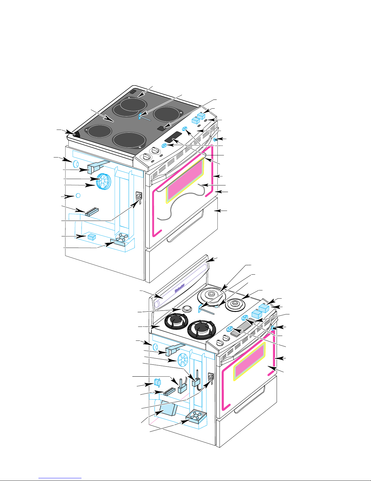
Component Layout
Refer to Figures 4 & 5 for the locations of the individual
components in the electric and gas ranges.
SURFACE ELEMENTS
OVEN TEMPERATURE SENSOR
HOT SURFACE LIGHTS (4)
OVEN VENT
OVEN LIGHT
DOOR LATCH
SOLENOID
CONVECTION FAN
CONVECTION BAKE
ELEMENT
BAKE ELEMENT
SHUTDOWN SWITCH
TERMINAL BLOCK
TEMPERATURE
PROBE SOCKET
DLB RELAY
COOLING FAN
MAINTOP GLASS
HALOGEN
FLUORESCENT
LAMP
OVEN VENT
HALOGEN
INFINITE CONTROLS (4)
INDICATOR LIGHT (4)
CONTROL PANEL
OVEN LIGHT SWITCH
CONTROL PANEL
THERMAL SWITCHES
ELECTRONICS BOARD
BROIL/CONVECTION
ELEMENTS
FIBERGLASS SEAL
BAKE ELEMENT
OVEN DOOR GLASS
STORAGE DRAWER
FIGURE 4
The Electric Range Components
BACKGUARD GLASS
10,000 BTU BURNER/
BEZEL & IGNITOR (2)
OVEN SENSOR
BAKE BURNER SHUTDOWN SWITCH
6,000 BTU BURNER/
BEZEL & IGNITOR (2)
GAS VALVE (4)
CONTROL PANEL
ELECTRONICS BOARD
MAINTOP GLASS
OVEN LIGHT
DOOR LATCH SOLENOID
CONVECTION FAN & ELEMENT
PRESSURE REGULATOR
SAFETY VALVE
BALLAST
TERMINAL BLOCK
TEMPERATURE
PROBE SOCKET
IGNITOR
MODULE
COOLING FAN
- 24 -
OVEN LIGHT SWITCH
COOLING FAN
THERMAL SWITCH
CONTROL PANEL
SHUTDOWN SWITCH
FIBERGLASS OVEN
DOOR SEAL
OVEN DOOR GLASS
FIGURE 5
The Gas Range Components
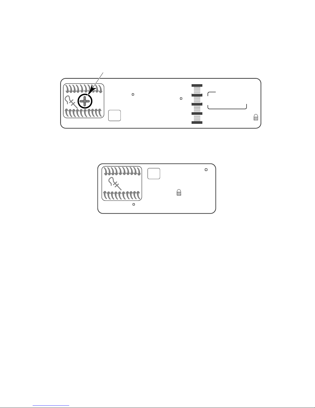
Page 29

Accessing Components Behind
The Control Panel
The following major components are serviced by removing
the control panel:
- Computer Board - Burner Valves & Switches
- Capacitive Glass Panel - Hi Limit Thermal Switch
- Cooling Fan Thermal Switch
END CAP
HALOGEN
HALOGEN
SCREW
(On Slide-In Models Only)
CONTROL PANEL
ELECTRONICS
BOARD
CONTROL PANEL
SCREWS (3)
END CAP
SCREW
(On Slide-In Models Only)
FIGURE 6
Removing The Electric Range Control Panel
Refer to Figure 6 for the following steps.
1. Unplug the power cord plug from the AC receptacle.
2. Open the oven door, and remove the three screws from under the
control panel and the two from the end caps, then close the oven
door.
3. On gas models, remove the four (4) burner valve stem nuts.
4. Lift the control panel and set it on the maintop so that you can access
the components.
- 25 -
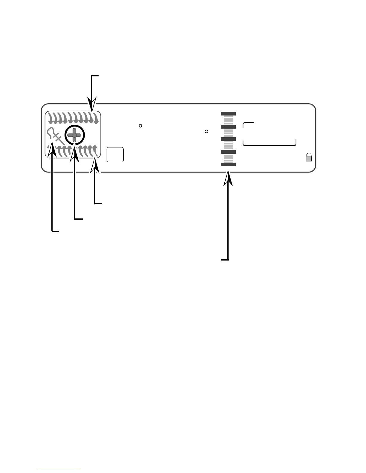
Page 30

Accessing Components Under
The Cooktop
The following major components are serviced by raising the
cooktop:
- Surface Burner Assemblies
- Ignitors
- Ceran Element Assemblies
RANGE TOP
SCREWS (4)
HALOGEN
HALOGEN
END CAP
SCREW
(On Slide-In Models Only)
Accessing Components Under The Cooktop
END CAP SCREW
(On Slide-In Models Only)
CONTROL PANEL
ELECTRONICS BOARD
CONTROL PANEL
SCREWS (3)
FIGURE 7
Refer to Figure 7 for the following steps.
1. Unplug the power cord plug from the AC receptacle, and if necessary,
move the range out from the wall.
2. Open the oven door, and remove the three screws from under the
control panel, and the two from the end caps, then close the oven
door.
3. Set the control panel on the maintop, and remove the four chassis
screws (two on each side) that are under the control panel, then
position the control panel back in its normal location.
4. Lift the front of the maintop and prop it up so you can easily access
the components underneath. Be careful not to stress any of the
wiring when you lift the top.
- 26 -
Page 31

Accessing Components Behind
The Rear Panel
The following major components are serviced by removing
the component and access covers:
- Locking Solenoid
- Convection Fan Motor
- Temperature Sensor (Freestanding Models Only)
REAR
PANEL
TABS
PANEL
MOUNTING
SCREWS (3)
COMPONENTS
COVER
TAB
Accessing Components Behind
The Rear Panel
ACCESS
COVER
FIGURE 8
Refer to Figure 8 for the following steps.
1. Disconnect the power cord plug from the AC receptacle.
2. Pull the range out from the wall or cabinet cutout far enough to
access the back panel.
3. Remove the three screws from the component and access covers
that are mounted to the rear panel, then unhook and remove the
covers.
- 27 -
Page 32

Accessing Components Behind
The Storage Drawer
The following major components are serviced by removing
the storage drawer:
- Cooling Fan
- Burner Valve & Pressure Regulator
- Ignitor Module
- Double Line Break (DLB) Relay (Electric Only)
HALOGEN
HALOGEN
PRESSURE
REGULATOR
FAN RELAY
COOLING FAN
HOUSING
FIGURE 9
Removing The Storage Drawer
Electric Models
STORAGE DRAWER
IGNITOR
MODULE
COOLING FAN
STORAGE DRAWER
HOUSING
FIGURE 10
Removing The Storage Drawer
Gas Models
Refer to Figures 9 or 10 for the following steps.
1. Unplug the range’s power cord plug from the AC receptacle.
2. Remove the storage drawer from the range.
3. From inside the storage area, remove the three mounting screws
from the housing.
4. Remove the housing by sliding it forward and unhooking the tab from
the slot in the bottom of the range.
- 28 -
Page 33

Error Codes
The microcomputer contains self-diagnostic codes that will be displayed on the control panel whenever a failure occurs when using the
range. Audible 1-second and 5-second tones will sound to alert the user
whenever a failure code is being displayed. Each code can be cancelled
by pressing the CANCEL/OFF keypad. The code will return if the user
attempts to use the range before the failure has been corrected.
The F/E-Codes will be displayed for the indicated reasons, shown in the
following chart.
FAULT ERROR
F1 E0 N/A FAULT EEPROM
F1 E1 N/A
F1 E3 7
F1 E4 2 Q8 SHORTED Q8 SHORTED SUSPECT CONTROL
F1 E9 0 STACK OVERFLOW STACK OVERFLOW, HIGHEST PRIORITY SUSPECT CONTROL
F2 E0 4
F2 E2 3
F2 E3 5 KEY DOWN TOO LONG KEY HELD DOWN TOO LONG OR KEYBOARD SHORT
F2 E4 6 KEYS UNSETTLED KEYS UNSETTLED PROBABLY DUE TO NOISE
F3 E0 9 OPEN PLAT PLAT SENSOR OPEN
F3 E1 8 SHORTED PLAT PLAT SENSOR SHORTED
F3 E2 10 OVEN TEMP TOO HIGH OVEN TEMP TOO HIGH (RUNAWAY)
F4 E1 15
F5 E1 13
F5 E3 1
F5 E5 14
F5 E6 16
F5 E7 17
FAULT
PRIORITY
FAULT CONSTANT
NAME IN SOFTWARE
EEPROM CHECKSUM
ERROR
CONFIG JUMPERS NO
MATCH
CANCEL KEY TOO
LOW
CANCEL KEY
CHANNEL
SHORTED MEAT
PROBE
SELF-CLEAN LATCH
WILL NOT MAKE
LOSS OF GND L1 N
REVERSE
SELF CLEAN TEMP
NOT SATISFIED
DOOR OPEN AND
LOCKED
DOOR WILL NOT
UNLATCH
FAULT
DESCRIPTION
EEPROM READ FAULT (SILENT FAULT, NOT
DISPLAYED)
EEPROM CHECKSUM DOES NOT MATCH AT START
KEY (SILENT FAULT, NOT DISPLAYED)
CONFIGURATION JUMPER CHANGE, FREESTAND,
ELECTRIC SWITCHES ,OR P9 (PIN 6 TO 7) CHANGED
SINCE POWER UP
CANCEL KEY LEVEL TOO LOW (OPEN)
CANCEL KEY LOOP TEST FAILED
HEAT PROBE SHORTED (LESS THAN 1500 OHMS)
SELF-CLEAN LATCH WILL NOT MAKE AFTER
30-SECONDS
LOSS OF 120 VAC ACROSS L1 TO GROUND, OR Q19
CIRCUIT ERROR
SELF-CLEAN TEMPERATURE NOT SATISFIED AFTER
30-MINUTES
DOOR LOCKED WITH DOOR OPEN
DOOR UNLOCKED AND WILL NOT UNLATCH
SERVICE
ACTION
SUSPECT CONTROL
SUSPECT CONTROL
SUSPECT CONTROL
SUSPECT KEYPAD
ASSEMBLY
SUSPECT KEYPAD
ASSEMBLY
SUSPECT KEYPAD
ASSEMBLY
SUSPECT KEYPAD
ASSEMBLY
SUSPECT KEYPAD
ASSEMBLY
SUSPECT TEMP
SENSOR
SUSPECT TEMP
SENSOR
SUSPECT TEMP
SENSOR
SUSPECT MEAT
PROBE
SUSPECT INPUT
SWITCH
SUSPECT INPUT
SWITCH
SUSPECT INPUT
SWITCH
SUSPECT INPUT
SWITCH
F6 E0 12 AMBIENT OVER TEMP AMBIENT SENSOR OPENED (TOO HOT) F6
F7 E0 11 INPUT SWITCH ERROR
PF
INPUT SWITCHES WILL NOT FOLLOW THEIR STROBE
LEVEL (SHORTED TO GROUND)
POWER FAILURE (NOT A FAILURE OF CONTROL.
PRESS CANCEL)
- 29 -
F7
Page 34

Hidden Functions
The displays shown in the chart are codes that are programmed into the
range that are not normally displayed. To use these hidden codes, touch and
hold the indicated keypad for 5-seconds. The display’s code is described in
the following chart.
KEYPAD DESCRIPTION OF CODE
Bake Calibration allows preset bake tempera-
ture to be varied +35˚F (21˚C) to –35˚F
(–21˚C).
Broil Toggles between F (Fahrenheit) &
C (Celsius).
0 Displays the last F/E code that was used
& the latest ROM revision.
1 Shows the type of range the control is
configured for.
3 Locks out the keypads so they cannot be
used.
6 Switches the range to the “Sabbath” mode.
7 Changes the frequency of the tones.
Clock Turns off the clock (time-of-day) display.
Cook Time Turns off the “end-of-cycle” tones.
Stop Time Turns off the keypad entry tones.
Timer Start Turns off the timer operating tones.
Timer Cancel Turns on the “sell” mode.
Conv. Bake Used to dehydrate food.
Baked Goods Used for raising bread dough.
- 30 -
Page 35

The Component Test Charts
L1
L2
H2
H1
P
Test Chart 1
COMPONENT
ILLUSTRATION
L1 L2
P
H1
CONTROL PANEL
SHUTDOWN SWITCH
COOLING FAN
THERMAL SWITCH
COMPONENT TEST PROCEDURE TEST RESULTS
Electronics Board
Test all input and output
connections to board.
Refer to the error codes
on the previous two
pages.
Infinite Switches
Set the ohmmeter to
R x 1.
Connect the meter leads
to the switch terminals,
and measure the conti-
Switch ON Switch OFF
L1-P = 0 Ω L1-P = ∞ Ω
L1-H1 = 0 Ω L1-H1 = ∞ Ω
L2-H2 = 0 Ω L2-H2 = ∞ Ω
nuity when the switch is
turned ON and OFF.
H2
Cooling Fan Thermostat
&
Set the ohmmeter to
R x 1.
Connect the meter leads
Above 104˚F = 0 Ω.
to the thermostat terminals, and measure the
Below 104˚F = ∞ Ω.
continuity when the
switch is heated above
104˚F, and then cools to
below 104˚F.
BAKE ELEMENT
SHUTDOWN SWITCH
Bake & Broil Element
Shutdown Switch
OR
Bake Burner Shutdown
Switch
TERMINALS
Door Latch Solenoid Set the ohmmeter to
SOLENOID
TERMINALS
Set the ohmmeter to
R x 1.
Connect the meter leads
to the thermostat terminals, and measure the
continuity when the
switch is heated above
395˚F, and then cools to
below 395˚F.
R x 10.
Connect one of the
meter leads to circuit
board pin J1-1.
Connect the other meter
lead to circuit board pin
J1-8.
- 31 -
Above 395˚F = 0 Ω.
Below 395˚F = ∞ Ω.
55 Ω. ±10 Ω
Page 36

Test Chart 2
COMPONENT
ILLUSTRATION
SENSOR TERMINALS
ELEMENT
TERMINALS
COMPONENT TEST PROCEDURE TEST RESULTS
Coil Elements Set the ohmmeter to
R x 1.
Ceran Elements
Connect the meter leads
to the element terminals, and measure the
continuity.
Set the ohmmeter to
R x 1.
Connect the meter leads
to the element terminals,
and measure the continuity. NOTE: Halogen
tubes should show continuity.
8" Coil (2600W) =
22 Ω ±5 Ω
6" Coil (1500W) =
38 Ω ±5 Ω
9" Rad (2400W) =
22 Ω ±5 Ω
7" Rad (1700W) =
32 Ω ±5 Ω
6" Rad (1400W) =
39 Ω ±5 Ω
7" Hal (1800W) = 0 Ω
Dual Oval (2500W Tot)
Hal Inner (1500W) = 0 Ω
Rad Outer (1000W) =
50 ±5 Ω
TERMINAL
COOLING
FAN MOTOR
TERMINALS
TERMINAL
CONVECTION
FAN MOTOR
Convection Fan Motor Set the ohmmeter to
R x 1.
Connect one of the
meter leads to circuit
board pin J1-1.
Connect the other meter
lead to circuit board pin
J1-6.
Cooling Fan Motor Set the ohmmeter to
R x 10.
Connect one of the
meter leads to circuit
board pin J1-1.
Connect the other meter
lead to the yellow wire
marked “FAN” on the
cooling fan thermal
switch.
15 Ω. ±3 Ω
65 Ω. ±10 Ω
- 32 -
Page 37

Test Chart 3
RED
RED
WHITE
YELLOW
COM
NO
12
3
4
COMPONENT
ILLUSTRATION
DOUBLE LINE
BREAK RELAY
OVEN TEMPERATURE
SENSOR
COMPONENT TEST PROCEDURE TEST RESULTS
Double Line Break
(DLB) Relay
Set the ohmmeter to
R x 1.
Connect the meter leads
to DLB relay terminals
3 & 4.
Apply 120 VAC to terminals 1 & 2 of the DLB
relay.
Oven Temperature
Sensor
Measure the continuity
at pins 3 & 4 with and
without AC power
applied.
Set the ohmmeter to
R x 100.
Connect one of the
meter leads to circuit
board pin P1-10.
Connect the other meter
lead to circuit board pin
P1-11.
120 VAC Applied = 0 Ω.
120 VAC Not Applied =
∞ Ω .
Temp (˚F) Resist (Ω)
32 ± 1.9 1000 ± 4.0
75 ± 2.5 1091 ± 5.3
250 ± 4.4 1453 ± 8.9
350 ± 5.4 1654 ± 10.8
450 ± 6.9 1853 ± 13.5
550 ± 8.2 2047 ± 15.8
650 ± 8.6 2237 ± 18.5
800 ± 13.6 2667 ± 24.4
CONTROL PANEL
Capacitive Glass Touch
Panel.
BAKE
ELEMENT
INNER
OUTER
ELEMENT
ELEMENT
Broil Element. Broil:
Unplug the unit, wait 10seconds, plug the unit
back in, and run the program sequence on page
23 of this Job Aid.
Set the ohmmeter to R x 1.
Connect the meter leads
to the element terminals
and measure the resistance.
- 33 -
All keypads touched,
should show a response.
Bake = 20 ± 5Ω.Bake Element.
Inner = 35 ± 5Ω.
Outer = 55 ± 5Ω.
Page 38

Wiring Diagram
Electric Ranges
L1
RETURNS
STROBES
LINK=MEMBRANE KEYS
OPEN=CAPACITANCE
GLASS KEYS
STROBES
RETURNS
L1
P L1 L2
H1 H2
R.F.
CONTROL PANEL
SHUTDOWN SW. (N.C.)
(NON RESET)
P9
J1
1
1
2
2
3
3
4
4
5
5
6
6
7
7
8
8
9
9
10
10
11
12
P4
13
P5
14
ELECTRONIC
OVEN
HARNESS
JUMPER
P1-1
2
3
4
5
6
7
8
9
10
11
P6
P2
P7
P11
CONTROL
P L1 L2
H1 H2
G
(GREEN)
NO PIN
P L1 L2
H1 H2
R.R.
L1
(BLACK)
BIDIRECTIONAL
LATCH SOLENOID
OPEN = SLIDE-IN (NO SURF. LAMP)
L.R.
COOLING FAN
THERMAL SW.
(N.O.)
DLB RELAY
CONVECT. RING (OPTIONAL)
OPEN =
DOOR
SHUT
OVEN TEMP SENSOR
N
240 V
CONVECT. FAN
MOTOR
COOLING FAN
MOTOR
BAKE ELEMENT
SHUTDOWN SW
(NON-RESET)
OUTER BROIL
INNER BROIL
BAKE
1654 Ω @ 350˚F
1000 Ω @ 32˚F
120 V120 V
P L1 L2
P L1 L2
H1 H2
H1 H2
L.R.
L.R.
OVEN
LIGHT
LATCH
OPEN =
UNLATCH
MEAT PROBE
50 kΩ @ 25˚C
SWITCH & ELEMENT
WIRING FOR COIL
ELEMENT COOKTOP
N
(WHITE)
L2
(RED)
L2
L1
ELEMENT LIGHT
5
N
2
AUXILIARY
MAIN
R.R. DUAL ELEMENT
CERAMIC COOKTOP
L1
L.F., L.R., R.F. ELEMENT
CERAMIC COOKTOP
L2
4
3
P L1 L2
H1 H2
L.R.
L1
L2
INDICATOR
HOT SURFACE
- 34 -
Page 39

BAKE (& PREHEAT)
L1 L2
ELECTRONICS
BOARD
P4
Strip Circuits
Electric Ranges
P11
BAKE
DLB
RELAY
BAKE ELEMENT
SHUTDOWN
SWITCH
P5
ECONOMY BROIL
L1
P4
STANDARD BROIL
L1
ELECTRONICS
BOARD
P6
P7
OUTER
BROIL
INNER
BROIL
DLB
RELAY
L2
BAKE ELEMENT
SHUTDOWN
SWITCH
L2
ELECTRONICS
BOARD
P4
P4
P7
P6
INNER
BROIL
OUTER
BROIL
- 35 -
DLB
RELAY
BAKE ELEMENT
SHUTDOWN
SWITCH
Page 40

CLEAN
L1
ELECTRONICS
BOARD
P4
P4
LATCH DRIVING CIRCUIT
L1
LOCK NC
J1-3
COM
UNLOCK NO
DIRECTION
RELAY
P11
P6
BAKE
OUTER
BROIL
ELECTRONICS
BOARD
270 Ω
BAKE ELEMENT
DLB
RELAY
PULSE RELAY
0.1 SECONDS
ACTIVATION
SHUTDOWN
SWITCH
LATCHING
SOLENOID
J1-8
L2
N
CONVECTION ROAST, PREHEAT
FOR CONVECTION BAKE, DEHYDRATE, & RAISING BREAD
L1
ELECTRONICS
BOARD
P4
P4
J1-3 J1-6
P11
P6
CONVECTION FAN
BAKE
OUTER
BROIL
M
MOTOR
DLB
RELAY
L2
BAKE ELEMENT
SHUTDOWN
SWITCH
N
- 36 -
Page 41

CONVECTION BROIL
L1
ELECTRONICS
BOARD
P4
P4
J1-3 J1-6
CONVECTION BAKE, DEHYDRATE, RAISING BREAD
L1
ELECTRONICS
BOARD
P4
P7
P6
P7
INNER
BROIL
OUTER
BROIL
M
COOLING FAN
MOTOR
CONV.
ELEMENT
RELAY
DLB
RELAY
BAKE ELEMENT
DLB
BAKE ELEMENT
SHUTDOWN
SWITCH
N
SHUTDOWN
SWITCH
L2
L2
OVEN LIGHT
L1
J1-6J1-3
COOLING FAN
MOTOR
ELECTRONICS
BOARD
M
OVEN LIGHT
J1-5J1-3
N
N
- 37 -
Page 42

Wiring Diagram
Gas Ranges
RETURNS
STROBES
LINK=MEMBRANE KEYS
OPEN=CAPACITANCE
GLASS KEYS
STROBES
RETURNS
NEUTRAL
120 VAC
EARTH GND
CONTROL PANEL
SHUTDOWN SW. (N.C.)
(NON RESET)
P9
1
2
3
4
5
6
7
8
9
10
11
12
13
14
J1
1
2
3
4
5
6
7
8
9
10
P4
P5
N
L
G
1 L.R.
2 L.F.
3 R.F.
4 R.R.
G
(GREEN)L1(BLACK)
SPARK
IGNITION
MODULE
1 2 3 4
COOLING FAN
THERMAL SW.
(N.O.)
FL. LAMP
N
(WHITE)
BALLAST
OVEN LIGHT
CONVECT. FAN MOTOR
COOLING FAN MOTOR
ELECTRONIC
OVEN
CONTROL
P6
P2
P7
HARNESS
JUMPER
P11
P1-1
2
3
4
5
6
7
8
9
10
11
NO PIN
- 38 -
DOOR LATCH SOLENOID
IGNITER
IGNITER
OPEN = SLIDE-IN (NO SURF. LAMP)
BAKE VALVE
BROIL VALVE
BAKE BURNER
SHUTDOWN SWITCH
(NON RESET)
OPEN =
DOOR
SHUT
OVEN TEMP SENSOR
1654 Ω @ 350˚F
1000 Ω @ 32˚F
LATCH
OPEN =
UNLATCH
MEAT PROBE
50 kΩ @ 25˚C/77˚F
Page 43

Strip Circuits
Gas Ranges
BAKE
L1 L2
ELECTRONICS
BOARD
P4
P11
BAKE
DLB
RELAY
P5
BROIL
L1
ELECTRONICS
BOARD
P4
P5
P6
CONVECTION BAKE & ROAST
L1
ELECTRONICS
BOARD
P4
P11
P6
IGNITOR
IGNITOR
BROIL
BAKE
OUTER
BROIL
BROIL
VALVE
BAKE
VALVE
N
N
BAKE BURNER
SHUTDOWN
SWITCH
P5
J1-6
CONVECT. FAN
MOTOR
- 39 -
Page 44

CONVECTION BROIL
L1
ELECTRONICS
BOARD
P4
P6
BROIL
IGNITOR
N
BROIL
VALVE
P5
CLEAN
First 30-Minutes
L1
ELECTRONICS
After 30-Minutes
L1
ELECTRONICS
BOARD
BOARD
J1-6
P6
P11
BROIL
IGNITOR
BAKE
IGNITOR
CONVECT. FAN
MOTOR
BROIL
VALVE
BAKE
VALVE
N
N
BAKE BURNER
SHUTDOWN SWITCH
- 40 -
Page 45

LATCH DRIVING CIRCUIT
L1
LOCK NC
J1-3
COM
UNLOCK NO
DIRECTION
RELAY
COOLING FAN MOTOR
L1
COOLING FAN
THERMAL SWITCH
COM
N.C.
ELECTRONICS
BOARD
270 Ω
COOLING FAN
PULSE RELAY
0.1 SECONDS
ACTIVATION
MOTOR
J1-8
N
LATCHING
SOLENOID
N
OVEN LIGHT
L1
ELECTRONICS
BOARD
P4
P5
N
OVEN LIGHT
J1-5
- 41 -
Page 46

Confirmation of Understanding
1. On gas model ranges, the convection fan cycles ON for - seconds
and OFF for
2. The oven temperature sensor mounting screw is accessed from the
on freestanding models, and from the on slide-in
models.
3. All Gas model ranges are shipped with LP conversion orifice kits:
True False.
4. Replacement service controls DO NOT have to be programmed to meet
the range configuration they are being used in, otherwise an F-code will
occur:
True False.
5. A cooling fan is used to maintain optimum temperatures in the console
area of gas ranges only:
- seconds in convection broil mode.
True False.
6. A
freestanding and slide-in ranges.
7. Restricting the
ture failure of the controls and thermal switches.
8. To set the control for Celsius temperature, press and hold the #6 keypad
for 5-seconds:
9. An error code of F5 - E3 means that the range is connected to a nonpolarized receptacle:
10. The cooling fan motor can be replaced from the console area:
True False.
speed fan, located in the storage drawer area, is used on
in the cooking systems can cause prema-
True False.
True False.
- 42 -
Page 47

— NOTES —
- 43 -
Page 48

1. 10-seconds & 20-seconds
2. rear & front
3. True
4. False
5. False
6. single
7. air flow
8. False
9. True
10. False
Answers
- 44 -
Page 49

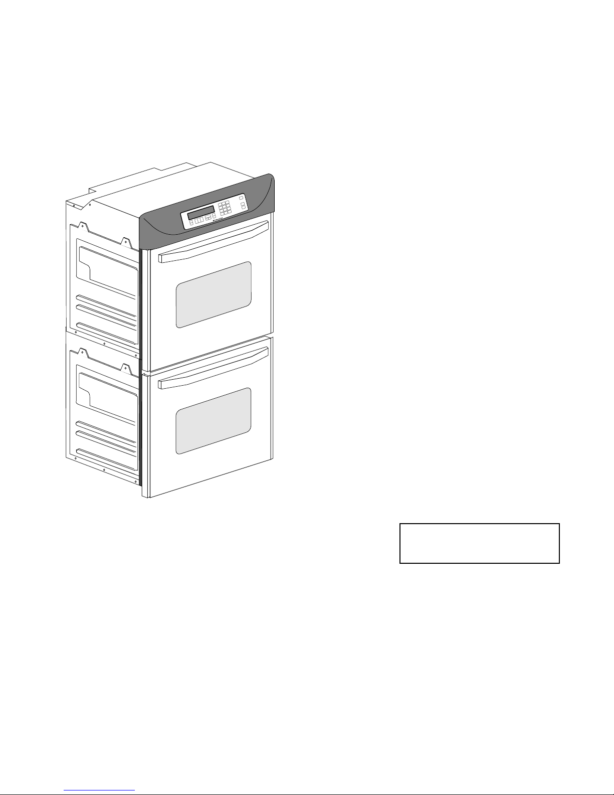
KitchenAid Electronic Range Controls
“B” Line Freestanding/Slide-In
“D” Line Built-In Wall Ovens
• Developed by Digital Appliance Control (DAC).
• Used on Gas & Electric Models.
– Slide-In: Up front glass “Capacitive Touch” switch membrane.
– Freestanding: Up front glass “Capacitive Touch” membrane.
– Wall Ovens: Mylar touch membrane switch.
• Unique Functions:
– Sabbath Mode: Allows the oven to be operated continuously
during the Jewish Sabbath.
– Eacy Convect: Automatically converts standard cooking times
and temperatures to convection cooking times and
temperatures.
– Full Meal Convect: Ten preprogrammed cook cycles and one fa-
vorite cooking cycle.
• 2nd through 5th year parts only warranty.
- 1 -
Page 50

KitchenAid Electronic Range Controls
“B” Line Slide-In
• Electric Models:
– KESS300B
– KESC300B
– KESC307B
– KESH307B
• Gas Models:
– KGST300B
– KGST307B
- 2 -
Page 51

KitchenAid Electronic Range Controls
“B” Line Slide-In
Keypad Layout
Convection Slide-In
Graphic Oven Display
23
1
4
56
78 9
Keypad Layout
Non-Convection Slide-In
Graphic Oven Display
CLOCK
12 3
SET - START
SET
START
CANCEL
10
11
10
11
#1 #2 #3
#4 #5 #6
#7 #8 #9
OVEN
#0
#12
#1 #2 #3
#4 #5 #6
#7 #8 #9
Control
LOCK
LIGHT
#0
OVEN
LIGHT
88: 88
HR MIN MIN SEC
CLOCK
SET - START
SET
START
CANCEL
START
CANCEL
OFF
START
CANCEL
OFF
Keypads:
1 = Bake
2 = Broil
3 = Clean
4 = Convection Bake
5 = Convection Broil
6 = Convection Roast
7 = Easy Convection (Baked Goods)
8 = Easy Convection (Meats)
9 = Easy Convection (Other Foods)
10 = Cook Time
11 = Stop Time
12 = Convection Full Meal
- 3 -
Page 52

KitchenAid Electronic Range Controls
“B” Line Freestanding
• Electric Models (Available in late 1995):
– KERS500B
– KERC500B
– KERC507B
– KERH507B
• Gas Models:
– KGRT500B
– KGRT507B
- 4 -
Page 53

KitchenAid Electronic Range Controls
“B” Line Freestanding
Keypad Layout
Convection Freestanding
Graphic Oven Display
23
1
78 9
56
4
Keypad Layout
Non-Convection Freestanding
Graphic Oven Display
CLOCK
SET - START
12 3
SET
START
CANCEL
10
11
10
11
#1 #2 #3
#4 #5 #6
#7 #8 #9
#0
#12
ON
NIGHT
OFF
SURFACE LIGHT
#1 #2 #3
#4 #5 #6
#7 #8 #9
SURFACE
#0
LIGHT
OVEN
LIGHT
OVEN
LIGHT
88: 88
HR MIN MIN SEC
CLOCK
SET - START
SET
START
CANCEL
START
CANCEL
OFF
START
CANCEL
OFF
Keypads:
1 = Bake
2 = Broil
3 = Clean
4 = Convection Bake
5 = Convection Broil
6 = Convection Roast
7 = Easy Convection (Baked Goods)
8 = Easy Convection (Meats)
9 = Easy Convection (Other Foods)
10 = Cook Time
11 = Stop Time
12 = Convection Full Meal
- 5 -
Page 54

KitchenAid Electronic Range Controls
“B” Line Freestanding/Slide-In
NOTE:
Ring element used on
electric models only.
EASYCONVECT
8:88
F
NIGHT LIGHT DELAY
SET PROBE TEMP
888
ON
RAISING
F
BREAD
DEHYDRATE CONVECTION
ENTER STANDARD COOK TIME
COOK TEMP CLEAN TIME
8:88
CHECK
FOOD AT
CLOSE CONTROL LOCK
DOOR LOCKED START ?
CONVECTION MODELS
ON
TEMP PROBE TIMED DELAY
CONTROL
DOOR LOCKED
START ?
88:88
HR MIN MIN SEC
CLEAN
STOP
COOK TIMER
NONCONVECTION MODELS
18:88
18:88
START
TIME
STOP
TIME
- 6 -
Page 55

KitchenAid Electronic Range Controls
“D” Line Wall Ovens
• Electric Models:
24" Ovens 27" Ovens 30" Ovens
KEBI141D KEBI171D KEBI101D
KEBS147D KEBS177D KEBS107D
KEBS246D KEBS276D KEBS206D
KEBS247D KEBS277D KEBS207D
KEBS278D KEBS208D
- 7 -
Page 56

KitchenAid Electronic Range Controls
“D” Line Wall Ovens
Keypad Layout
Convection Single
Graphic Oven Display
23
1
4
56
78 9
Keypad Layout
Non-Convection Single
Graphic Oven Display
CLOCK
12 3
SET - START
SET
START
CANCEL
10
11
10
11
#1 #2 #3
#4 #5 #6
#7 #8 #9
OVEN
#0
#12
#1 #2 #3
#4 #5 #6
#7 #8 #9
Control
LOCK
LIGHT
#0
OVEN
LIGHT
88: 88
HR MIN MIN SEC
CLOCK
SET - START
SET
CANCEL
START
START
CANCEL
OFF
START
CANCEL
OFF
Keypads:
1 = Bake
2 = Broil
3 = Clean
4 = Convection Bake
5 = Convection Broil
6 = Convection Roast
7 = Easy Convection (Baked Goods)
8 = Easy Convection (Meats)
9 = Easy Convection (Other Foods)
10 = Cook Time
11 = Stop Time
12 = Convection Full Meal
- 8 -
Page 57

KitchenAid Electronic Range Controls
“D” Line Wall Ovens
Keypad Layout
Convection Double
Graphic Oven Display
UPPER
OVEN
LOWER
OVEN
23
1
7
5
46
Keypad Layout
Non-Convection Double
Graphic Oven Display
UPPER
OVEN
LOWER
OVEN
123
CLOCK
SET - START
SET
START
89
CANCEL
10
11
10
11
#1 #2 #3
#4 #5 #6
#7 #8 #9
#12
LIGHT
OVEN
#0
#1 #2 #3
#4 #5 #6
#7 #8 #9
Control
#0
LOCK
OVEN
LIGHT
88: 88
HR MIN MIN SEC
CLOCK
SET - START
SET
CANCEL
START
START
UPPER OVEN
CANCEL / OFF
LOWER OVEN
CANCEL / OFF
START
UPPER OVEN
CANCEL / OFF
LOWER OVEN
CANCEL / OFF
Keypads:
1 = Bake
2 = Broil
3 = Clean
4 = Convection Bake
5 = Convection Broil
6 = Convection Roast
7 = Easy Convection (Baked Goods)
8 = Easy Convection (Meats)
9 = Easy Convection (Other Foods)
10 = Cook Time
11 = Stop Time
12 = Convection Full Meal
- 9 -
Page 58

KitchenAid Electronic Range Controls
“D” Line Wall Ovens
DELAY
SET PROBE TEMP
RAISING
888
ON
EASYCONVECT
F
BREAD
DEHYDRATE CONVECTION
ENTER STANDARD COOK TIME
COOK TEMP CLEAN TIME
8:88
CONVECTION SINGLE
8:88
ON
TEMP PROBE TIMED DELAY
CONTROL
DOOR LOCKED
F
START ?
88:88
HR MIN MIN SEC
CLEAN
STOP
COOK TIMER
NON-CONVECTION SINGLE
START
18:88
CHECK
FOOD AT
CLOSE CONTROL LOCK
DOOR LOCKED START ?
18:88
TIME
STOP
TIME
- 10 -
Page 59

KitchenAid Electronic Range Controls
“D” Line Wall Ovens
DELAY
SET PROBE TEMP
RAISING
888
ON
EASYCONVECT
F
BREAD
DEHYDRATE CONVECTION
ENTER STANDARD COOK TIME
COOK TEMP CLEAN TIME
8:88
CONVECTION DOUBLE
NON-CONVECTION DOUBLE
START
18:88
18:88
CHECK
FOOD AT
CLOSE CONTROL LOCK
DOOR LOCKED START ?
TIME
STOP
TIME
EASYCONVECT
DELAY
888
ON
F
CLOSE
DOOR
LOCKED
- 11 -
Page 60

Reading The Graphic Display
Broiler Heat Indicator
NIGHT LIGHT DELAY
888
ON
EASYCONVECT
Bake Heat Indicator
Ring Element
Electric Convection Only
Meat Probe Indicator
Time Savings Bar Indicates:
% Of Time Remaining In Cook Cycle
OR
% Of Time Saved With EasyConvect
SET PROBE TEMP
RAISING
F
BREAD
DEHYDRATE CONVECTION
ENTER STANDARD COOK TIME
COOK TEMP CLEAN TIME
8:88
START
18:88
CHECK
FOOD AT
CLOSE CONTROL LOCK
DOOR LOCKED START ?
18:88
TIME
STOP
TIME
- 12 -
Page 61

KitchenAid Electronic Range Controls
“Easy Convect”
• Available on convection models only.
• Allows the consumer to cook standard oven recipes
in the convection mode.
• Three Easy Convect cooking functions:
– Baked Goods: Converts time by –50% and temperature by –50˚F.
– Meats: Converts time by –20% and temperature by –25˚F.
– Other: Converts time by –10% and temperature by –25˚F.
• Let’s review the operation of the Easy Convect cycle.
We will use the “Meats” cycle to show how it works.
- 13 -
Page 62

KitchenAid Electronic Range Controls
“Easy Convect (Meats)”
NIGHT LIGHT DELAY
SET PROBE TEMP
RAISING
EASYCONVECT
ON
F
BREAD
DEHYDRATE CONVECTION
ENTER STANDARD COOK TIME
COOK TEMP CLEAN TIME
8:88
CONVECTION MODELS
NOTE:
Ring element used
on electric models
only.
Meats
#1 #2 #3
#4 #5 #6
#7 #8 #9
#0
#12
OVEN
LIGHT
START
18:88
START
CANCEL
OFF
18:88
Time of Day
CHECK
FOOD AT
CLOSE CONTROL LOCK
DOOR LOCKED START ?
TIME
STOP
TIME
Press the “Meats” keypad.
- 14 -
Page 63

KitchenAid Electronic Range Controls
“Easy Convect (Meats)”
Temperature
EASYCONVECT
NIGHT LIGHT DELAY
SET PROBE TEMP
RAISING
F
BREAD
DEHYDRATE CONVECTION
ON
ENTER STANDARD COOK TIME
COOK TEMP CLEAN TIME
8:88
CHECK
FOOD AT
CLOSE CONTROL LOCK
DOOR LOCKED START ?
18:88
18:88
CONVECTION MODELS
NOTE:
Ring element used
on electric models
only.
#1 #2 #3
#4 #5 #6
#7 #8 #9
#0
#12
OVEN
LIGHT
START
CANCEL
OFF
Time of Day
Enter the normal cooking temperature.
START
TIME
STOP
TIME
- 15 -
Page 64

KitchenAid Electronic Range Controls
“Easy Convect (Meats)”
NIGHT LIGHT DELAY
SET PROBE TEMP
3
ON
EASYCONVECT
NOTE:
Ring element used
on electric models
only.
RAISING
F
BREAD
DEHYDRATE CONVECTION
ENTER STANDARD COOK TIME
COOK TEMP CLEAN TIME
CONVECTION MODELS
8:88
#1 #2 #3
#4 #5 #6
#7 #8 #9
#12
START
18:88
START
CANCEL
OFF
18:88
Time of Day
CHECK
FOOD AT
CLOSE CONTROL LOCK
DOOR LOCKED START ?
OVEN
#0
LIGHT
TIME
STOP
TIME
Enter the normal cooking temperature.
- 16 -
Page 65

KitchenAid Electronic Range Controls
“Easy Convect (Meats)”
NIGHT LIGHT DELAY
SET PROBE TEMP
32
ON
EASYCONVECT
NOTE:
Ring element used
on electric models
only.
RAISING
F
BREAD
DEHYDRATE CONVECTION
ENTER STANDARD COOK TIME
COOK TEMP CLEAN TIME
CONVECTION MODELS
8:88
#1 #2 #3
#4 #5 #6
#7 #8 #9
#12
START
18:88
START
CANCEL
OFF
18:88
Time of Day
CHECK
FOOD AT
CLOSE CONTROL LOCK
DOOR LOCKED START ?
OVEN
#0
LIGHT
TIME
STOP
TIME
Enter the normal cooking temperature.
- 17 -
Page 66

KitchenAid Electronic Range Controls
“Easy Convect (Meats)”
NIGHT LIGHT DELAY
SET PROBE TEMP
325
ON
EASYCONVECT
NOTE:
Ring element used
on electric models
only.
RAISING
F
BREAD
DEHYDRATE CONVECTION
ENTER STANDARD COOK TIME
COOK TEMP CLEAN TIME
CONVECTION MODELS
#1 #2 #3
#4 #5 #6
#7 #8 #9
#0
#12
OVEN
LIGHT
START
18:88
START
CANCEL
18:88
Time of Day
OFF
CHECK
FOOD AT
CLOSE CONTROL LOCK
DOOR LOCKED START ?
TIME
STOP
TIME
Enter the normal cooking temperature.
- 18 -
Page 67

KitchenAid Electronic Range Controls
“Easy Convect (Meats)”
NIGHT LIGHT DELAY
SET PROBE TEMP
RAISING
F
BREAD
EASYCONVECT
NOTE:
Ring element used
on electric models
only.
325
ON
DEHYDRATE CONVECTION
ENTER STANDARD COOK TIME
COOK TEMP CLEAN TIME
CONVECTION MODELS
#1 #2 #3
#4 #5 #6
#7 #8 #9
#0
#12
OVEN
LIGHT
START
18:88
START
CANCEL
18:88
Time of Day
OFF
CHECK
FOOD AT
CLOSE CONTROL LOCK
DOOR LOCKED START ?
TIME
STOP
TIME
Enter the normal cooking time.
- 19 -
Page 68

KitchenAid Electronic Range Controls
“Easy Convect (Meats)”
NIGHT LIGHT DELAY
SET PROBE TEMP
325
ON
EASYCONVECT
NOTE:
Ring element used
on electric models
only.
RAISING
F
BREAD
DEHYDRATE CONVECTION
ENTER STANDARD COOK TIME
COOK TEMP CLEAN TIME
CONVECTION MODELS
#1 #2 #3
#4 #5 #6
#7 #8 #9
#0
#12
OVEN
LIGHT
START
18:88
START
CANCEL
OFF
18:88
Time of Day
CHECK
FOOD AT
CLOSE CONTROL LOCK
DOOR LOCKED START ?
TIME
STOP
TIME
Enter the normal cooking time.
- 20 -
Page 69

KitchenAid Electronic Range Controls
“Easy Convect (Meats)”
NIGHT LIGHT DELAY
SET PROBE TEMP
325
ON
EASYCONVECT
NOTE:
Ring element used
on electric models
only.
RAISING
F
BREAD
DEHYDRATE CONVECTION
ENTER STANDARD COOK TIME
COOK TEMP CLEAN TIME
CONVECTION MODELS
#1 #2 #3
#4 #5 #6
#7 #8 #9
#0
#12
OVEN
LIGHT
START
18:88
START
CANCEL
OFF
18:88
Time of Day
CHECK
FOOD AT
CLOSE CONTROL LOCK
DOOR LOCKED START ?
TIME
STOP
TIME
Enter the normal cooking time.
- 21 -
Page 70

KitchenAid Electronic Range Controls
“Easy Convect (Meats)”
Temperature adjusted by 25˚
NIGHT LIGHT DELAY
300
DEHYDRATE CONVECTION
ON
EASYCONVECT
NOTE:
Ring element used
on electric models
only.
ENTER STANDARD COOK TIME
COOK TEMP CLEAN TIME
F
Convection Cooking Time adjusted by 20%
SET PROBE TEMP
RAISING
BREAD
CONVECTION MODELS
48
#1 #2 #3
#4 #5 #6
#7 #8 #9
#0
#12
OVEN
LIGHT
START
1:00
CHECK
FOOD AT
CLOSE CONTROL LOCK
DOOR LOCKED START ?
START
CANCEL
1:48
OFF
TIME
STOP
TIME
Press “Start”
After the Start button is pressed, the control
adjusts the convection cooking time by 20%
and the temperature by 25-degrees.
- 22 -
Page 71

KitchenAid Electronic Range Controls
“Sabbath Mode”
• Available on all KitchenAid models.
• Allows the consumer to meet the “No Work” require-
ments of the Jewish Sabbath. This means that:
– The range will operate nonstop as long as power is applied to
the range.
– The range will resume cooking if there is a power failure while in
this mode of operation (convection models will resume the “Favorite Cycle”).
• No tones will sound when in this mode.
• Touchpad responses are delayed by 1-second to pre-
vent accidentally turning the range off.
• Let’s review the operation of the Sabbath Mode.
- 23 -
Page 72

KitchenAid Electronic Range Controls
“Sabbath Mode”
EASYCONVECT
NOTE:
Ring element used
on electric models
only.
NIGHT LIGHT DELAY
8:88
ON
Bake
F
DEHYDRATE CONVECTION
ENTER STANDARD COOK TIME
COOK TEMP CLEAN TIME
SET PROBE TEMP
RAISING
BREAD
8:88
#1 #2 #3
#4 #5 #6
#7 #8 #9
#12
START
18:88
START
CANCEL
OFF
18:88
CHECK
FOOD AT
CLOSE CONTROL LOCK
DOOR LOCKED START ?
OVEN
#0
LIGHT
TIME
STOP
TIME
- 24 -
Page 73

KitchenAid Electronic Range Controls
“Sabbath Mode”
Temperature
NIGHT LIGHT DELAY
SET PROBE TEMP
3:50
ON
EASYCONVECT
RAISING
F
BREAD
DEHYDRATE CONVECTION
ENTER STANDARD COOK TIME
COOK TEMP CLEAN TIME
8:88
CONVECTION MODELS
NOTE:
Ring element used
on electric models
only.
#1 #2 #3
#4 #5 #6
#7 #8 #9
#0
#12
OVEN
LIGHT
Set the temperature you desire to use during
the Sabbath Mode. We will use
START
18:88
START
CANCEL
OFF
18:88
Time of Day
CHECK
FOOD AT
CLOSE CONTROL LOCK
DOOR LOCKED START ?
TIME
STOP
TIME
375˚.
- 25 -
Page 74

KitchenAid Electronic Range Controls
“Sabbath Mode”
NIGHT LIGHT DELAY
SET PROBE TEMP
- - 3
ON
EASYCONVECT
RAISING
F
BREAD
DEHYDRATE CONVECTION
ENTER STANDARD COOK TIME
COOK TEMP CLEAN TIME
8:88
CLOSE CONTROL LOCK
DOOR LOCKED START ?
CONVECTION MODELS
NOTE:
Ring element used
on electric models
only.
#1 #2 #3
#4 #5 #6
#7 #8 #9
#0
#12
OVEN
LIGHT
18:88
START
CANCEL
OFF
18:88
CHECK
FOOD AT
START
TIME
STOP
TIME
Time of Day
Set the temperature you desire to use during
the Sabbath Mode. We will use
375˚.
- 26 -
Page 75

KitchenAid Electronic Range Controls
“Sabbath Mode”
NIGHT LIGHT DELAY
SET PROBE TEMP
- 3 7
ON
EASYCONVECT
RAISING
F
BREAD
DEHYDRATE CONVECTION
ENTER STANDARD COOK TIME
COOK TEMP CLEAN TIME
8:88
CLOSE CONTROL LOCK
DOOR LOCKED START ?
CONVECTION MODELS
NOTE:
Ring element used
on electric models
only.
#1 #2 #3
#4 #5 #6
#7 #8 #9
#0
#12
OVEN
LIGHT
18:88
START
CANCEL
OFF
18:88
CHECK
FOOD AT
START
TIME
STOP
TIME
Time of Day
Set the temperature you desire to use during
the Sabbath Mode. We will use
- 27 -
375˚.
Page 76

KitchenAid Electronic Range Controls
“Sabbath Mode”
NIGHT LIGHT DELAY
SET PROBE TEMP
3 7 5
ON
EASYCONVECT
RAISING
F
BREAD
DEHYDRATE CONVECTION
ENTER STANDARD COOK TIME
COOK TEMP CLEAN TIME
8:88
CLOSE CONTROL LOCK
DOOR LOCKED START ?
CONVECTION MODELS
NOTE:
Ring element used
on electric models
only.
#1 #2 #3
#4 #5 #6
#7 #8 #9
#0
#12
OVEN
LIGHT
18:88
START
CANCEL
18:88
OFF
CHECK
FOOD AT
START
TIME
STOP
TIME
Time of Day
Set the temperature you desire to use during
the Sabbath Mode. We will use
375˚.
- 28 -
Page 77

KitchenAid Electronic Range Controls
“Sabbath Mode”
NIGHT LIGHT DELAY
SET PROBE TEMP
3 7 5
ON
EASYCONVECT
RAISING
F
BREAD
DEHYDRATE CONVECTION
ENTER STANDARD COOK TIME
COOK TEMP CLEAN TIME
8:88
CONVECTION MODELS
NOTE:
Ring element used
on electric models
only.
#1 #2 #3
#4 #5 #6
#7 #8 #9
#0
#12
OVEN
LIGHT
START
18:88
CHECK
FOOD AT
CLOSE CONTROL LOCK
DOOR LOCKED START ?
18:88
Time of Day
START
CANCEL
OFF
TIME
STOP
TIME
Select “Start” and the oven will preheat.
- 29 -
Page 78

KitchenAid Electronic Range Controls
“Sabbath Mode”
NIGHT LIGHT DELAY
SET PROBE TEMP
3 7 5
ON
EASYCONVECT
RAISING
F
BREAD
DEHYDRATE CONVECTION
ENTER STANDARD COOK TIME
COOK TEMP CLEAN TIME
8:88
CONVECTION MODELS
NOTE:
Ring element used
on electric models
only.
#1 #2 #3
#4 #5 #6
#7 #8 #9
#0
#12
OVEN
LIGHT
START
18:88
START
CANCEL
OFF
18:88
Time of Day
CHECK
FOOD AT
CLOSE CONTROL LOCK
DOOR LOCKED START ?
TIME
STOP
TIME
When the oven has finished preheating, press and
hold the #6 keypad for 5-seconds.
- 30 -
Page 79

KitchenAid Electronic Range Controls
“Sabbath Mode”
NIGHT LIGHT DELAY
SET PROBE TEMP
3 7 5
ON
EASYCONVECT
RAISING
F
BREAD
DEHYDRATE CONVECTION
ENTER STANDARD COOK TIME
COOK TEMP CLEAN TIME
8:88
CONVECTION MODELS
NOTE:
Ring element used
on electric models
only.
#1 #2 #3
#4 #5 #6
#7 #8 #9
#0
#12
OVEN
LIGHT
START
18:88
START
CANCEL
OFF
18:88
Time of Day
CHECK
FOOD AT
CLOSE CONTROL LOCK
DOOR LOCKED START ?
TIME
STOP
TIME
The Time of Day display changes to “SAbb.”
- 31 -
Page 80

KitchenAid Electronic Range Controls
“Sabbath Mode”
NIGHT LIGHT DELAY
SET PROBE TEMP
3 7 5
ON
EASYCONVECT
RAISING
F
BREAD
DEHYDRATE CONVECTION
ENTER STANDARD COOK TIME
COOK TEMP CLEAN TIME
8:88
CLOSE CONTROL LOCK
DOOR LOCKED START ?
CONVECTION MODELS
NOTE:
Ring element used
on electric models
only.
#1 #2 #3
#4 #5 #6
#7 #8 #9
#0
#12
OVEN
LIGHT
18:88
START
CANCEL
18:88
OFF
CHECK
FOOD AT
START
TIME
STOP
TIME
Time of Day
The Sabbath Mode can only be cancelled
by pressing and holding the #6 keypad.
- 32 -
Page 81

KitchenAid Electronic Range Controls
“Clean Mode”
START
CANCEL
OFF
START
TIME
STOP
TIME
EASYCONVECT
NIGHT LIGHT DELAY
SET PROBE TEMP
8:88
ON
RAISING
F
BREAD
DEHYDRATE CONVECTION
ENTER STANDARD COOK TIME
COOK TEMP CLEAN TIME
8:88
#1 #2 #3
#4 #5 #6
#7 #8 #9
#0
#12
18:88
CHECK
FOOD AT
CLOSE CONTROL LOCK
DOOR LOCKED START ?
OVEN
LIGHT
18:88
How does the oven operate in the Clean Cycle?
- 33 -
Page 82

KitchenAid Electronic Range Controls
“Clean Mode”
EASYCONVECT
NIGHT LIGHT DELAY
SET PROBE TEMP
RAISING
F
BREAD
DEHYDRATE CONVECTION
ON
ENTER STANDARD COOK TIME
COOK TEMP CLEAN TIME
Clean
3:30
#1 #2 #3
#4 #5 #6
#7 #8 #9
#12
4:30
CHECK
FOOD AT
CLOSE CONTROL LOCK
DOOR LOCKED START ?
OVEN
#0
LIGHT
CANCEL
8:00
START
OFF
START
TIME
STOP
TIME
The customer selects the “Clean Mode”
on the touch panel. The 3-
clean time will be displayed (the customer
can select a clean cycle of between 2-1/2
and 4-1/2 hours). The Start and Stop times
will be displayed (based on the time
selected by the customer).
- 34 -
1
/2 hour default
Page 83

KitchenAid Electronic Range Controls
“Clean Mode”
EASYCONVECT
12
11
10
9
8
7
6
NIGHT LIGHT DELAY
SET PROBE TEMP
RAISING
F
BREAD
DEHYDRATE CONVECTION
ON
Clean
ENTER STANDARD COOK TIME
COOK TEMP CLEAN TIME
1
2
L1
3
4
5
3:30
#1 #2 #3
#4 #5 #6
#7 #8 #9
#12
P6
#0
Broil
Ignitor
OVEN
LIGHT
4:30
CHECK
FOOD AT
CLOSE CONTROL LOCK
DOOR LOCKED START ?
CANCEL
Broil
Valve
8:00
START
OFF
START
TIME
STOP
TIME
N
At the instant of start:
• The door will lock.
• The Broil Ignitor is ON.
• The Broil Valve is ON.
• The oven will start heating.
- 35 -
P11
Bake
Ignitor
Bake
Valve
Page 84

KitchenAid Electronic Range Controls
“Clean Mode”
EASYCONVECT
12
11
10
9
NIGHT LIGHT DELAY
SET PROBE TEMP
RAISING
F
BREAD
DEHYDRATE CONVECTION
ON
ENTER STANDARD COOK TIME
COOK TEMP CLEAN TIME
Clean
1
L1
2
3
3:20
#1 #2 #3
#4 #5 #6
#7 #8 #9
#12
P6
4:30
CHECK
FOOD AT
CLOSE CONTROL LOCK
DOOR LOCKED START ?
START
OVEN
#0
LIGHT
CANCEL
8:00
OFF
START
TIME
STOP
TIME
N
Broil
Ignitor
Broil
Valve
8
7
6
4
5
P11
Bake
Ignitor
Bake
Valve
- 36 -
Page 85

KitchenAid Electronic Range Controls
“Clean Mode”
EASYCONVECT
12
11
10
9
NIGHT LIGHT DELAY
SET PROBE TEMP
RAISING
F
BREAD
DEHYDRATE CONVECTION
ON
ENTER STANDARD COOK TIME
COOK TEMP CLEAN TIME
Clean
1
L1
2
3
3:10
#1 #2 #3
#4 #5 #6
#7 #8 #9
#12
P6
#0
OVEN
LIGHT
Broil
Ignitor
4:30
CHECK
FOOD AT
CLOSE CONTROL LOCK
DOOR LOCKED START ?
START
CANCEL
Broil
Valve
8:00
OFF
START
TIME
STOP
TIME
N
8
7
6
4
5
P11
Bake
Ignitor
Bake
Valve
- 37 -
Page 86

KitchenAid Electronic Range Controls
“Clean Mode”
EASYCONVECT
12
11
10
9
NIGHT LIGHT DELAY
SET PROBE TEMP
RAISING
F
BREAD
DEHYDRATE CONVECTION
ON
Clean
1
ENTER STANDARD COOK TIME
COOK TEMP CLEAN TIME
L1
2
3
3:00
#1 #2 #3
#4 #5 #6
#7 #8 #9
#12
P6
OVEN
#0
LIGHT
Broil
Ignitor
4:30
CHECK
FOOD AT
CLOSE CONTROL LOCK
DOOR LOCKED START ?
CANCEL
Broil
Valve
8:00
START
OFF
START
TIME
STOP
TIME
N
8
7
6
4
5
After 30-minutes:
• The Bake Ignitor is ON.
• The Bake Valve is ON.
• The Broil Circuit is OFF.
P11
Bake
Ignitor
Bake
Valve
- 38 -
Page 87

KitchenAid Electronic Range Controls
:05
4:30
8:00
ON
RAISING
BREAD
DEHYDRATE CONVECTION
ENTER STANDARD COOK TIME
COOK TEMP CLEAN TIME
SET PROBE TEMP
NIGHT LIGHT DELAY
EASYCONVECT
CLOSE CONTROL LOCK
DOOR LOCKED START ?
START
TIME
STOP
TIME
CHECK
FOOD AT
F
#1 #2 #3
#4 #5 #6
#7 #8 #9
#12
#0
OVEN
LIGHT
START
CANCEL
OFF
Clean
12
1
2
3
4
5
6
7
8
9
10
11
N
L1
Broil
Ignitor
Broil
Valve
Bake
Ignitor
Bake
Valve
P6
P11
“Clean Mode”
After approximately 3-hours:
• The display shows that the clean time remaining is
5-minutes.
- 39 -
Page 88

KitchenAid Electronic Range Controls
“Clean Mode”
EASYCONVECT
12
11
10
9
NIGHT LIGHT DELAY
SET PROBE TEMP
RAISING
8:88
ON
Clean
1
F
BREAD
DEHYDRATE CONVECTION
ENTER STANDARD COOK TIME
COOK TEMP CLEAN TIME
L1
2
3
8:88
#1 #2 #3
#4 #5 #6
#7 #8 #9
#12
P6
#0
Ignitor
OVEN
LIGHT
Broil
8:88
CHECK
FOOD AT
CLOSE CONTROL LOCK
DOOR LOCKED START ?
START
CANCEL
Broil
Valve
8:88
OFF
START
TIME
STOP
TIME
N
8
7
6
4
5
P11
Bake
Ignitor
Bake
Valve
When the Clean Cycle ends:
• The oven door will remain locked.
• The display will show “locked” for as long as the
oven is hot.
- 40 -
Page 89

KitchenAid Electronic Range Controls
“Clean Mode”
EASYCONVECT
12
11
10
9
NIGHT LIGHT DELAY
SET PROBE TEMP
RAISING
8:88
ON
Clean
1
F
BREAD
DEHYDRATE CONVECTION
ENTER STANDARD COOK TIME
COOK TEMP CLEAN TIME
L1
2
3
8:88
#1 #2 #3
#4 #5 #6
#7 #8 #9
#12
P6
#0
Ignitor
OVEN
LIGHT
Broil
8:88
CHECK
FOOD AT
CLOSE CONTROL LOCK
DOOR LOCKED START ?
START
CANCEL
Broil
Valve
8:88
OFF
START
TIME
STOP
TIME
N
8
7
6
4
5
P11
Bake
Ignitor
Bake
Valve
When the Clean Cycle ends:
• The oven door will remain locked.
• The display will show “locked” for as long as the
oven is hot.
- 41 -
Page 90

KitchenAid Electronic Range Controls
“Clean Mode”
EASYCONVECT
12
11
10
9
NIGHT LIGHT DELAY
SET PROBE TEMP
RAISING
8:88
ON
Clean
1
F
BREAD
DEHYDRATE CONVECTION
ENTER STANDARD COOK TIME
COOK TEMP CLEAN TIME
L1
2
3
8:88
#1 #2 #3
#4 #5 #6
#7 #8 #9
#12
P6
#0
OVEN
LIGHT
Broil
Ignitor
8:88
CHECK
FOOD AT
CLOSE CONTROL LOCK
DOOR LOCKED START ?
CANCEL
Broil
Valve
8:88
START
OFF
START
TIME
STOP
TIME
N
8
7
6
4
5
P11
Bake
Ignitor
Bake
Valve
When the Clean Cycle ends:
• The oven door will remain locked.
• The display will show “locked” for as long as the
oven is hot.
- 42 -
Page 91

KitchenAid Electronic Range Controls
“Clean Mode”
EASYCONVECT
12
11
10
9
NIGHT LIGHT DELAY
SET PROBE TEMP
RAISING
8:88
ON
Clean
1
F
BREAD
DEHYDRATE CONVECTION
ENTER STANDARD COOK TIME
COOK TEMP CLEAN TIME
L1
2
3
8:88
#1 #2 #3
#4 #5 #6
#7 #8 #9
#12
P6
OVEN
#0
LIGHT
Broil
Ignitor
8:88
CHECK
FOOD AT
CLOSE CONTROL LOCK
DOOR LOCKED START ?
START
CANCEL
Broil
Valve
8:88
OFF
START
TIME
STOP
TIME
N
8
7
6
4
5
P11
Bake
Ignitor
Bake
Valve
After approximately 45-minutes:
• The oven door will unlock.
• The oven door “locked” display will turn off when the
oven temperature is below 600˚F.
- 43 -
Page 92

KitchenAid Electronic Range Controls
“B” Line Freestanding/Slide-In
“D” Line Built-In Wall Ovens
Things to Remember:
• Replacement service controls must be programmed
to meet the range configuration that they are being
used in. Failure to do so will result in an F-code.
- 44 -
Page 93

QUESTIONS
- 45 -
 Loading...