

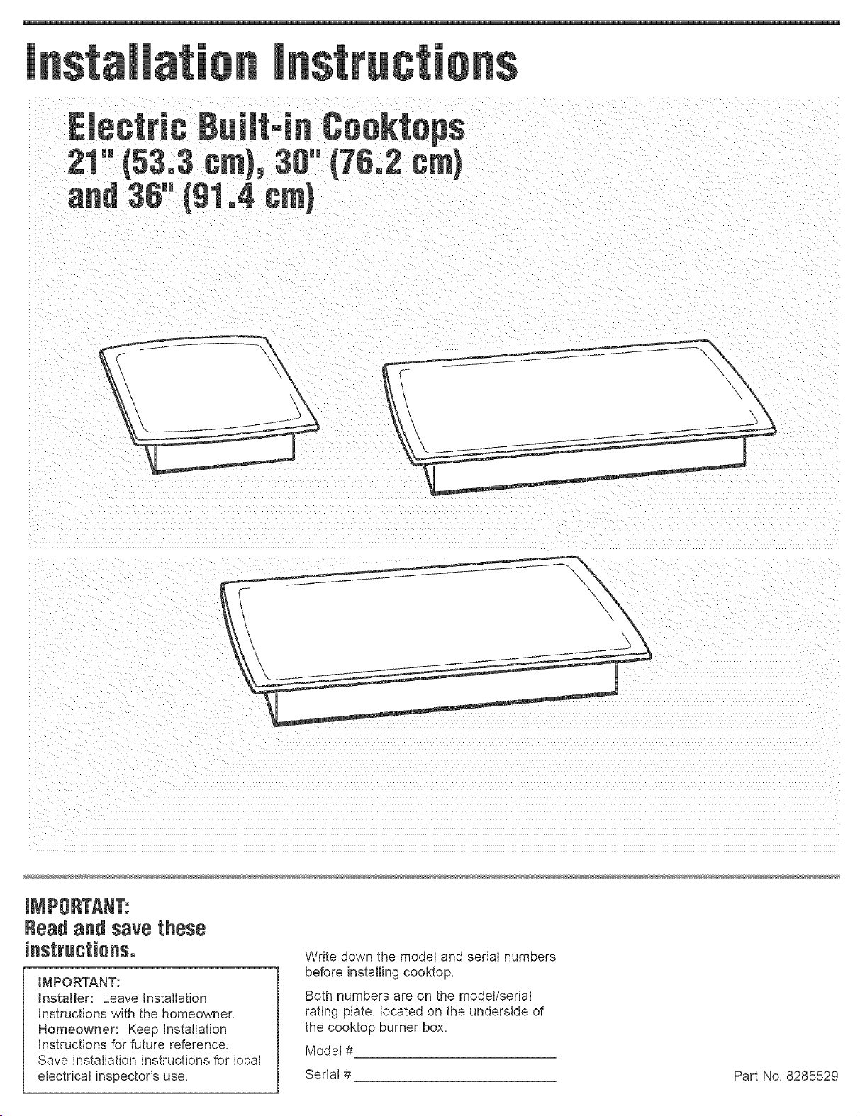
KitchenAid KECS100GSS02, RCS3014LS0, RCS3014LT0, RCS3014LB0, RCS3614LB0 Installation Guide
...Page 1
e
\
Read and sa_e these
IMPORTANT:
Installer: Leave Installation
Instructions with the homeowner.
Homeowner: Keep Installation
Instructions for future reference.
Save installation Instructions for local
electrical inspector's use.
Write down the model and serial numbers
before installing cooktop.
Both numbers are on the model/serial
rating plate, located on the underside of
the cooktop burner box.
Model #
Serial #
Part No, 8285529
Page 2
Before youstart,,,
Your safety and the safety of
others are very important.
We have provided many important
safety messages in this manual and
on your appliance. AKuays read and
obey all safety messages.
This is the safety alert
symbol.
This symbol alerts you to
potential hazards that can kill or hurt
you and others.
All safety messages will follow the
safety alert symbol and either the
word "DANGER" or "WARNING".
These words mean:
You can be killed or seriously
injured if you don't immediateIx
follow instructions.
You can be killed or seriously
injured if you don't follow
instructions.
All safety messages will tell you
what the potential hazard is, tell you
how to reduce the chance of injury,
and tell you what can happen if the
instructions are not followed.
important: Observe all governing
codes and ordinances.
To eliminate the risk of burns by
reaching over heated surface units,
cabinet storage space located above
the surface units should be avoided. If
cabinet storage is to be provided, the
risk can be reduced by installing a
range hood that projects horizontally a
minimum of 5 inches (12.7 cm) beyond
the bottom of the cabinets.
Proper installation is your responsibility
Make sure you have everything for
correct installation. It is the
responsibility of the installer to comply
with the installation clearances
specified in these instructions.
Cooktop installed over oven
installation: Only certain specified
cooktop and oven models are approved
for cooktop over oven installations.
Cooktops approved for this type of
installation will have an approval label
located on the outside of the burner
box. if you do not find this label, contact
your dealer to confirm that cooktop is
approved. The label on the bottom of
your cooktop lists the cooktop and oven
combinations that are approved for this
type of installation.
Ovens approved for this type of
installation will have an approval label
located on top of oven. If you do not
find this label, contact dealer to confirm
that oven is approved. Refer to oven
manufacturer's Installation Instructions
for approval for built-under use and
proper cutout dimensions.
When installing cooktop over a built-
under oven, Do not fasten cooktop to
countertop with clamps. Cooktop then
will be easy to remove if servicing is
ever necessary.
Check location where cooktop will be
installed. The location should be away
from strong draft areas, such as
windows, doors and strong heating
vents or fans. The cooktop should be
located for convenient use in the
kitchen.
Grounded electrical suppmy is
required. See "Electrical requirements,"
Page 4.
important:
Observe aH governing codes and
ordinances.
When installing a cooktop under
existing cabinets and the installation
does not meet the minimum cabinet
clearances, install a range hood above
the cooktop to avoid burn hazards.
Countertop opening dimensions that
are shown must be used. Given
dimensions are minimum clearances
and provide required 0" (0 cm)
clearance.
Replacement installations -- follow
minimum dimensions given.
It is the customer's responsibility:
To contact a qualified electrical installer.
To assure that the electrical installation
is adequate and in conformance with
National Electrical Code, ANSI/NFRA
70 -- latest edition**, or CSA
Standards
C22.1-94, Canadian Electrical Code,
Part 1 and C22.2 No. 0-M91 - latest
edition *** and aH local codes and
ordinances.
Copies of the standards listed may be obtained
from:
* National Fire Protection Association
Batterymarch Park
Quincy', Massachusetts 02269
** CSA htemationat
8501 East Pmeasant Valley Road
C_eveland, Ohio 44131-5575
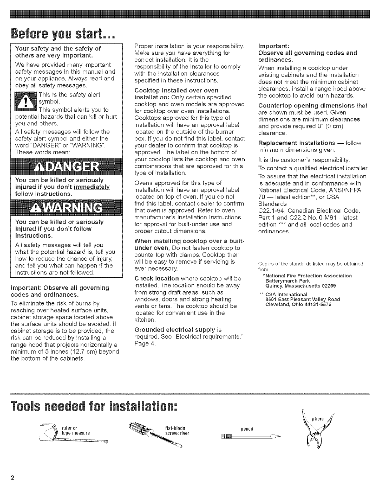
neededfor
_'_wdriver
fiat=blade
_ pliers/_'
pencil
Page 3
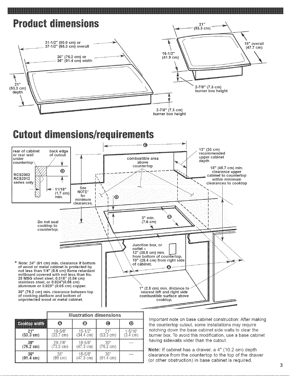
Product dimendens
314/2" (80.0 cm) or
37-1/2" (95.3 cm} overall
(53.3 cm)
depth
Cutoutdimendons/reqeirements
rear of cabinet back edge
or rear wall of cutout
under
eounterto
RCS2002
@
_=
18" overall
(47.7 cm)
2-7/8" (73 cm)
burner box height
2o7/8" (7.3 cm)
burner box height
t3" (33 cm)
series only
Rcs2of2 L _=
Do not seal
cooktop to
countertop.
* Note: 24" (61 cm) rain. clearance if bottom
of wood or meta_ cabinet is protected by
not less than 1/4" (0.8 cm) flame retardant
mil_board covered with not less than No.
28 MSG sheet steel, 0.018" (0.04 era)
staiNess steel or 0.024"(0.00 cm}
alumninum or 0.020" (0.08 cm) copper.
30" (78.2 cm) rain. clearance between top
of cooking platform and bottom of
unprotected wood or metal cabinet.
11/16"
/1.7 cm}
rain.
See
NOTE'
for @
minimum
clearances.
Hlustration dimensions
Q
21" 1-5/16"
(53.3 era) (3.4 cra)
38"
(76.2 era)
36"
(gl.4 era)
18-5/8"
(33.7 cra)
28-7/8"
(73.3 cra)
35"
(89 cra)
O @
15-1/2" 21"
(34.4 cra) (53.3 cm)
18-5/8" 30"
(47.3 cra) (76.2 cm)
18-5/8" 36"
(47.3 cm) (91.4 cm)
Junction box, or
outlet =
12" (30.8 cm) rain.
from bottom of countertop.
10" (28.4 cm) from right side
of cabinet.
1" (2.8 cm) rain.
nearest left and right side
eombustiNe surface above
@
Important note on base cabinet construction: After making
the countertop cutout, some installations may require
U
cooktop.
notching down the base cabinet side walls to clear the
burner box. To avoid this modification, use a base cabinet
having side/vails wider than the cutout.
Note: if cabinet has a drawer, a 4" (10.2 cm) depth
clearance from the countertop to the top of the drawer
(or other obstruction) in base cabinet is required.
Page 4

if codespermitandaseparateground
wireisused,itisrecommendedthata
qualifiedelectriciandeterminethatthe
groundpathandwiregaugearein
accordancewithlocalcodes.
DoNotgroundtoagaspipe.
Checkwithaqualifiedelectricianifyou
arenotsurethecooktopisproperly
grounded.
DoNothaveafuseintheneutralor
groundcircuit.
Thiscooktopmustbeconnectedtoa
metalpermanentwiringsystem.
IMPORTANT:
SaveInstallationInstructionsfor
electricalinspector'suse.
240-volt cooktop
A E A three-wire or four-wire, single
phase, 240-volt, 60-Hz, AC-only
electrical supply is required on a
separate, 40-ampere circuit (note: the
RCS2012 series requires a 20 ampere
circuit), fused on both sides of the line.
A time-delay fuse or circuit breaker is
recommended. The fuse size must not
exceed the circuit rating of the
appliance specified on the modeVserial
rating plate located on the bottom of
the cooktop.
BE Wire sizes and connections
must conform to the requirements of
the National Electrical Code
ANSI/NFPA 70 - latest edition*, or CSA
Standards C22.1-94, Canadian
Electrical Code, Part 1 and C22.2 No.
0-M91 - latest edition** and all local
codes and ordinances.
O E The cooktop should be
connected directly to the fused
disconnect or circuit breaker box
through flexible, armored or non-
metallic sheathed, copper cable. The
flexible, armored cable extending from
the fuse box or circuit breaker box
should be connected directly to the
junction box.
E Locate the junction box to allow
as much slack as possible between the
junction box and the cooktop so that
the cooktop can be moved if
servicing is ever necessary. Do Not cut
the conduit.
E m A U.L- or CSAqisted conduit
connector must be provided at each
end of the power supply cable (at the
cooktop and at the junction box.)
FE If the house has aluminum wiring,
follow the procedure below:
a.) Connect the aluminum wiring to the
copper wire by using special
connectors designed and
Underwriters Laboritoriesqisted for
joining copper to aluminum. Follow
the electrical connector
manufacturer's recommended
procedure.
b.) Aluminum/copper connection must
conform with local codes and
industry-accepted wiring practices.
120-volt cooktop
A 120-volt, 60-Hz, AC-only, 20-ampere,
fused electrical supply is required.
(Time-delay fuse or circuit breaker is
recommended.) It is recommended
that a separate circuit serving only this
appliance be provided. A NEMA 5-
20R, 3-prong ground-type outlet must
be used.
Electrical Shock Hazard
Plug into a grounded 3-prong
outlet.
Do not remove ground prong.
Do not use an adapter.
Do not use an extension cord.
Failure to follow these instructions
can result in death, fire, or
electdca_ shock.
equipped with a power supply cord
having a NEMA 5-20R 3-prong ground
plug. To minimize possible shock
hazard, the cord must be plugged into a
mating, NEMA 5-20R, 3-prong ground-
type outlet, grounded in accordance
with the National Electrical Code,
ANSI/NFPA 70 -- latest edition*, and
local codes and ordinances. (See
Figure 1.)
If a mating outlet is not available, it is
the personal responsibility and
obligation of the customer to have a
properly grounded, NEMA 5-20R,
3-prong outlet installed by a qualified
electrician.
WARNING - Improper connection of the
equipment-grounding conductor can
result in a risk of electric shock. Check
with a qualified electrician or
serviceman if you are in doubt as to
whether the appliance is properly
grounded. Do not modify the plug
provided with the appliance - if it wiJJnot
fit the outlet, have a proper outlet
installed by a qualified electrician.
Copies of the standards listed above may be
obtained from:
* National Fire Protection Association
Batterymarch Park
Quincy, Massachusetts 02259
** CSA htemationat
8501 East Pleasant Valley Road
C_eveland, Ohio 44131-5575
Recommended ground
method
For your personal safety, this cooktop
must be grounded. This cooktop is
Page 5

3. Connect the green (or bare)
4. Connect the two black wires together;
ElectricalShockHazard
Disconnectpower before
servicing.
Electrically ground cooktop.
permit connecting the frame-ground
conductor to the neutral (white) junction
box wire: (Used for all Canadian
installations)
Failure to follow these instructions
can result in death, fire, or
electrical shock.
This cooktop must be connected to a
grounded, metallic permanent wiring
system or a ground connector should
be connected to the ground terminal or
wire lead on the cooktop.
This cooktop is manufactured with a
frame connected, green or bare ground
wire. Connect the cooktop cable to the
junction box through the U.L.- or CSA-
bare or green _--_..J_ _"
w,res \ o JCs.2.j,2;e
listed conduit connector. Complete
electrical connection according to local
codes and ordinances.
Ungrounded neutral- Figure 3
1. Disconnect power supply.
2. Connect the flexible, armored cable
Am Where local codes permit
connecting the frame-ground conductor
to the neutral (white) junction box wire:
(Not used for Canadian installations)
cable from power supply
red wires /_.__L /junct,on bo×
3. Connect the two black wires together;
4. Connect the green or bare ground
& Put a twist-on connector on end of
w°,,ew,reS %-y d ackw,rea
bareor. /
greeow,reJ \
cable from cooktop _ conduit connector
Grounded neutral - Figure 2
1. Disconnect power supply.
2. Connect the flexible, armored cable
from the cooktop to the junction box
using a U.L.=or CSA=listed conduit
jJJ--_;;_ U.L,o or C,SA.- listed
connector. Tighten screws on conduit
connector.
appliance cable wire with the neutral
(white) wire in the junction box using
twist=on connector.
then connect the two red wires
together with twist=on connector. (See
Figure 2.)
m Where local codes Do Not
cable from power supply
_/'_"J_ 71 J '_black wires
cable from cooktop
from the cooktop to the junction box
using a U.L.- or CSAqisted conduit
connector. Tighten screws on conduit
connector.
then connect the two red wires
together using twist-on connector.
(See Figure 3.)
wire from the appliance cable to the
grounded wire in the junction box or
other grounded connector using twist-
on connector.
white wire.
Nowstart...
With cooktop in kitchen.
Excessive Weight Hazard
Use two or more people to move
and install cooktop.
Failure to do so can result in back
or other injury.
m Remove the shipping materials
and tape from the cooktop. Remove the
hardware package from inside the
literature bag.
attachment screws
for optiona_ front _ burner box
and back location bottom
attachment /
/ screw
bracket (end
_ocations F
"U" shaped spring
clipor sma_
diameter hole
Standard cooktop shown. See specific
instructions for installing brackets on Lift Yop
models.
m Two clamp brackets are provided
to clamp the cooktop to the countertop.
Install the clamp brackets on each end
of the burner box bottom. Optional: If
cabinet construction does not provide
clearance for installing brackets at
burner box ends, install the brackets on
the front and back of the burner box
bottom.
The brackets may be installed before
(see Step 2a) or after (see Step 2b) the
cooktop is placed into the cutout. Note:
Step 2B is not recommended for Lift
Top models.
a m If installing before the
cooktop is placed into cutout:
• Remove elements and burner bowls.
• Place the cooktop upside down on a
protective surface (blanket, pad). For
Lift Top models: Place the cooktop
right side up on the protective surface.
Page 6

• Removetheattachmentscrewsforthe
bracketlocationsselectedfromthe
bottomoftheburnerbox.ForLiftTop
models:Removethetwophillips
roundheadscrewsandhexnutsfrom
theenvelope.
• Usebracketmountingholesthatwill
allowtheclampscrews(seeStep3)
tocontactthecountertopbottom.
Attachbracketsas shownthenrotate
bracketssothattheydonotextend
beyondedgeof burnerbox.
ForLiftTop
models:Lifttop
(seeUseandCare
Guidefor
instructions)and
installroundhead
screwsthroughthe
burnerboxand
bracketssothatthe
screwheadisinsidetheburnerbox.
Attachthehexnutsagainstclamp
brackets.
•Tightenscrews(orhexnuts)just
enoughtoholdbracketsinplace
whencooktopisputintocutout.
•Turnthecooktoprightsideupif
needed.Carefullyplaceintothe
cutout,important:Checkthatthefront
edgeof thecooktopisparaJieltothe
frontedgeofthecountertop.
ifrepostioningisneeded,liftentire
cooktopupfromcutouttoprevent
scratchingthecountertop.
• Loosenthescrewsornuts,rotatethe
bracketssothattheyextendbeyond
edgeof theburnerbox.Tighten
screwsornutssecurely.
If installing after the cooktop
is placed into cutout (Note: This method is
not recommended for Lift Top models.):
• Carefully place cooktop into cutout.
• important: Check that the front edge
of the cooktop is parallel to the front
edge of the countertop.
if repostioning is needed, lift entire
cooktop up from cutout to prevent
scratching the countertop.
• Remove the attachment screws from
selected bracket locations on the
bottom of the burner box.
• Attach brackets as shown so that they
are beyond edge of burner box and
the clamp screws (see Step 3) will
contact the countertop bottom.
Tighten screws securely.
Part No. 8285529
@2003Whirlpool Corporation
ccektcp cmmtertcp
box slamping
bracket
3m Place the 2=1/2" (6.4 cm)
clamping screws into the brackets. Use
a screwdriver to tighten the screws
against the countertop. DO NOT
OVERTIGHTEN.
4E Make electrical connection. (See
"Electrical requirements" and "Electrical
connection" sections, Pages 4 and 5.)
If your house has aluminum wiring, see
"Electrical requirements", Page 4.
switch box
& cover.
UFT TOP MODELS (KECSI00 &
KECS161) only
Raise cooktop per Use & Care Guide
instructions. This will ensure that enough
slack is left after electrical connection to
properly operate lift top feature of cooktop.
If installing cooktop over built=under oven,
check that cooktop lift top feature operates
after oven installation is complete.
5m Reinstall elements and burner
bowls. Turn on power supply.
6m Depending on your model, push
in and turn each control knob to the "HI"
position or touch "ON" and turn each
control knob to the "HI" position. Check
the operation of the cooktop elements
and indicator lights.
Benton Harbor, Michigan 49022
attachment screw
screw
If ceektep
aet eperate:
[_ Check that the circuit breaker is not
tripped or the house fuse blown.
[_ Check that the power supply cord is
plugged into the outlet (120 V models).
[_See Use and Care Guide for
troubleshooting list.
Note: Refer to Use and Care Guide for
operating and cleaning instructions.
Jfyouneed
If you have questions about operating,
cleaning or maintaining your cooktop:
Refer to Use and Care Guide,
[]
Call the Customer Interaction Center.
Check your Use and Care Guide for
a toll-free number to call or call the
dealer from whom you purchased
this appliance. The dealer is listed in
the Yellow Pages of your phone
directory under "Appliances --
Household -- Major -- Service and
Repair."
Maintain the quality built into your
cooktop by calling an authorized
service company.
To obtain the name and number of the
authorized service company:
[_ Contact the dealer from whom you
purchased your cooktop; or
[_ Look in the Yellow Pages of your
telephone directory under
"Appliances -- Household --
Major -- Service and Repair;" or
[_ Call the Customer Interaction Center.
The toll4ree number is listed in your
Use and Care Guide.
When you call, you will need:
[_The cooktop model number.
[_The cooktop serial number.
Both numbers are listed on the
model/serial rating plate located on the
underside of cooktop burner box.
Printed in U.S.A.
 Loading...