

KitchenAid KECS161GWH0, KECS161GSS0, KECS100GWH0, KECS161GBL0, KECS100GBL0 Installation Guide
...
Piecen°3191538Rev.A
Part No. 3191538 Rev. A
Tables de cuisson dlectriques
encastrdes de 76,2 cm (30 po)
IMPORTANT ."
Lire et conserver
ces instructions.
IMPORTANT :
Installateur : Remettre les instructions d'installation au proprietaire.
Propri_taire : Conserver les instructions d'installation pour reference ulterieure.
Conserver les instructions d'installation pour utilisation par I'inspecteur local
des installations electriques.
Inscrire les numeros de modele et de serie avant d'installer la table de
cuisson.
Les deux numeros sont indiques sur la plaque signaletique des numeros de
modele et de serie, situee au fond de la table de cuisson.
N° de modele N° de serie
30" (76.2 cm), 36" (91.4 cm), and
21" (53.3 cm) Electric
Built-in Cooktops
IMPORTANT:
Read and save these
instructions.
IMPORTANT:
Installer: Leave Installation Instructions with the homeowner.
Homeowner: Keep Installation Instructions for future reference.
Save Installation Instructions for local electrical inspector's use.
Write down the model and serial numbers before installing cooktop.
Both numbers are on the model/serial rating plate, located on the bottom of
the cooktop.
Model # Serial #
Before you start...
Yoursafety and the safety of others
isvery important.
We haveprovided manyimportant safety messages
in this manualand on your appliance,Always read
and obeyall safety messages,
This is the safety alert symbol. This symb01
alerts you to hazardsthatcan kill or hurt
you and others, Ati safety messageswiii be
precededby the safety aiert symbol andthe word
"DANGER"or "WARNING",Thesewords mean:
Youca_ be killed or seri0usly injuredif you don't
f0110winstructi0ns.
AIi safety messageswiii identify the hazard,teii y0u
how to reducethe chance of injury, and teli y0u
what can happenif the instructions are not
followed.
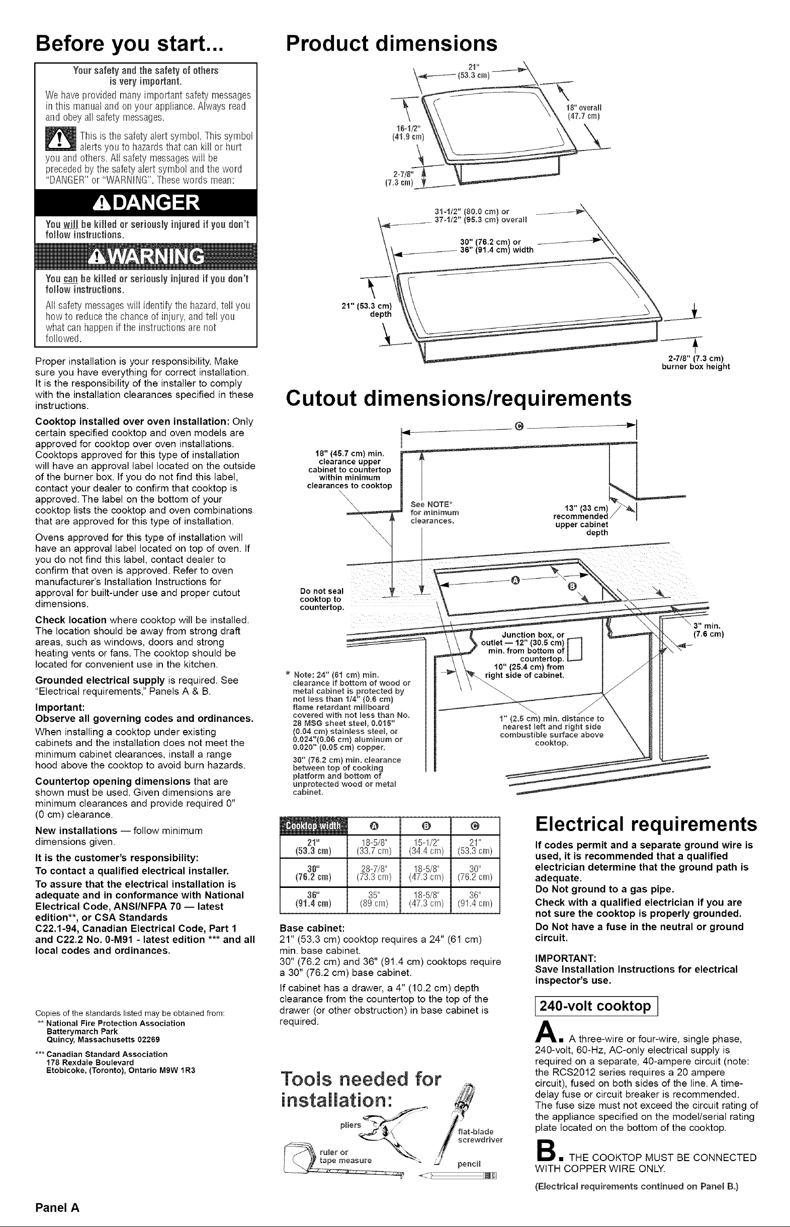
Product dimensions
18" 0retail
(47,7 cm)
2=7/8"
(7.3Gin)
31=112" (80.0 cm) or
(98.3 cm) overall
30" (76.2 cm) or
(91.4 cm) width
21" (53.3 cm)
depth
Proper installation is your responsibility. Make
sure you have everything for correct installation.
It is the responsibility of the installer to comply
with the installation clearances specified in these
instructions.
Cooktop installed over oven installation: Only
certain specified cooktop and oven models are
approved for cooktop over oven installations.
Cooktops approved for this type of installation
will have an approval label located on the outside
of the burner box. If you do not find this label,
contact your dealer to confirm that cooktop is
approved. The label on the bottom of your
cooktop lists the cooktop and oven combinations
that are approved for this type of installation.
Ovens approved for this type of installation will
have an approval label located on top of oven. If
you do not find this label, contact dealer to
confirm that oven is approved. Refer to oven
manufacturer's Installation Instructions for
approval for built-under use and proper cutout
dimensions.
Check location where cooktop will be installed.
The location should be away from strong draft
areas, such as windows, doors and strong
heating vents or fans. The cooktop should be
located for convenient use in the kitchen.
Grounded electrical supply is required. See
"Electrical requirements," Panels A & B.
Important:
Observe all governing codes and ordinances.
When installing a cooktop under existing
cabinets and the installation does not meet the
minimum cabinet clearances, install a range
hood above the cooktop to avoid burn hazards.
Countertop opening dimensions that are
shown must be used. Given dimensions are
minimum clearances and provide required 0"
(0 cm) clearance.
New installations -- follow minimum
dimensions given.
It is the customer's responsibility:
To contact a qualified electrical installer.
To assure that the electrical installation is
adequate and in conformance with National
Electrical Code, ANSI/NFPA 70 -- latest
edition**, or CSA Standards
C22.1-94, Canadian Electrical Code, Part 1
and C22.2 No. 0-M91 - latest edition *** and all
local codes and ordinances.
Copies of the standards listed may be obtained from:
** National Fire Protection Association
Batterymarch Park
Quincy, Massachusetts 02269
*** Canadian Standard Association
178 Rexdale Boulevard
Etobicoke, (Toronto), Ontario M9W 1R3
Cutout dimensions/requirements
18" (46.7 cm) min.
clearance upper
cabinet to countertop
within minimum
clearances to cooktop
\,
Do not seal
cooktop to
countertop,
Junction box, or
outlet -- 12" (30.6 cm) [_
min. from bottom of I 1
* Note: 24" (61 cm) rain.
clearance if bottom of wood or
meta_ cabinet is protected by
not less than t/4" (0.6 era}
flame retardant miHboard
covered with not messthan No.
28 MeG sheet steel, 6.016"
(0.04 cm) stainless steel or
0.624"(6.66 cm) aluminum or
0.626" (0.65 cm) copper.
36" (76.2 cm) rain. clearance
between top of cooking
platform and bottom of
unprotected wood or meta_
cabinet.
right side of cabinet.
Q O @
21" 18-5/8" 15-1/2" 21"
(53.3era) (33.7cm) (34.4crn) (53.3crn)
30" 28-7/8" !8-5/8" 30"
(76.2era) (73.3cm) (47.3crn) (76.2crn)
30" 35" 18-5/8" 30"
(01.4era) (89cm) (47.3crn) (91.4crn)
Base cabinet:
21" (53.3 cm) cooktop requires a 24" (61 cm)
min. base cabinet.
30" (76.2 cm) and 36" (91.4 cm) cooktops require
a 30" (76.2 cm) base cabinet.
If cabinet has a drawer, a 4" (10.2 cm) depth
clearance from the countertop to the top of the
drawer (or other obstruction) in base cabinet is
required.
Tools needed for
installation:
p_iers
fiat=blade
screwdriver
ru'eror
countertop. L.=..J
10" (26.4 cm) from
\ Y
1" (2.5 cm) rain. distance to
nearest left and right side
combustible surface above
cooktop.
Electrical requirements
If codes permit and a separate ground wire is
used, it is recommended that a qualified
electrician determine that the ground path is
adequate.
Do Not ground to a gas pipe.
Check with a qualified electrician if you are
not sure the cooktop is properly grounded.
Do Not have a fuse in the neutral or ground
circuit.
IMPORTANT:
Save Installation Instructions for electrical
inspector's use.
240-volt cooktop
A= A three-wire or four-wire, single phase,
240-volt, 60-Hz, AC-only electrical supply is
required on a separate, 40-ampere circuit (note:
the RCS2012 series requires a 20 ampere
circuit), fused on both sides of the line. A time-
delay fuse or circuit breaker is recommended.
The fuse size must not exceed the circuit rating of
the appliance specified on the model/serial rating
plate located on the bottom of the cooktop.
B= THE COOKTOP MUST BE CONNECTED
WITH COPPER WIRE ONLY.
2-7/8" (7,3 cm)
burner box height
min,
(7.6 cm)
Panel A
(Electrical requirements continued on Panel Be)
(Electricam requirements continued from PaneI A.)
C• Wire sizes and connections must conform
to the requirements of the National Electrical
Code ANSI/NFPA 70 - latest edition **, or CSA
Standards C22.1-94, Canadian Electrical Code,
Part 1 and C22.2 No. 0-M91 - latest edition ***
and all local codes and ordinances.
D• The cooktop should be connected directly
to the fused disconnect or circuit breaker box
through flexible, armored or non-metallic
sheathed, copper cable. The flexible, armored
cable extending from the fuse box or circuit
breaker box should be connected directly to the
junction box.
• Locate the junction box to allow as much
slack as possible between the junction box and
the cooktop so that the cooktop can be moved if
servicing is ever necessary. Do Not cut the
conduit.
F• A U.L.- or C.S.A.-listed conduit connector
must be provided at each end of the power
supply cable (at the cooktop and at the junction
box).
Copies of the standards listed may be obtained from:
** National Fire Protection Association
Batterymarch Park
Quincy, Massachusetts 02269
*** Canadian Standard Association
178 Rexdale Boulevard
Etobicoke (Toronto), Ontario M9W 1R3
120-volt cooktop I
A 120-volt, 60-Hz, AC-only, 20-ampere, fused
electrical supply is required. (Time-delay fuse or
circuit breaker is recommended.) It is
recommended that a separate circuit serving
only this appliance be provided. A NEMA 5-20R,
3-prong ground-type outlet must be used.
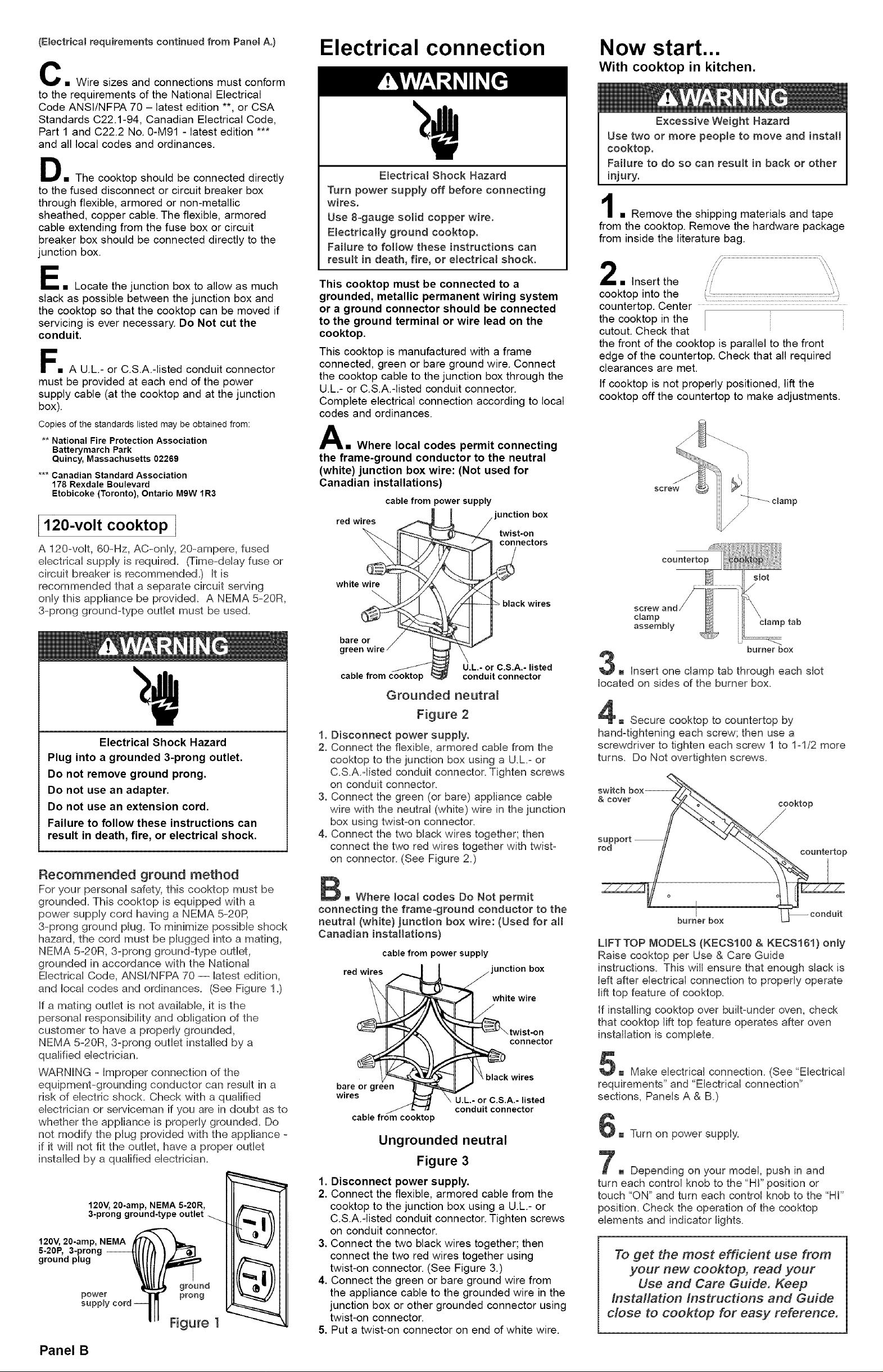
Electrical connection
Electrical Shock Hazard
Turn power supply off before connecting
wires.
Use 8=gauge solid copper wire.
Electrically ground cooktop.
Failure to follow these instructions can
result in death, fire, or emectricaI shock.
This cooktop must be connected to a
grounded, metallic permanent wiring system
or a ground connector should be connected
to the ground terminal or wire lead on the
cooktop.
This cooktop is manufactured with a frame
connected, green or bare ground wire. Connect
the cooktop cable to the junction box through the
U.L.- or C.S.A.-listed conduit connector.
Complete electrical connection according to local
codes and ordinances.
A• Where local codes permit connecting
the frame-ground conductor to the neutral
(white) junction box wire: (Not used for
Canadian installations)
cable from power supply
"unction box
twist-on
red wires
connectors
black wires
Now start...
With cooktop in kitchen.
Excessive Weight Hazard
Use two or more people to move and install
cooktop.
Failure to do so can result in back or other
injury.
• Remove the shipping materials and tape
from the cooktop. Remove the hardware package
from inside the literature bag.
• Insert the
cooktop into the .
the cooktop in the
countertop. Center
cutout. Check that
the front of the cooktop is parallel to the front
edge of the countertop. Check that all required
clearances are met.
if cooktop is not properly positioned, lift the
cooktop off the countertop to make adjustments.
"_ clamp
/
countertop
slot
clamp
assembly clamp tab
Electrical Shock Hazard
Plug into a grounded 3-prong outlet.
Do not remove ground prong.
Do not use an adapter.
Do not use an extension cord.
Failure to follow these instructions can
result in death, fire, or electrical shock.
Recommended ground method
For your personal safety, this cooktop must be
grounded. This cooktop is equipped with a
power supply cord having a NEMA 5-20R
3-prong ground plug. To minimize possible shock
hazard, the cord must be plugged into a mating,
NEMA 5-20R, 8-prong ground-type outlet,
grounded in accordance with the National
Electrical Code, ANSI/NFPA 70 -- latest edition,
and local codes and ordinances. (See Figure 1.)
If a mating outlet is not available, it is the
personal responsibility and obligation of the
customer to have a properly grounded,
NEMA 5-20R, 3-prong outlet installed by a
qualified electrician.
WARNING - Improper connection of the
equipment-grounding conductor can result in a
risk of electric shock. Check with a qualified
electrician or serviceman if you are in doubt as to
whether the appliance is properly grounded. Do
not modify the plug provided with the appliance -
if it wiii not fit the outlet, have a proper outlet
installed by a qualified electrician.
120V, 20-amp, NEMA 5-20R,
3-prong ground-type outlet
120V, 20-amp, NEMA
5-20P, 3-prong --
ground plug
power
su groun( _
prong
Figure 1
;iii
U.L.- or C.S.A,- listed
conduit connector
Grounded neutra_
Figure 2
1. Disconnect power supply.
2. Connect the flexible, armored cable from the
cooktop to the junction box using a U.L.=or
C.S.A.qisted conduit connector. Tighten screws
on conduit connector.
3. Connect the green (or bare) appliance cable
wire with the neutral (white) wire in the junction
box using twist=on connector.
4. Connect the two black wires together; then
connect the two red wires together with twist=
on connector. (See Figure 2.)
B Where local codes Do Not permit
connecting the frame=ground conductor to the
neutral (white) junction box wire: (Used for atl
Canadian installations)
cable from power supply
red wires "unction box
white wire
/
connector
bare or green
wires
Ungrounded neutral
Figure 3
1. Disconnect power supply.
2. Connect the flexible, armored cable from the
cooktop to the junction box using a U.L.- or
C.S.A.-listed conduit connector. Tighten screws
on conduit connector.
3. Connect the two black wires together; then
connect the two red wires together using
twist-on connector. (See Figure 3.)
4. Connect the green or bare ground wire from
the appliance cable to the grounded wire in the
junction box or other grounded connector using
twist-on connector.
5. Put a twist-on connector on end of white wire.
U,L,- or C.S,A,- listed
conduit connector
P
burner box
3m Insert one clamp tab through each slot
located on sides of the burner box.
E Secure cooktop to countertop by
hand=tightening each screw; then use a
screwdriver to tighten each screw 1 to 1=1/2 more
turns. Do Not overtighten screws.
rsupp°rt // "/"_.. _-_',_\
burn_er box _ conduit
UFTTOP MODELS (KECS100 & KECS161) only
Raise cooktop per Use & Care Guide
instructions. This will ensure that enough slack is
left after electrical connection to properly operate
lift top feature of cooktop.
If installing cooktop over built=under oven, check
that cooktop lift top feature operates after oven
installation is complete.
5m Make electrical connection. (See *'Electrical
requirements" and "Electrical connection"
sections, Panels A & B.)
6m Turn on power supply.
7m Depending on your model, push in and
turn each control knob to the *'HI"position or
touch *'ON"and turn each control knob to the *'HI"
position. Check the operation of the cooktop
elements and indicator lights.
To get the most efficient use from
your new cooktop, read your
Use and Care Guide. Keep
Installation instructions and Guide
close to cooktop for easy reference.
Panel B
 Loading...