

KitchenAid KECD867XSS01, KECD867XSS00, KECD807XSS00, KECD807XBL00, KECD867XBL01 Installation Guide
...Page 1
30" (76.2 CM) AND 36" (91.4 CM) ELECTRIC
DOWNDRAFT COOKTOP
INSTALLATIONINSTRUCTIONS
INSTRUCTIONSD'INSTALLATIONDE LATABLEDE
CUISSON ELECTRIQUEAVEC ASPIRATION
PARLEBASDE30" (76,2 CM) ET36" (91,4 CM)
TableofContents/Tabledesmah_res
COOKTOP SAFETY ........................................................................ 2
INSTALLATION REQUIREMENTS ................................................ 3
Tools and Parts ............................................................................ 3
Location Requirements ................................................................ 3
Venting Requirements .................................................................. 5
Venting Methods .......................................................................... 6
Electrical Requirements .............................................................. 8
INSTALLATION INSTRUCTIONS .................................................. 9
Prepare Cooktop .......................................................................... 9
Install Foam Strip .......................................................................... 9
Rotate Blower - Optional .............................................................. 9
Install Cooktop ........................................................................... 11
Make Electrical Connection ....................................................... 11
Complete Installation .................................................................. 12
SleCURITle DE LA TABLE DE CUlSSON ................................. 13
EXIGENCES D'INSTALLATION ................................................ 14
Outils et pieces ........................................................................ 14
Exigences d'emplacement ...................................................... 14
Exigences concernant I'evacuation ........................................ 16
Methodes d'evacuation ........................................................... 17
Specifications electriques ....................................................... 19
INSTRUCTIONS D'INSTALLATION ......................................... 20
Preparation de la table de cuisson ......................................... 20
Installation de la bande de mousse ........................................ 20
Rotation du ventilateur- Facultative ....................................... 20
Installation de la table de cuisson ........................................... 22
Raccordement electrique ........................................................ 22
Achever I'installation ............................................................... 23
iMPORTANT:
Save for local electrical inspector's use.
iMPORTANT :
,&,conserver pour consultation par I'inspecteur local des installations 61ectriques.
W10298568A
Page 2
COOKTOP SAFETY
Your safety and the safety of others are very important.
We have provided many important safety messages in this manual and on your appliance. Always read and obey all safety
messages.
This is the safety alert symbol.
This symbol alerts you to potential hazards that can kill or hurt you and others.
All safety messages will follow the safety alert symbol and either the word "DANGER" or "WARNING."
These words mean:
You can be killed or seriously injured if you don't immediately
follow instructions.
You can be killed or seriously injured if you don't follow
instructions.
All safety messages will tell you what the potential hazard is, tell you how to reduce the chance of injury, and tell you what can
happen if the instructions are not followed.
2
Page 3
INSTALLATIONREQUIREMENTS
Gather the required tools and parts before starting installation.
Read and follow the instructions provided with any tools listed
here.
Tools needed
• Tape measure
• Flat-blade screwdriver
• Phillips head screwdriver
• Drill
• Level
• 6" socket extension
Parts supplied
• Vent grille
• Pre-filter
Parts needed
• A UL listed or CSA approved strain relief for 7/8"(2.2 cm)
knockout.
• A UL listed or CSA approved conduit connector for
1/2"(1.3 cm) trade-size metal-clad conduit
• UL listed wire connectors
Metal ducting
Wall cap
6" (15.2 cm) Round Surface Wall Cap Damper
Order Part Number A406
5" (12.7 cm) Round Surface Wall Cap Damper
Order Part Number A405
31¼"x 10" (8.3 x 25.4 cm) Surface Wall Cap Damper
Order Part Number A403
To order, see the "Assistance or Service" section of the Use
and Care Guide.
• Vent clamps
Check local codes. Check existing electrical supply. See
"Electrical Requirements" section.
It is recommended that all electrical connections be made by a
licensed, qualified electrical installer.
IMPORTANT: Observe all governing codes and ordinances.
When installing cooktop, use minimum dimensions given.
• To eliminate the risk of burns or fire by reaching over the
heated surface units, cabinet storage space located above
the surface units should be avoided. If cabinet storage is to
be provided, the risk can be reduced by installing a range
hood that projects horizontally a minimum of 5" (12.7 cm)
beyond the bottom of the cabinets.
• Use the countertop opening dimensions that are given with
these Installation Instructions. Given dimensions are
minimum clearances and provide 0" (0 cm) clearance.
• Marker or pencil
• Pliers
• 1¼.drill bit
• Jigsaw
• Ratchet with 3/8"socket
• Grounded electrical supply is required. See "Electrical
Requirements" section.
• If cabinet has drawers, drawers will need to be removed and
drawer fronts installed on front of cabinet.
IMPORTANT: An under-counter built-in oven cannot be installed
under this product.
Product Dimensions
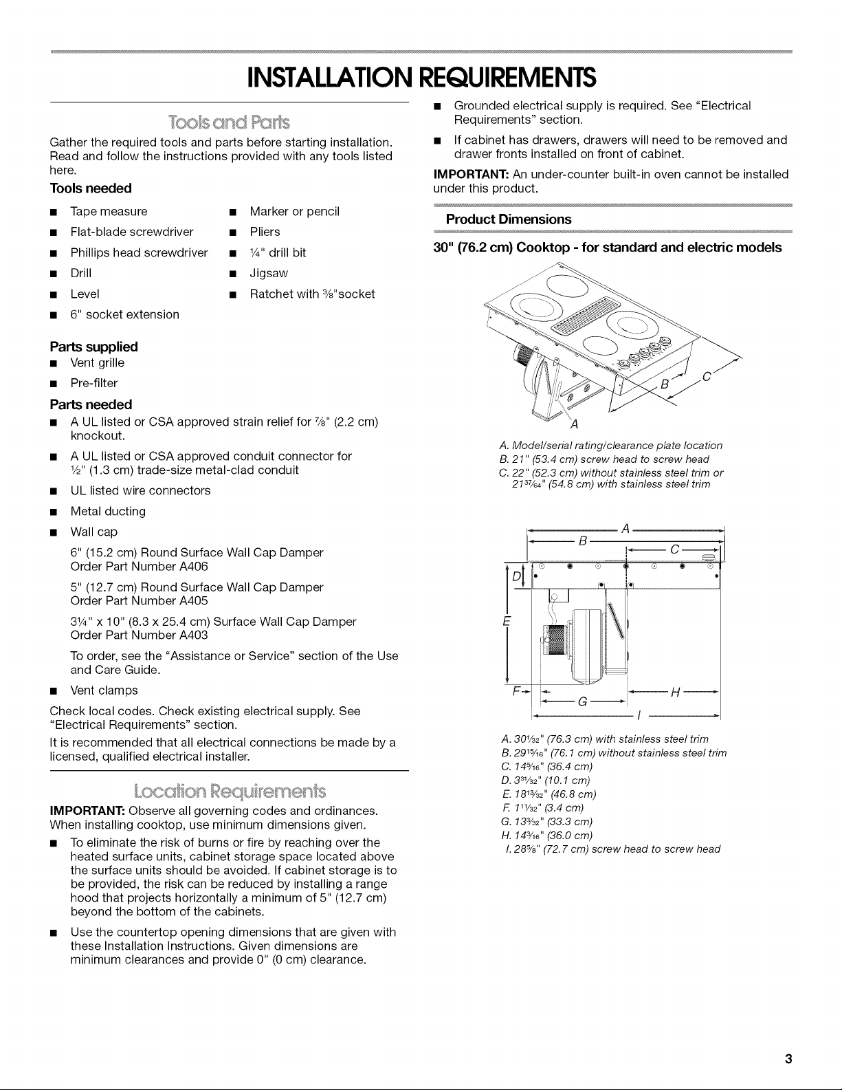
30" (76.2 cm) Cooktop - for standard and electric models
A. Model/serial rating/clearance plate location
B. 21" (53.4 cm) screw head to screw head
C. 22" (52.3 cm) without stainless steel trim or
21s7/64''(54.8 cm) with stainless steel trim
i C--------_
@ ® ©
E
J
F_ i_ i_-.------------J-H
i_--G i
A.30½_"(76.3 cm) with stainless steel trim
B.291%6'' (76.1 cm)without stainless steel trim
C. 14%d'(36.4 cm)
D. 331/32 '' (10.1 cm)
E.1813/32''(46.8 cm)
F. 1_½_'' (3.4cm)
G. 13s/3_'' (33.3 cm)
H. 14s/le''(36.0 cm)
I.28%" (72.7cm) screw head to screw head
Page 4
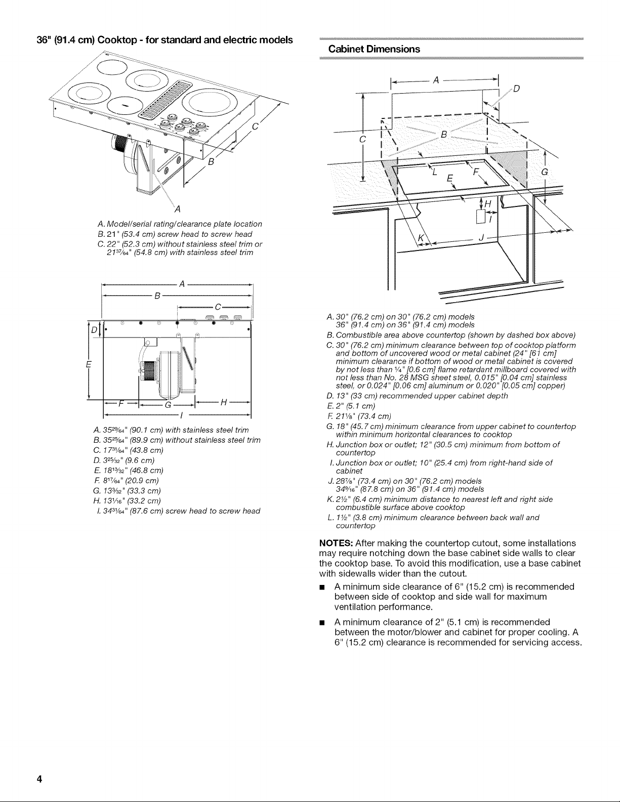
36" (91.4 cm) Cooktop -for standard and electric models
A. Model/serial rating/clearance plate location
B. 21" (53.4 cm) screw head to screw head
C. 22" (52.3 cm) without stainless steel trim or
2137/64'' (54.8 cm) with stainless steel trim
A =r
B
A. 35_%4'' (90.1 cm) with stainless steel trim
B. 35_%4" (89.9 cm) without stainless steel trim
C, 1 731/64 '' (43.8 cm)
D. 3_%_'' (9.6 cm)
E. 1813/32'' (46.8 cm)
F. 817/64 '' (20,9 cm)
G. 133/32" (33.3 cm)
H. 131/16'' (33.2 cm)
I.3431/64'' (87.6 cm) screw head to screw head
Cabinet Dimensions
C
A. 30" (76.2 cm) on 30" (76.2 cm) models
36" (91.4 cm) on 36" (91.4 cm) models
B. Combustible area above countertop (shown by dashed box above)
C. 30" (76.2 cm) minimum clearance between top of cool(top platform
and bottom of uncovered wood or metal cabinet (24" [61 cm[
minimum clearance if bottom of wood or metal cabinet is covered
by not less than 1/4"[0.6 cm] flame retardant millboard covered with
not less than No. 28 MSG sheet steel, 0.015" [0.04 cm] stainless
steel, or 0.024" [0.06 cm] aluminum or 0.020" [0.05 cm] copper)
D. 13" (33 cm) recommended upper cabinet depth
E.2"(5.1 cm)
F. 211/8'' (73.4 cm)
G. 18" (45. 7cm) minimum clearance from upper cabinet to countertop
within minimum horizontal clearances to cool(top
H. Junction box or outlet; 12" (30.5 cm) minimum from bottom of
countertop
I. Junction box or outlet; 10" (25.4 cm) from right-hand side of
cabinet
J. 287/8'' (73.4 cm) on 30" (76.2 cm) models
349/18''(87.8 cm) on 36" (91.4 cm) models
K. 2V2" (6.4 cm) minimum distance to nearest left and right side
combustible surface above coot(top
L. 1V2" (3.8 cm) minimum clearance between back wall and
countertop
NOTES: After making the countertop cutout, some installations
may require notching down the base cabinet side walls to clear
the cooktop base. To avoid this modification, use a base cabinet
with sidewalls wider than the cutout.
• A minimum side clearance of 6" (15.2 cm) is recommended
between side of cooktop and side wall for maximum
ventilation performance.
• A minimum clearance of 2" (5.1 cm) is recommended
between the motor/blower and cabinet for proper cooling. A
6" (15.2 cm) clearance is recommended for servicing access.
Page 5
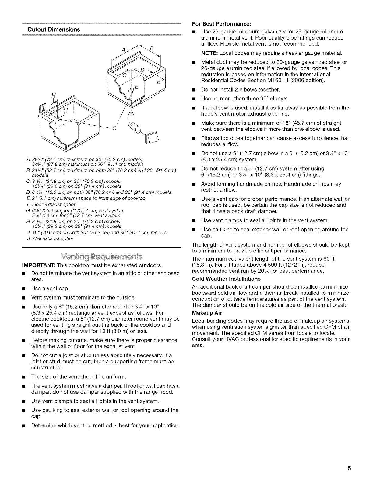
Cutout Dimensions
A B
H
A. 28%" (73.4 cm) maximum on 30" (76.2 cm) models
34%6" (87.8 cm) maximum on 36" (91.4 cm) models
B. 211/8'' (53.7 em) maximum on both 30" (76.2 em) and 36" (91.4 em)
models
C. 81%=''(21.8 em) on 30" (76.2 em) models
157/16''(39.2 em) on 36" (91.4 em) models
D. 61%4'' (16.0 em) on both 30" (76.2 em) and 36" (91.4 em) models
E. 2" (5.1 em) minimum space to front edge of eooktop
F. Floor exhaust option
G. 61/s'' (15.6 em) for 6" (15.2 em) vent system
51/8'' (13 em) for 5" (12. 7 em) vent system
H. 81%='' (21.8 em) on 30" (76.2 em) models
157/18''(39.2 em) on 36" (91.4 em) models
I. 16" (40.6 em) on both 30" (76.2 em) and 36" (91.4 em) models
J. Waft exhaust option
IMPORTANT: This cooktop must be exhausted outdoors.
• Do not terminate the vent system in an attic or other enclosed
area.
• Use avent cap.
• Vent system must terminate to the outside.
• Use only a 6" (15.2 cm) diameter round or 3W' x 10"
(8.3 x 25.4 cm) rectangular vent except as follows: For
electric cooktops, a 5" (12.7 cm) diameter round vent may be
used for venting straight out the back of the cooktop and
directly through the wall for 10 ft (3.0 m) or less.
• Before making cutouts, make sure there is proper clearance
within the wall or floor for the exhaust vent.
• Do not cut a joist or stud unless absolutely necessary. If a
joist or stud must be cut, then a supporting frame must be
constructed.
• The size of the vent should be uniform.
• The vent system must have a damper. Ifroof or wall cap has a
damper, do not use damper supplied with the range hood.
• Use vent clamps to seal all joints in the vent system.
• Use caulking to seal exterior wall or roof opening around the
cap.
• Determine which venting method is best for your application.
For Best Performance:
• Use 26-gauge minimum galvanized or 25-gauge minimum
aluminum metal vent. Poor quality pipe fittings can reduce
airflow. Flexible metal vent is not recommended.
NOTE: Local codes may require a heavier gauge material.
• Metal duct may be reduced to 30-gauge galvanized steel or
26-gauge aluminized steel if allowed by local codes. This
reduction is based on information in the International
Residential Codes Section M1601.1 (2006 edition).
• Do not install 2 elbows together.
• Use no more than three 90° elbows.
• If an elbow is used, install it as far away as possible from the
hood's vent motor exhaust opening.
• Make sure there is a minimum of 18" (45.7 cm) of straight
vent between the elbows if more than one elbow is used.
• Elbows too close together can cause excess turbulence that
reduces airflow.
• Do not use a 5" (12.7 cm) elbow in a 6" (15.2 cm) or3V4" x 10"
(8.3 x 25.4 cm) system.
• Do not reduce to a 5" (12.7 cm) system after using
6" (15.2 cm) or 3V4" x 10" (8.3 x 25.4 cm) fittings.
• Avoid forming handmade crimps. Handmade crimps may
restrict airflow.
• Use a vent cap for proper performance. If an alternate wall or
roof cap is used, be certain the cap size is not reduced and
that it has a back draft damper.
• Use vent clamps to seal all joints in the vent system.
• Use caulking to seal exterior wall or roof opening around the
cap.
The length of vent system and number of elbows should be kept
to a minimum to provide efficient performance.
The maximum equivalent length of the vent system is 60 ft
(18.3 m). For altitudes above 4,500 ft (1272 m), reduce
recommended vent run by 20% for best performance.
Cold Weather Installations
An additional back draft damper should be installed to minimize
backward cold air flow and a thermal break installed to minimize
conduction of outside temperatures as part of the vent system.
The damper should be on the cold air side of the thermal break.
Makeup Air
Local building codes may require the use of makeup air systems
when using ventilation systems greater than specified CFM of air
movement. The specified CFM varies from locale to locale.
Consult your HVAC professional for specific requirements in your
area.
Page 6
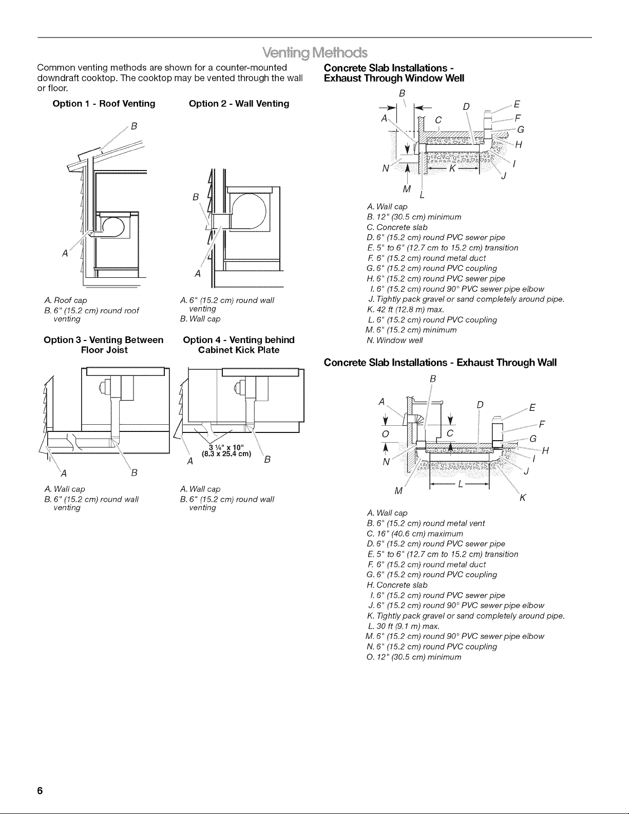
Common venting methods are shown fora counter-mounted Concrete Slab Installations -
downdraft cooktop. The cooktop may be vented through the wall Exhaust Through Window Well
or floor. B
Option 1 - Roof Venting Option 2 - Wall Venting
A. Wall cap
B. 12" (30.5 cm) minimum
C. Concrete slab
D. 6" (15.2 cm) round PVC sewer pipe
E. 5" to 6" (12.7 cm to 15.2 cm) transition
F. 6" (15.2 cm) round metal duct
G. 6" (15.2 cm) round PVC coupling
H. 6" (15.2 cm) round PVC sewer pipe
I. 6" (15.2 cm) round 90 ° PVC sewer pipe elbow
A. Roof cap
B. 6" (15.2 cm) round roof
venting
Option 3 - Venting Between
Floor Joist
A. 6" (15.2 cm) round wall
venting
B. Wall cap
Option 4 - Venting behind
Cabinet Kick Plate
Concrete
J. Tightly pack gravel or sand completely around pipe.
K. 42 ft (12.8 m) max.
L. 6" (15.2 cm) round PVC coupling
M. 6" (15.2 cm) minimum
N. Window well
Slab Installations - Exhaust Through Wall
B
L
L
L
l
L
'_A B
A. Wall cap
B. 6" (15.2 cm) round wall
venting
= " = "
A (8._'2II_m) B
A. Wall cap
B. 6" (15.2 cm) round wall
venting
A D
0
M
A. Wall cap
B. 6" (15.2 cm) round metal vent
C. 16" (40.6 cm) maximum
D. 6" (15.2 cm) round PVC sewer pipe
E. 5" to 6" (12.7 cm to 15.2 cm) transition
F. 6" (15.2 cm) round metal duct
G. 6" (15.2 cm) round PVC coupling
H. Concrete slab
I. 6" (15.2 cm) round PVC sewer pipe
J. 6" (15.2 cm) round 90 ° PVC sewer pipe elbow
K. Tightly pack gravel or sand completely around pipe.
L. 30 ft (9.1 m) max.
M. 6" (15.2 cm) round 90 ° PVC sewer pipe elbow
N. 6" (15.2 cm) round PVC coupling
O. 12" (30.5 cm) minimum
F
K
6
Page 7
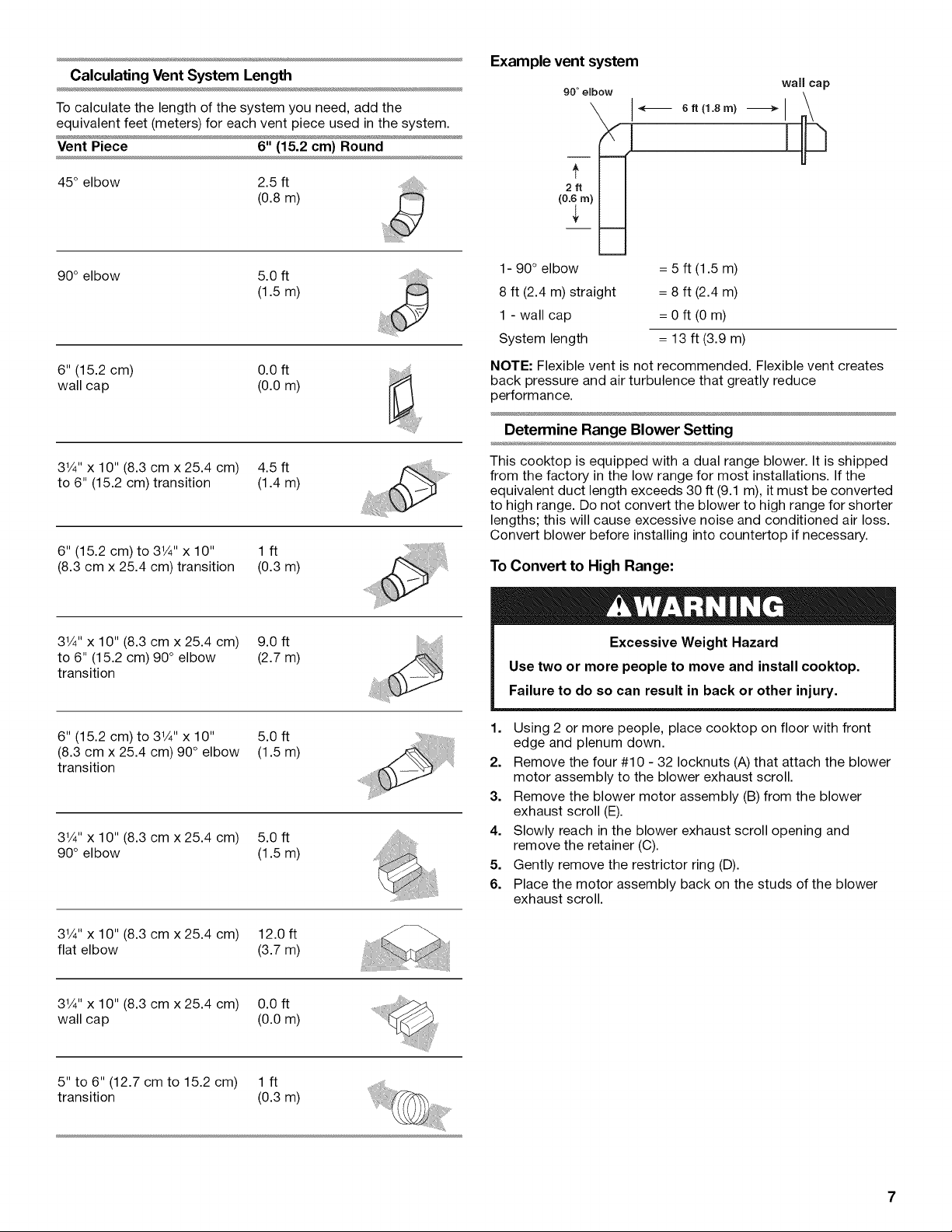
Calculating Vent System Length
To calculate the length of the system you need, add the
equivalent feet (meters) for each vent piece used in the system.
Vent Piece 6" (15.2 cm) Round
45° elbow 2.5 ft
(0.8m)
Example vent system
90 ° elbow
(
wall cap
I
90° elbow 5.0 ft
(1.5m)
6" (15.2 cm) 0.0 ft
wall cap (0.0 m)
31/4"x 10" (8.3 cm x 25.4 cm) 4.5 ft
to 6" (15.2 cm) transition (1.4 m)
6" (15.2 cm) to 31/4'' x 10" 1 ft
(8.3 cm x 25.4 cm) transition (0.3 m)
31/4"x 10" (8.3 cm x 25.4 cm) 9.0 ft
to 6" (15.2 cm) 90° elbow (2.7 m)
transition
1- 90 ° elbow = 5 ft (1.5 m)
8 ft (2.4 m) straight = 8 ft (2.4 m)
1 - wall cap = 0 ft (0 m)
System length = 13 ft (3.9 m)
NOTE: Flexible vent is not recommended. Flexible vent creates
back pressure and air turbulence that greatly reduce
performance.
Determine Range Blower Setting
This cooktop is equipped with a dual range blower. It is shipped
from the factory in the low range for most installations. If the
equivalent duct length exceeds 30 ft (9.1 m), it must be converted
to high range. Do not convert the blower to high range for shorter
lengths; this will cause excessive noise and conditioned air loss.
Convert blower before installing into countertop if necessary.
To Convert to High Range:
Excessive Weight Hazard
Use two or more people to move and install cooktop.
Failure to do so can result in back or other injury.
6" (15.2 cm) to 31/4'' x 10" 5.0 ft
(8.3 cm x 25.4 cm) 90 ° elbow (1.5 m)
transition
31/4"x 10" (8.3 cm x 25.4 cm) 5.0 ft
90° elbow (1.5 m)
31/4'' x 10" (8.3 cm x 25.4 cm) 12.0 ft
flat elbow (3.7 m)
31/4'' x 10" (8.3 cm x 25.4 cm) 0.0 ft
wall cap (0.0 m)
5" to 6" (12.7 cm to 15.2 cm) 1 ft
transition (0.3 m)
1. Using 2 or more people, place cooktop on floor with front
edge and plenum down.
2. Remove the four #10 - 32 Iocknuts (A)that attach the blower
motor assembly to the blower exhaust scroll.
3. Remove the blower motor assembly (B) from the blower
exhaust scroll (E).
4. Slowly reach in the blower exhaust scroll opening and
remove the retainer (C).
5. Gently remove the restrictor ring (D).
6. Place the motor assembly back on the studs of the blower
exhaust scroll.
Page 8
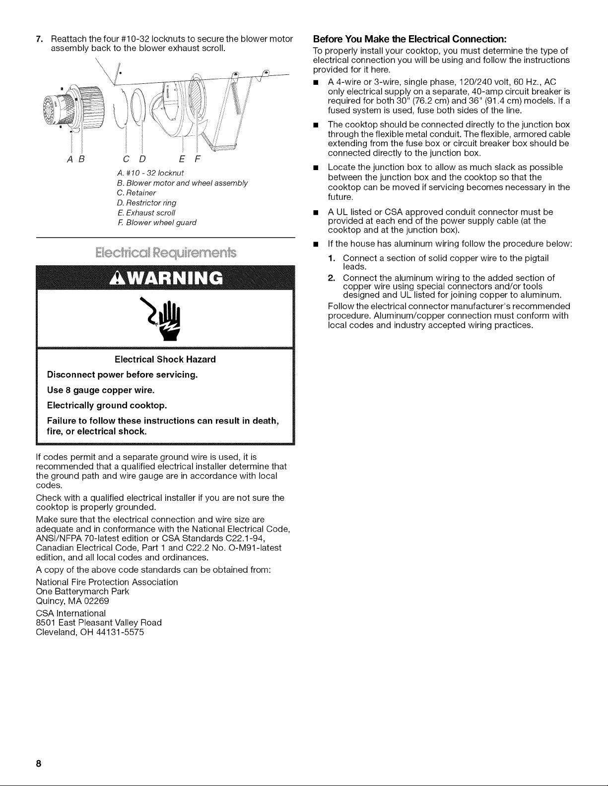
7. Reattachthefour#10-32Iocknutstosecuretheblowermotor
assemblybacktotheblowerexhaustscroll.
\
AB C D E F
A. #10 -32 Iocknut
B. Blower motor and wheel assembly
C. Retainer
D. Restrictor ring
E.Exhaust scrofl
F. Blower wheel guard
E ¸ _ _I_,_,_ I _E_I,,_ !i_£_
Before You Make the Electrical Connection:
To properly install your cooktop, you must determine the type of
electrical connection you will be using and follow the instructions
provided for it here.
• A 4-wire or 3-wire, single phase, 120/240 volt, 60 Hz., AC
only electrical supply on a separate, 40-amp circuit breaker is
required for both 30" (76.2 cm) and 36" (91.4 cm) models. If a
fused system is used, fuse both sides of the line.
The cooktop should be connected directly to the junction box
through the flexible metal conduit. The flexible, armored cable
extending from the fuse box or circuit breaker box should be
connected directly to the junction box.
Locate the junction box to allow as much slack as possible
between the junction box and the cooktop so that the
cooktop can be moved if servicing becomes necessary in the
future.
A UL listed or CSA approved conduit connector must be
provided at each end of the power supply cable (at the
cooktop and at the junction box).
• If the house has aluminum wiring follow the procedure below:
1. Connect a section of solid copper wire to the pigtail
leads.
2. Connect the aluminum wiring to the added section of
copper wire using special connectors and/or tools
designed and UL listed for joining copper to aluminum.
Follow the electrical connector manufacturer's recommended
procedure. Aluminum/copper connection must conform with
local codes and industry accepted wiring practices.
Electrical Shock Hazard
Disconnect power before servicing.
Use 8 gauge copper wire.
Electrically ground cooktop.
Failure to follow these instructions can result in death,
fire, or electrical shock.
If codes permit and a separate ground wire is used, it is
recommended that a qualified electrical installer determine that
the ground path and wire gauge are in accordance with local
codes.
Check with a qualified electrical installer if you are not sure the
cooktop is properly grounded.
Make sure that the electrical connection and wire size are
adequate and in conformance with the National Electrical Code,
ANSI/NFPA 70-latest edition or CSA Standards C22.1-94,
Canadian Electrical Code, Part 1 and C22.2 No. O-M91-1atest
edition, and all local codes and ordinances.
A copy of the above code standards can be obtained from:
National Fire Protection Association
One Batterymarch Park
Quincy, MA 02269
CSA International
8501 East Pleasant Valley Road
Cleveland, OH 44131-5575
8
Page 9

INSTALLATIONINSTRUCTIONS
Decide on the final location for the cooktop.
Excessive Weight Hazard
Use two or more people to move and install cooktop.
Failure to do so can result in back or other injury.
1. Open product as instructed on product packaging.
2. Remove shipping materials and tape from cooktop.
3. Remove vent grille.
Is: mSnp
1.
Remove foam strip from the package containing literature.
2.
Remove backing from foam strip.
3.
Apply foam strip adhesive-side down around bottom of
cooktop, flush with edge.
NOTE: The foam strip keeps the underside of the cooktop
glass free from debris and helps the cooktop sit flat on
uneven counters.
A. Cooktop base
B. Foam strip
C. Glass
C
(;I
IMPORTANT: The following additional steps must be performed
if the product is being installed in peninsula or island cabinetry.
The blower exhaust scroll is shipped from the factory set to
exhaust straight out the back of the cabinet through an exterior
wall.
D
A. Vent grifle
B. Plenum
C. Removable grease filter
D. Ceramic glass top
4. Remove the removable grease filter by lifting the filter out.
5. Using 2 or more people, remove the cooktop from the carton.
6. Use foam end caps from the packaging as a work surface for
the floor or countertop.
7. Using 2 or more people, place the cooktop upside down on
the foam end caps.
8. Make sure knobs are positioned in the open areas of the end
caps.
9. Avoid placing the cooktop facedown on the control knobs.
D
/
B
F
A.Blower exhaust scroll
B.Plenum
C.Blower motor
D.Toplabel
E. 10-32 machine nuts (4)
F.Motor mounting plate
Page 10

To rotate blower:
1. Locate the four plastic plugs in the plenum bypass.
2. Use the pliers to remove the plastic plugs.
IMPORTANT: Do not throw away the plastic plugs. The
plastic plugs must be reinstalled after the blower exhaust
scroll has been rotated.
To rotate blower motor:
NOTE: The "Top" label location on the blower motor is at the
9 o'clock position.
1. Using a ratchet with a 3/8"socket and supporting the motor
with one hand, remove the four machine nuts that attach the
blower motor to the exhaust scroll.
2. Remove the blower motor and wheel assembly from the weld
studs.
D
C
A. Blower motor
B. Exhaust scroll
C. Plenum
D. Plastic plugs (4)
3. Insert the 3/8"socket and extension into the hole and use the
ratchet handle to loosen the nut half of a rotation. Repeat this
process for each of the four nuts.
4. With the nuts loosened, the blower exhaust scroll can be
easily rotated downward.
D
A
C
A. Top label
B. Blower motor
C. Motor mounting plate
D. Weld stud location
E. Blower wheel
3. When the motor mounting plate clears the threaded weld
studs, rotate the assembly clockwise 90° and reinstall the
four #10-32 machine nuts.
4. Verify the "Top" label is positioned as shown.
5. Retighten each nut with the 3/8"socket, extension and ratchet.
6. Reinstall the four plastic plugs.
10
I
A. Top label
Page 11

_,_C_Co0 i£D©
1. Using 2 or more people, place cooktop right side up into the
cutout.
NOTE: Make sure that the front edge of the cooktop is
parallel to the front edge of the countertop. If repositioning is
needed, lift entire cooktop up from the cutout to avoid
scratching the countertop.
2. For island or peninsula installations, go to "Rotate Blower -
Optional" section.
3. Connect blower exhaust scroll to ducting.
4. Use vent clamps to secure the ducting to the blower exhaust
scroll.
5. Reinstall removable grease filter.
6. Reinstall vent grille.
Mc,, <®E Connect on
Electrical Shock Hazard
Disconnect power before servicing.
Use 8 gauge copper wire.
Electrically ground cooktop.
Failure to follow these instructions can result in death,
fire, or electrical shock.
Electrical Connection Options
If your home has: And you will be Go to Section:
connecting to:
4-wire A fused 4-Wire Cable from
disconnect or Power Supply
circuit breaker
box
3-wire A fused 3-Wire Cable from
disconnect or Power Supply
circuit breaker
box
4-Wire Cable from Home Power Supply to 4-Wire Cable
from Cooktop
IMPORTANT: Use the 4-wire cable from home power supply in
the U.S. where local codes do not allow grounding through
neutral, New Branch circuit installations (1996 NEC), mobile
homes and recreational vehicles, new construction, and in
Canada.
A
E
This cooktop is manufactured with the frame connected to the
bare ground wire. Connect the cooktop cable to the junction box
through the UL listed or CSA approved conduit connector.
1. Disconnect power.
2. Remove junction box cover, if present.
3. Connect the flexible cable conduit from the cooktop to the
junction box using a UL listed or CSA approved conduit
connector.
4. Tighten screws on conduit connector if present.
5. See "Electrical Connection Options Chart" to complete
installation for your type of electrical connection.
A. Cable from home power supply
B. Black wires
C. Bare ground wires
D. 4-wire cable from cooktop
E.Junction box
F. White wires
G. UL listed wire connector
H. Red wires
I. UL fisted or CSA approved
conduit connector
1. Connect the 2 black wires together using the UL listed wire
connectors.
2. Connect the 2 red wires together using the UL listed wire
connectors.
3. Connect the 2 white wires together using the UL listed wire
connectors.
4. Connect the green (or bare) ground wire from the cooktop
cable to the green (or bare) ground wire (in the junction box)
using the UL listed wire connectors.
5. Install junction box cover.
11
Page 12

3-WireCablefromHomePowerSupplyto4-WireCable
fromCooktop-U.S.only
IMPORTANT: Use the 3-wire cable from power supply where
local codes permit connecting the frame-ground conductor to
the neutral (white) junction box wire.
A
E
F
G
H
C
D
1. Check that all parts are now installed. If there is an extra part,
go back through the steps to see which step was skipped.
2. Check that you have all your tools.
3. Dispose of/recycle all packaging materials.
4. Use a mild solution of liquid household cleaner and warm
water to clean cooktop before use. Dry thoroughly with a soft
cloth. For more information, see the "Cooktop Care" section
of the Use and Care Guide.
5. Read "Cooktop Use" in the cooktop Use and Care Guide.
6. Reconnect power.
7. Use the Flow Tester Card provided with your cooktop to
check the airflow (see card for step-by-step instructions).
NOTE: If the cooktop does not work after turning on the power,
check that a circuit breaker has not tripped or a household fuse
has not blown. See "Troubleshooting" section in the Use and
Care Guide for further information.
A. Cable from home power supply
B. Red wires
C. White wire and green (or bare)
wire (from cooktop)
D. 4-wire cable from cooktop
E.Junction box
F. White wire
G. UL fisted wire connector
H. Black wires
I. UL listed or CSA approved
conduit connector
1. Connect the 2 black wires together using the UL listed wire
connectors.
2. Connect the 2 red wires together using the UL listed wire
connectors.
3. Connect the green or bare and white cooktop cable wires to
the white (neutral) wire in the junction box using the UL listed
wire connectors.
4. Install junction box cover.
If you need Assistance or Service:
Please reference the "Assistance or Service" section of the Use
and Care Guide or contact the dealer from whom you purchased
your cooktop.
12
Page 13

SECURITEDELATABLEDECUlSSON
Votre securite et celle des autres est tres importante.
Nous donnons de nombreux messages de s_curit_ importants dans ce manuel et sur votre appareil m_nager. Assurez-vous de
toujours lire tousles messages de s_curit_ et de vous y conformer.
Ce symbole d'alerte de s_curit_ vous signale les dangers potentiels de d_c_s et de blessures graves & vous
et & d'autres.
Voici le symbole d'alerte de s_curit&
Tousles messages de s_curit_ suivront le symbole d'alerte de s_curit_ et le mot "DANGER" ou
"AVERTISSEMENT". Ces mots signifient •
Risque possible de d_cbs ou de blessure grave si vous ne
suivez pas imm_diatement les instructions.
Risque possible de d_cbs ou de blessure grave si vous
ne suivez pas les instructions.
Tousles messages de s_curit_ vous diront quel est le danger potentiel et vous disent comment r_duire le risque de blessure et
ce qui peut se produire en cas de non-respect des instructions.
13
Page 14

EXIGENCESD'INSTALLATION
O fis ®tp
Rassembler les outils et pieces necessaires avant d'entreprendre
I'installation. Lire et suivre les instructions fournies avec chacun
des outils de la liste ci-dessous.
Outils n_cessaires
• Metre-ruban •
• Tournevis a lame plate •
• Tournevis cruciforme •
• Perceuse •
• Niveau •
• Rallonge pour cle a douille
de 6"
Pi_ces fournies
• Grille de ventilation
• Pre-filtre
Pi_ces n_cessaires
• Un collier de serrage (homologation UL ou CSA) pour alveole
defon£'able de 7/8"(2,2 cm).
• Un connecteur de conduit (homologation UL ou CSA) pour
conduit de taille commerciale (trade size) de 1/2"(1,3 cm) &
armature metallique
• Connecteurs de fils (homologation UL)
• Conduit metallique
• Bouche de decharge murale
Clapet de bouche de decharge murale & surface arrondie de
6" (15,2 cm)
Commander la piece numero A406
Clapet de bouche de decharge murale & surface arrondie de
5" (12,7 cm)
Commander la piece numero A405
Clapet de bouche de decharge murale & surface arrondie de
31¼"x 10" (8,3 x 25,4 cm)
Commander la piece numero A403
Pour commander, voir la section "Assistance ou service" du
Guide d'utilisation et d'entretien.
• Bride de conduit
Consulter les codes Iocaux. Verifier I'alimentation electrique
existante. Voir la section "Specifications electriques".
II est recommande de faire realiser tousles raccordements
electriques par un electricien qualifie agree.
IMPORTANT : Observer les dispositions de tousles codes et
reglements en vigueur. Lors de I'installation de la table de
cuisson, utiliser les dimensions minimales indiquees.
• Afin de supprimer le risque de brQlures ou d'incendie en se
penchant au-dessus des unites de surface chauffees, le
rangement en armoire au-dessus des unites de surface doit
_tre evite. Si des placards de rangement sont envisages, le
risque peut _tre reduit par I'installation d'une hotte de cuisine
depassant le bas des placards d'au moins 5" (12,7 cm)
horizontalement.
Marqueur ou crayon
Pince
Foret de 1¼,,
Scie sauteuse
Cle & cliquet avec douille de
3/8"
• Utiliser les dimensions d'ouverture du plan de travail qui sont
indiquees dans ces Instructions d'installation. Les
dimensions donnees sont les espacements minimaux et
fournissent un degagement de 0" (0 cm).
• Une source d'electricite avec liaison & la terre est necessaire.
Voir la section "Specifications electriques".
• Si le placard comporte des tiroirs, ces tiroirs doivent _tre
retires et I'avant des tiroirs installe sur I'avant du placard.
IMPORTANT • II n'est pas possible d'installer un four encastre
sous plan de travail sous ce produit.
Dimensions du produit
Table de cuisson de 30" (76,2 cm) - Pour les modules
standard et _lectriques
A
A. Emplacement/d_gagement du modele/de la plaque
signal_tique
B.21" (53,4 cm) d'une t#te de vis b I'autre
C. 22" (52,3 cm) sans garniture en acier inoxydable ou
21sz/e4"(54, 8 cm) avec garniture en acier inoxydable
B
E
1 .....................
F-*
_G_
A. 301/3_'' (76,3 cm) avec garniture en acier inoxydable
B. 29W_6" (76,1 cm) sans garniture en acier inoxydable
C. 14_/16'' (36,4 cm)
D. 3s½2" (10,1 cm)
E. 1813/32'' (46,8 cm)
F. 11½_'' (3,4 cm)
G. 13%2" (33,3 cm)
H. 14s/16'' (36,0 cm)
/. 28%" (72, 7 cm) d'une t#te de vis b I'autre
!_______C _._._._.____
6) _ @: ® @
i
I
14
Page 15

Table de cuisson de 36" (91,4 cm) - Pour les modules
standard et _lectriques
Dimensions du placard
C
A. Emplacement/d_gagement du modele/de la plaque signal_tique
B. 21" (53,4 cm) d'une t_te de vis _ I'autre
C. 22" (52,3 cm) sans garniture en acier inoxydable ou
2137/64"(54,8 cm) avec garniture en acier inoxydable
A
B
A. 35_%4" (90,1 cm) avec garniture en acier inoxydable
B.35_5/64'' (89,9 cm) sans garniture en acier inoxydable
C. 1731/64'' (43,8 cm)
D. 3_%_" (9,6 cm)
E. 1813/32''(46,8 cm)
F. 817/64 '' (20,9 cm)
G. 13s/3_'' (33,3 cm)
H. 131/16'' (33,2 cm)
I. 3431/64'' (87,6 cm) d'une t#te de vis _ I'autre
C
A. 30" (76,2 cm) sur les modeles de 30" (76,2 cm)
36" (91,4 cm) sur les modeles de 36" (91,4 cm)
B. Zone de matiere combustible au-dessus du plan de travail (espace
d_limit_ par des lignes pointill_es ci-dessus)
C. Distance minimale de s_paration de 30" (76,2 cm) entre le dessus
de la table de cuisson et le fond d'un placard m_tallique ou de bois
non couvert (distance de s_paration de 24" [61 cm] ou plus si le
fond du placard de m_tal ou de bois est recouvert d'une plaque
d'au moins 1/4"(0,6 cm) de mat_riau r_sistant aux flammes, lui-
m_me recouvert d'une feuille m_talfique d'une _paisseur
correspondant bun calibre de 28 au moins pour I'acier, 0,015"
[0,04 cm] pour I'acier inoxydable, 0,024" [0,06 cm] pour I'aluminium
ou 0,020" [0,05 cm] pour le cuivre)
D. Profondeur recommand_e pour les placards sup_rieurs : 13"
(33 cm)
E.2"(5,1 cm)
F. 211/8'' (73,4 cm)
G. Distance de s_paration minimale de 18" (45, 7 cm) entre le placard
sup_rieur et le plan de travail avec distance minimale de s_paration
horizontale pour la table de cuisson
H. Boftier de connexion ou prise _lectrique; 12" (30,5 cm) ou plus
depuis le bas du plan de travail
I. Boftier de connexion ou prise _lectrique; 10" (25,4 cm) depuis le
c6t_ droit du placard
J. 287/8" (73,4 cm) sur les modeles de 30" (76,2 cm)
349/16''(87,8 cm) sur les modeles de 36" (91,4 cm)
K. Distance de s_paration minimale de 2V2" (6,4 cm) par rapport _ la
surface de mat_riau combustible la plus proche, _ gauche ou
droite au-dessus de la table de cuisson
L. Distance de s_paration minimale de 1V2"(3,8 cm) ou plus entre la
paroi arriere et le plan de travail
REMARQUES •Apr_s le decoupage de I'ouverture dans le plan
de travail, il est possible que pour certaines configurations
d'installation, il soit necessaire d'entailler les parois laterales du
placard inferieur pour permettre le passage de la base de la table
de cuisson. Pour eviter cette modification, utiliser un placard
inferieur dont la largeur des parois laterales est superieure & celle
de I'ouverture decoupee.
• Un degagement minimum de 6" (15,2 cm) entre le c6te de la
table de cuisson et la paroi laterale est recommande pour une
performance maximale de ventilation.
• Un degagement minimum de 2" (5,1 cm) entre le moteur/
ventilateur et le placard est recommande pour que le
refroidissement puisse s'effectuer correctement. Un
degagement de 6" (15,2 cm) est recommande pour pouvoir
acceder en cas de reparation.
15
Page 16

Dimensions de I'ouverture _ d_couper
A B
H
A. 28%" (73,4 cm) maximum sur les modeles de 30" (76,2 cm)
34%6" (87,8 em) maximum sur les modeles de 36" (91,4 em)
B. 211/8'' (53, 7 em) maximum sur les modeles de 30" (76,2 em) et de
36" (91,4 cm)
C. 81%_'' (21,8 cm) sur les modeles de 30" (76,2 cm)
157/16''(39,2 cm) sur les modeles de 36" (91,4 cm)
D. 61%4'' (16,0 cm) sur les modeles de 30" (76,2 cm) et 36" (91,4 cm)
E. D_gagement minimal de 2" (5,1 cm) jusqu 'au rebord avant de la
table de cuisson
F. Option d'_vaeuation par le plancher
G. 61/6'' (15,6 cm) pour un systeme d'_vacuation de 6" (15,2 cm)
51/6'' (13 cm) pour un systeme d'_vacuation de 5" (12, 7 cm)
H. 81%_'' (21,8 em) sur les modeles de 30" (76,2 cm)
157/16''(39,2 cm) sur les modeles de 36" (91,4 cm)
I. 16" (40,6 cm) sur les modeles de 30" (76,2 cm) et de 36" (91,4 cm)
J. Option d'_vacuation par lemur
Exqj@:'_c®s co_/sc@mc_Js_ ® c_Jc_'/'o
IIIVIPORTANT : L'evacuation de cette table de cuisson doit se
faire a I'exterieur.
• Ne pas terminer le circuit d'evacuation dans un grenier ou
dans un autre espace ferme.
• Utiliser un clapet de conduit.
• Le systeme doit decharger I'air a I'exterieur.
• Utiliser uniquement du conduit metallique de 6" (15,2 cm) ou
un conduit d'evacuation rectangulaire de 31¼'' x 10" (8,3 x
25,4 cm), sauf dans les cas suivants : avec une cuisiniere
electrique, un conduit metallique rond de 5" (12,7 cm) peut
_tre utilise pour une evacuation directement depuis I'arriere
de la cuisiniere a travers lemur sur une Iongueur de 10 pi
(3,0 m) au maximum.
• Avant d'effectuer des decoupes, s'assurer qu'il y a un
degagement convenable entre lemur ou le plancher pour le
conduit d'evacuation.
• On ne doit couper un poteau de colombage ou une solive
que si c'est absolument necessaire. Dans ce cas, on devra
construire une structure de support appropriee.
• La taille du conduit doit _tre uniforme.
• Le circuit d'evacuation doit comporter un clapet. Si la bouche
de decharge murale ou par le toit comporte un clapet, ne pas
utiliser le clapet fourni avec la hotte de cuisiniere.
• Au niveau de chaque jointure du circuit d'evacuation, assurer
I'etancheite avec les brides de serrage.
• A I'aide d'un produit de calfeutrage, assurer I'etancheite
autour de la bouche de decharge a I'exterieur (&travers le
mur ou le toit).
• Determiner quelle methode d'evacuation est la plus
appropriee.
Pour obtenir la meilleure performance •
• Utiliser un conduit de ventilation en acier galvanise
d'epaisseur minimum n° 26 ou en aluminium d'epaisseur
minimum n° 25. Des raccords de mauvaise qualite peuvent
reduire le flux d'air. On deconseille I'emploi d'un conduit en
metal flexible.
REMARQUE • Les codes Iocaux pourraient exiger un
materiau plus epais.
• Le conduit metallique peut _tre reduit &une epaisseur
n° 30 pour I'acier galvanise ou n° 26 pour I'aluminium si c'est
permis par les codes Iocaux. Cette information est basee sur
I'information dans la Section des Codes Residentiels
Internationaux M1601.1 (edition 2006).
• Ne pas installer 2 coudes ensemble.
• Ne pas utiliser plus de trois coudes & 90°.
• Si I'on utilise un coude, on doit le placer le plus loin possible
de I'ouverture d'evacuation du moteur de la hotte de
ventilation.
• Veiller & incorporer une section de conduit rectiligne d'au
moins 18" (45,7 cm) entre deux raccords coudes adjacents.
• Des coudes trop rapproches peuvent occasionner une
turbulence excessive qui reduirait la circulation de I'air.
• Ne pas utiliser un coude de 5" (12,7 cm) dans un systeme de
6" (15,2 cm) ou 3V4" x 10" (8,3 x 25,4 cm).
• Ne pas reduire lesysteme &une Iongueur de 5" (12,7 cm)
apres avoir utilise des raccords de 6" (15,2 cm) ou de 3V4" x
10" (8,3 x 25,4 cm).
• €:viter le sertissage manuel. Ceux-ci peuvent restreindre le
flux d'air.
• Utiliser un clapet de conduit pour que le rendement soit
correct. Si une bouche de decharge murale ou de toit est
utilisee, s'assurer que la taille de la bouche de decharge n'est
pas reduite et qu'il a un clapet anti-reflux.
• Au niveau de chaque jointure du circuit d'evacuation, assurer
I'etancheite avec les brides de serrage.
• A I'aide d'un produit de calfeutrage, assurer I'etancheite
autour de la bouche de decharge a I'exterieur (&travers le
mur ou le toit).
La Iongueur du systeme d'evacuation et le nombre de coudes
doit _tre reduit au minimum pour une performance efficace.
La Iongueur maximale equivalente du circuit d'evacuation est de
60 pi (18,3 m). Pour les altitudes excedant 4 500 pi (1272 m),
reduire la Iongueur du systeme d'evacuation de 20 % pour une
performance optimale.
16
Page 17

Installations pour r_gions a climat froid
On devrait installer un clapet anti-reflux additionnel pour
minimiser le reflux d'air froid, et incorporer un el6ment d'isolation
thermique pour minimiser la conduction de chaleur par
I'intermediaire du conduit d'evacuation, de I'interieur de la
maison & I'exterieur. Le clapet anti-reflux doit _tre place du c6te
air froid par rapport & I'el6ment d'isolation thermique.
Air d'appoint
Le code du b&timent local peut exiger I'emploi d'un systeme de
renouvellement de Fair/introduction d'air d'appoint, Iors de
I'utilisation d'un systeme d'aspiration de debit superieur &une
valeur (pieds cubes par minute) specifi6e. Le debit specifi6 en
pieds cubes par minute varie d'une juridiction & I'autre. Consulter
un professionnel des installations de chauffage/ventilation/
climatisation au sujet des exigences specifiques applicables
clans la juridiction locale.
Les methodes d'evacuation standard illustrees correspondent &
une table de cuisson avec aspiration par le bas montee sur
comptoir. L'evacuation de la table de cuisson peut se faire par le
mur ou le plancher.
Option 1 - D_charge a Option 2 - D_charge
travers le toit travers le tour
....//g
Installationsdansdalledeb_ton - I_vacuationa & travers un
puits de fen_tre
B
A. Bouche de d_charge murale
B. 12" (30,5 cm) minimum
C. Dalle de b_ton
D. Conduit PVC pour _gout de dia. 6" (15,2 cm)
E. Raccord de transition de 5" _ 6" (12, 7cm _ 15,2 cm)
F. Conduit m_tallique de dia. 6" (15,2 cm)
G. Raccord PVC de dia. 6" (15,2 cm)
H. Conduit PVC pour _gout de dia. 6" (15,2 cm)
I. Coude _ 90 ° en PVC pour _gout de dia. 6" (15,2 cm)
J. Gravier ou sable compact_ tout autour du tuyau.
K. 42 pi (12,8 m) max.
L. Raccord PVC de dia. 6" (15,2 cm)
M. 6" (15,2 cm) minimum
N. Puits de fen_tre
A. Bouche de d_charge sur toit
B. Conduit de dia. 6" (15,2 cm)
pour sortie _ travers le toit
Option 3 - levacuation entre
les solives au plancher
x
\
B
A. Conduit de dia. 6" (15,2 cm)
pour sortie _ travers lemur
B. Bouche de d_charge murale
Option 4 - levacuation
derriere le garde-pieds de
la caisse
== ==
Installations dans dalle de b_ton - I_vacuation & travers le
mur
B
A. Bouche de d_charge murale
B. Conduit m_tallique de dia. 6" (15,2 cm)
C. 16" (40,6 cm) maximum
D. Conduit PVC pour _gout de dia. 6" (15,2 cm)
E. Raccord de transition de 5" _ 6" (12, 7cm _ 15,2 cm)
F. Conduit m_tallique de dia. 6" (15,2 cm)
G. Raccord PVC de dia. 6" (15,2 cm)
H. Dalle de b_ton
I. Conduit PVC pour _gout de dia. 6" (15,2 cm)
J. Coude _ 90 ° en PVC pour _gout de dia. 6" (15,2 cm)
K. Gravier ou sable compact_ tout autour du tuyau.
L. 30 pi (9,1 m) max.
M. Coude _ 90 ° en PVC pour _gout de dia. 6" (15,2 cm)
N. Raccord PVC de dia. 6" (15,2 cm)
O. 12" (30,5 cm) minimum
A. Bouche de d_charge murale
B. Conduit de dia. 6" (15,2 cm)
pour sortie _ travers lemur
A. Bouche de d_charge murale
B. Conduit de dia. 6" (15,2 cm)
pour sortie _ travers le mur
17
Page 18

Calcul de la Iongueur effective du circuit d'_vacuation
Pour calculer la Iongueur effective du circuit d'evacuation
necessaire, additionner les Iongueurs equivalentes (pieds/metres)
de tousles composants utilises dans le systeme.
Composant Conduit de diam_tre de 6"
(15,2 cm)
Coude a 45 ° 2,5 pi (0,8 m)
Exemple de circuit d'_vacuation
bouche de d_charge rnurale
c°udea90° _ 6pi(1,Sm) ----------__
Coude & 90 ° 5 pi (1,5 m)
Bouche de decharge murale de 0 pi (0 m)
6" (15,2 cm)
Raccord de transition de 31/4"x 4,5 pi (1,4 m)
10" (8,3 cm x 25,4 cm)
sur 6" (15,2 cm)
Raccord de transition de 6"
(15,2 cm) a 31/4'' x 10"
(8,3 cm x 25,4 cm)
Coude de transition &90° de 9 pi (2,7 m)
31/4'' x 10" (8,3 cm x 25,4 cm)
6" (15,2 cm)
Raccord coude a 90° de 6" 5 pi (1,5 m)
(15,2 cm) a 31/4'' x 10" (8,3 cm x
25,4 cm)
1 pi (0,3 m)
1 - coude a 90 °
section droite de 8 pi (2,4 m)
1 - bouche de decharge murale
Longueur totale
REMARQUE : On deconseille I'emploi d'un conduit flexible. Un
conduit flexible peut causer une retro-pression et des
turbulences de I'air, ce qui reduit considerablement la
performance.
D6terminer le r6glage du ventilateur de la cuisini_re
Cette table de cuisson est equip6e d'un ventilateur & deux debits.
Cet appareil est expedi6 & la configuration la plus basse, qui
convient & la plupart des installations. Si la Iongueur de conduit
equivalente depasse 30 pi (9,1 m), le ventilateur d'aspiration dolt
_tre converti au mode & forte aspiration. Ne pas convertir le
ventilateur d'aspiration au mode &forte aspiration pour une
courte duree ;cela entrainera un bruit excessif et une perte d'air
conditionn& Convertir le ventilateur d'aspiration avant de
I'installer sur le plan de travail, si necessaire.
= 5 pi (1,5 m)
= 8 pi (2,4 m)
= 0 pi (0,0 m)
= 13 pi (3,9 m)
Conversion au mode _ forte aspiration :
Risque du poids excessif
Utiliser deux ou plus de personnes pour d_placer et
installer la table de cuisson.
Le non=respect de cette instruction peut causer
une blessure au dos ou d'autre blessure.
Coude & 90 ° de
31/4"x 10" (8,3 cm x 25,4 cm) 5 pi (1,5 m)
Coude plat de
31/4"x 10" (8,3 cm x 25,4 cm) 12 pi (3,7 m)
Bouche de decharge murale
31/4'' x 10" (8,3 cm x 25,4 cm) 0 pi (0,0 m)
Raccord de transition de 5" & 1 pi
6" (12,7 cm & 15,2 cm) (0,3 m)
18
1. A I'aide de 2 personnes ou plus, placer la table de cuisson
sur le plancher avec le rebord avant et le plenum face vers le
bas.
2. Retirer les 4 contre-ecrous n°10-32 (A) qui fixent le moteur du
ventilateur & la spirale d'echappement du ventilateur
d'aspiration.
3. Retirer le moteur du ventilateur (B) de la spirale
d'echappement du ventilateur d'aspiration (E).
4. Atteindre lentement I'ouverture de la spirale d'echappement
du ventilateur d'aspiration et retirer le dispositif de retenue
(C).
5. Retirer doucement I'anneau d'etanch6it6 (D).
6. Reinstaller le moteur du ventilateur sur les goujons de la
spirale d'echappement du ventilateur d'aspiration.
Page 19

7. Reassembler les 4 contre-ecrous n°10-32 pour fixer le moteur
du ventilateur & la spirale d'echappement du ventilateur
d'aspiration.
AB C D E _-
A. Contre-_crous n° 10-32
B. Ensemble moteur-roue
C. Dispositif de retenue
D. Anneau d'_taneh_it_
E.Spirale d'_chappement
F. Garde-roue du ventilateur d'aspiration
Risque de choc _lectrique
D_connecter la source de courant _lectrique avant
rentretien.
Utiliser du fil en cuivre de calibre 8.
Relier la table de cuisson a la terre.
Le non-respect de ces instructions peut causer un
d_ces, un incendie ou un choc _lectrique.
Si on utilise un conducteur distinct de liaison &la terre Iorsque les
codes le permettent, il est recommande qu'un electricien qualifie
verifie que la liaison & la terre et le calibre du conducteur sont
conformes aux codes Iocaux.
Verifier avec un electricien qualifie si vous avez des doutes quant
&la qualite de la liaison &la terre de la table de cuisson.
S'assurer que la connexion electrique et le calibre des fils sont
appropries et conformes au National Electrical Code, &la norme
ANSI/NFPA 70 - derniere edition, ou & la norme CSA C22.1-94,
au Code canadien de I'electricit6, Partie 1 et C22.2 N° O-M91 -
derniere edition, et &tousles codes et r_glements Iocaux.
Pour obtenir un exemplaire des normes et codes ci-dessus,
contacter :
National Fire Protection Association
One Batterymarch Park
Quincy, MA 02269
CSA International
8501 East Pleasant Valley Road
Cleveland, OH 44131-5575
Avant d'_tablir la connexion _lectrique :
Pour installer la table de cuisson correctement, il faut etablir le
type de raccords electriques que I'on utilisera et suivre les
instructions indiqu6es ici.
• L'appareil doit _tre alimente uniquement par un circuit
monophase enCA uniquement de 120/240 Vet 60 Hz, &4 ills
ou 3 ills, sur un circuit s6pare de 40 amperes (pour les
modeles de 36" [91,4 cm] et les modeles de 30" [76,2 cm]). Si
I'on utilise un circuit proteg6 par fusible, il doit I'_tre a chaque
extremit6 du circuit.
La table de cuisson doit _tre connectee directement au
boitier de connexion par I'intermediaire du conduit metallique
flexible. Le c&ble blinde flexible sortant du boitier de
distribution (fusible ou disjoncteur) doit _tre raccorde
directement au boitier de connexion.
Placer le boitier de connexion pour laisser le plus de jeu
possible entre celui-ci et la table de cuisson pour pouvoir
deplacer la table de cuisson en cas de besoin de reparation &
I'avenir.
• Un connecteur de conduit homologue UL ou CSA doit _tre
fourni & chaque extremite du c&ble d'alimentation electrique
(& la table de cuisson et au boitier de connexion).
• Si le domicile est equipe d'un c&blage en aluminium, suivre
les instructions suivantes :
1. Raccorder une section de c&ble en cuivre massif aux
epissures flexibles.
2. Connecter le c&blage en aluminium & la section ajoutee
de c&blage en cuivre en utilisant des connecteurs et/ou
des outils specialement congus et homologu_s UL pour
fixer le cuivre &I'aluminium.
Suivre la procedure recommandee par le fabricant de
connecteurs electriques. La connexion aluminium/cuivre doit
_tre conforme aux codes Iocaux et aux pratiques de c&blage
acceptees par I'industrie.
19
Page 20

INSTRUCTIONSD'INSTALLATION
Determiner I'emplacement final de la table de cuisson.
Risque du poJds excessif
UtiJiser deux ou plus de personnes pour d_placer et
instaJJer Jatable de cuisson.
Le non=respect de cette instruction peut causer
une blessure au dos ou d'autre blessure.
1. Ouvrir la boite tel que stipule sur I'emballage du produit.
2. Enlever les materiaux d'expedition et le ruban adhesif de la
table de cuisson.
3. Retirer la grille de ventilation.
A
C
D
n de ne e mo x
1,
Enlever la bande de mousse du sachet de documentation.
2.
Retirer I'endos de la bande de mousse.
3.
Appliquer le cSte adhesif de la bande de mousse autour du
fond de latable de cuisson, en affleurement avec le rebord.
REMARQUE : La bande de mousse protege la face inferieure
du verre de la table de cuisson de tout residu et permet & la
table de cuisson de reposer a plat sur des plans de travail
irreguliers.
A. Base de la table de cuisson
B. Bande de mousse
C. Verre
ton du nt cuk2ve
IMPORTANT : Les etapes supplementaires suivantes doivent
@treexecut6es si le produit est installe dans une configuration
d'eb6nisterie en peninsule ou en ilot.
Au deballage, la spirale d'echappement du ventilateur est
orientee vers I'arriere du placard, pour une evacuation & travers
une paroi exterieure.
A. Grille de ventilation
B.Plenum
C. Filtre _ graisse amovible
D. Surface en vitroc_ramique
4. Retirer le filtre & graisse amovible en le soulevant.
5. A I'aide d'au moins 2 personnes, retirer la table de cuisson du
carton.
6. Utiliser les capuchons en mousse aux extremit6s de
I'emballage comme surface de travail pour le plancher et le
plan de travail.
7. A I'aide d'au moins deux personnes, placer la table de
cuisson & I'envers sur les capuchons en mousse des
extremit6s.
8. S'assurer que les boutons sont places dans les zones
ouvertes des capuchons des extremit6s.
9. €:viter de placer la table de cuisson avec la partie superieure
sur les boutons de commande.
o c
D
"A \ B
F
A. Volute d'_vacuation du ventilateur
B. Plenum
C. Moteur du ventilateur
D. E-tiquette indiquant le haut (Top)
E.E-crous m_caniques 10-32 (qt_ 4)
F. Platine de montage du moteur
20
Page 21

Pour tourner le ventilateur :
1. Reperer les 4 bouchons en plastique dans la derivation de la
chambre de distribution.
2. Les enlever a I'aide d'une pince.
IMPORTANT • Ne pas jeter les bouchons en plastique. Les
bouchons en plastique doivent 6tre reinstall6s une fois la
spirale d'echappement du ventilateur tournee.
C
A. Moteur du ventilateur
B. Spirale d'6chappement
C. PI6num
D. Bouchons en plastique (4)
3. Inserer la cle & douille de 3/8"et la rallonge dans le trou et
devisser recrou d'un demi-tour &raide de la poignee &
cliquet. Rep6ter cette operation pour chacun des quatre
ecrous.
4. Une fois les ecrous desserres, la spirale d'echappement du
ventilateur s'oriente sans effort vers le bas.
Pour tourner le moteur du ventilateur :
REMARQUE :L'etiquette indiquant le dessus "top" du moteur de
ventilateur se trouve a la position de 9 heures.
1. Tout en soutenant le moteur d'une main, utiliser une cle &
cliquet equip6e d'une douille de 3/8"pour retirer les quatre
ecrous &metaux fixant le moteur de ventilateur a la volute
d'evacuation.
2. Degager I'ensemble moteur-roue des goujons soudes.
D
A
C
A. Etiquette indiquant le haut (Top)
B. Moteur du ventilateur
C. Platine de montage du moteur
D. Emplacement des goujons soud6s
E. Roue du ventilateur
3. Lorsque la platine de montage du moteur est degag6e des
goujons soudes filetes, faire pivoter I'assemblage dans le
sens horaire de 90° et reinstaller les quatre boulons usines
n° 10-32.
4. Verifier que I'etiquette "Top" (dessus) est placee comme
illustre.
5. Resserrer chaque ecrou & raide de la cle & cliquet & douille
de 3/8".
6. Reinstaller les 4 bouchons d'obturation en plastique.
I
A. Etiquette indiquant le haut (Top)
21
Page 22

1= A l'aide d'au moins 2 personnes, placer la table de cuisson
dans l'ouverture en orientant la bonne surface vers le haut.
REMARQIE : S'assurer que le bord avant de la table de
cuisson est parallele au bord avant du plan de travail. S'il est
necessaire de repositionner la table de cuisson, la soulever
entierement de I'ouverture pour eviter de rayer le plan de
travail.
2. Pour des installations en lot ou en peninsule, passer a la
section "Rotation du ventilateur - Facultative".
3. Connecter la volute d'evacuation du ventilateur aux conduits.
4. Utiliser des brides de conduit pour fixer les conduits a la
volute d'evacuation du ventilateur.
5. Reinstaller le filtre a graisse amovible.
6. Reinstaller la grille de ventilation.
Risque de choc _lectrique
D_connecter la source de courant _lectrique avant
rentretien.
Utiliser du fil en cuivre de calibre 8.
Relier la table de cuisson a la terre.
Le non-respect de ces instructions peut causer un
d_cbs, un incendie ou un choc _lectrique.
Options de raccordement _lectrique
C&blage de la maison : Point de Voir la section
distribution : suivante :
4 conducteurs BoRe de C&ble &
disjoncteur ou 4 conducteurs
coupe-circuit depuis le point
avec fusible de distribution
3 conducteurs BoRe de C&ble &
disjoncteur ou 3 conducteurs
coupe-circuit depuis le point
avec fusible de distribution
C&ble & 4 conducteurs depuis le point de distribution du
domicile jusqu'au c&ble & 4 conducteurs de la table de
cuisson
IMPORTANT : Utiliser le c&ble & 4 conducteurs provenant du
point de distribution du domicile aux 12tats-Unis Iorsque les
codes ne permettent pas la mise & la terre par I'intermediaire du
conducteur neutre, en cas de nouvelle installation avec
alimentation par un circuit secondaire (1996 NEC), dans les
residences mobiles et les vehicules recr6atifs, dans les nouvelles
constructions et au Canada.
Un conducteur nu de liaison & la terre est connecte au chassis de
la table de cuisson Iors de la fabrication. Raccorder le cable de la
table de cuisson au boiler de connexion a I'aide du connecteur
de conduit homologu6 UL ou CSA.
1. Deconnecter la source de courant electrique.
2. Enlever le couvercle du boiler de connexion, le cas ech6ant.
3. Avec un connecteur de conduit (homologation UL ou CSA),
connecter le conduit de cable flexible de la table de cuisson
au boiler de connexion.
4. Serrer les vis du connecteur de conduit, le cas ech6ant.
5. Voir le "Tableau des options de raccordement electrique"
pour terminer I'installation correspondant a votre type de
raccordement electrique.
C
D
A. C#ble d'alimentation du
domicile
B. Conducteurs noirs
C. Conducteurs nus de liaison
la terre
D. C#ble _ 4 conducteurs depuis
la table de cuisson
E. Boftier de connexion
F. Conducteurs blancs
G. Connecteur de ills
(homologation UL)
H. Conducteurs rouges
I. Connecteur de conduit
(homologation UL ou CSA)
H
!
1. Connecter ensemble les 2 conducteurs noirs avec un
connecteur de fils (homologation UL).
2. Connecter ensemble les 2 conducteurs rouges avec un
connecteur de fils (homologation UL).
3. Connecter ensemble les 2 conducteurs blancs avec un
connecteur de fils (homologation UL).
4. Connecter le conducteur vert (ou nu) de liaison a la terre du
cable de la table de cuisson au conducteur vert (ou nu) de
liaison a la terre dans le boiler de connexion - utiliser un
connecteur de fils (homologation UL).
5. Reinstaller le couvercle du boiler de connexion.
22
Page 23

C&ble&3 conducteurs depuis le point de distribution du
domicile jusqu'au c&ble & 4 conducteurs de la table de
cuisson - E.-U. seulement
IMPORTANT : Utiliser le c&ble & 3 conducteurs depuis le point
de distribution Iorsque le code local en vigueur permet le
raccordement entre le conducteur de liaison & la terre du ch&ssis
et le conducteur neutre (blanc) clans le boitier de connexion.
A
C
D
A. C_ble d'alimentation
B. Conducteurs rouges
C. Conducteur blanc et nu ou vert
de liaison _ la terre (depuis la
table de cuisson)
D. C_ble _ 4 conducteurs depuis
la table de cuisson
E.BoTtler de connexion
F. Conducteur blanc
G. Connecteur de ills
(homologation UL)
H. Conducteurs noirs
I. Connecteur de conduit
(homologation UL ou CSA)
1. Connecter ensemble les 2 conducteurs noirs avec un
connecteur de fils (homologation UL).
2. Connecter ensemble les 2 conducteurs rouges avec un
connecteur de fils (homologation UL).
3. Connecter le conducteur vert ou nu et le conducteur blanc de
la table de cuisson au conducteur blanc (neutre) dans le
boitier de connexion avec un connecteur de fil
(homologation UL).
4. Reinstaller le couvercle du boitier de connexion.
E
F
G
H
Ach®v® 7 ns @on
1. Verifier que toutes les pieces sont maintenant installees. S'il
reste une piece, passer en revue les differentes etapes pour
decouvrir laquelle aurait et6 oubliee.
2. Verifier la presence de tousles outils.
3. Jeter/recycler tous les materiaux d'emballage.
4. Utiliser une solution d'eau tiede et de nettoyant menager
liquide doux pour nettoyer la table de cuisson avant
utilisation. Secher parfaitement avec un linge doux. Pour plus
de renseignements, voir la section "Entretien de la table de
cuisson" du Guide d'utilisation et d'entretien.
5. Lire "Utilisation de la table de cuisson" dans le Guide
d'utilisation et d'entretien de la table de cuisson.
6. Reconnecter la source de courant electrique.
7. Utiliser la carte de test du flux d'air fournie avec la table de
cuisson pour verifier le flux d'air (voir la carte pour des
instructions etape par etape).
REMARQUE : Si la table de cuisson ne fonctionne pas une fois
I'alimentation branchee, verifier que le disjoncteur n'est pas
declench6 ou que les fusibles ne sont pas grilles. Voir la section
"Depannage" dans le Guide d'utilisation et d'entretien pour plus
de renseignements.
Si vous avez besoin d'assistance ou de service :
Consulter la section "Assistance ou service" du Guide
d'utilisation et d'entretien ou contacter le marchand chez qui
vous avez achete votre table de cuisson.
23
Page 24

W10298568A
@2010.
All rights reserved.
Tous droits reserves.
Printed in U.S.A.
Imprime aux E.-U.
2/10
 Loading...