


KitchenAid KECD866RBL05, GJD3044RB03, GJD3044RB04, KECD866RWW04, KECD866RSS04 Installation Guide
...
30" (76.2CM) AND 36" (91.4CM)
ELECTRIC BUILT-IN CERAMIC DOWNDRAFT COOKTOP
INSTALLATION INSTRUCTIONS
INSTRUCTIONS D'INSTALLATIONDE
LA TABLEDE CUISSON ELECTRIQUEENCASTRI_EEN
CI_RAMIQUEA ASPIRATIONVERS LE BAS
DE 30"(76_ CM) ET36"(91,4CM)
Table of Contents
COOKTOP SAFETY ........................................................................ 1
INSTALLATION INSTRUCTIONS .................................................. 2
Tools and Parts ............................................................................ 2
Location Requirements ................................................................ 2
Venting Requirements .................................................................. 3
Plan Vent System ......................................................................... 4
Electrical Requirements ............................................................... 6
Unpack Cooktop .......................................................................... 7
Install Cooktop ............................................................................. 7
Install Vent System ....................................................................... 7
Make Electrical Connection ......................................................... 7
Complete Installation ................................................................... 8
SECURITI_ DE LA TABLE DE CUISSON ...................................... 9
INSTRUCTIONS D'INSTALLATION ............................................... 9
Outillage et pieces ........................................................................ 9
Exigences d'emplacement ........................................................... 9
Exigences concernant 1'6vacuation ........................................... 11
Planification du systeme d'6vacuation ...................................... 12
Sp6cifications electriques .......................................................... 14
D6ballage de la table de cuisson ............................................... 14
Installation de la table de cuisson .............................................. 14
Installation du conduit d'evacuation .......................................... 15
Raccordement 61ectrique ........................................................... 15
Achever I'installation .................................................................. 16
Table des mati(_res
COOKTOP SAFETY
Your safety and the safety of others are very important.
We have provided many important safety messages in this manual and on your appliance. Always read and obey all safety
messages.
This is the safety alert symbol.
This symbol alerts you to potential hazards that can kill or hurt you and others.
All safety messages will follow the safety alert symbol and either the word "DANGER" or "WARNING."
These words mean:
You can be killed or seriously injured if you don't immediately/
follow instructions,
You can be killed or seriously injured if you don't follow
instructions,
All safety messages will tell you what the potential hazard is, tell you how to reduce the chance of injury, and tell you what can
happen if the instructions are not followed.
IMPORTANT:
Installer: Leave installation instructions with the homeowner.
Homeowner: Keep installation instructions for future reference.
Save installation instructions for local electrical inspector's use.
IMPORTANT :
Installateur : Remettre les instructions d'installation au proprietaire,
Propri_taire : Conserver les instructions d'installation pour reference ulterieure.
Conserver les instructions d'installation pour consultation par I'inspecteur local des installations electriques.
8286240
INSTALLATIONINSTRUCTIONS
Gather the required tools and parts before starting installation.
Tools needed
• Tape measure • Pliers
• Phillips screwdriver • Metal snips
• Hand or electric drill • Caulking gun with
• Duct tape weatherproof caulking
Parts needed
• A UL listed or CSA approved conduit connector
• UL listed wire nuts
• Metal vent
• Wall or roof cap
Parts supplied
• Ventcover
Check local codes. Check existing electrical supply. See
"Electrical Requirements."
All electrical connections should be made by a licensed, qualified
electrical installer.
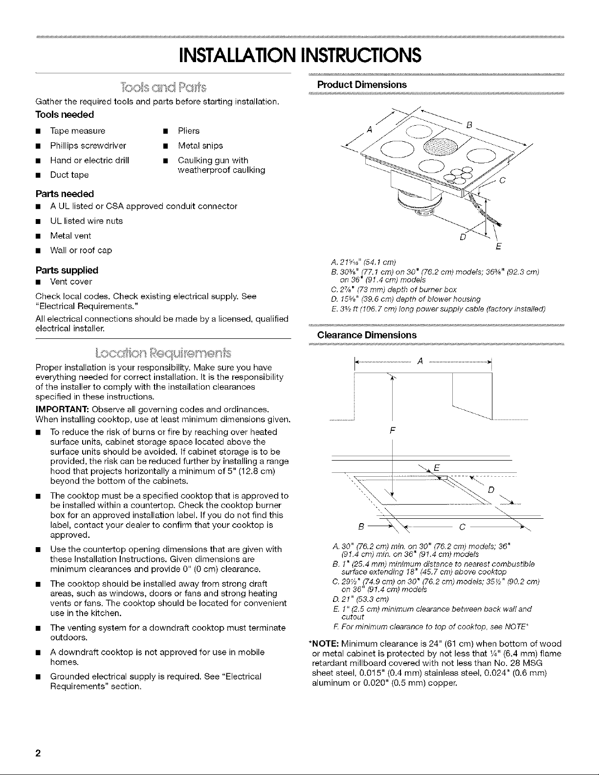
Product Dimensions
A
B
C
D
E
A. 21%6" (54.1 cm)
B. 303/_" (77.1 cm) on 30" (76.2 cm) models; 36%" (92.3 cm)
on 36" (91.4 cm) models
C. 27_" (73 ram) depth of bumer box
D. 15%" (39.6 cm) depth of blower housing
E. 3_/2ft (t06. 7 era) long power supply cable (factory installed)
Clearance Dimensions
Proper installation is your responsibility. Make sure you have
everything needed for correct installation. It is the responsibility
of the installer to comply with the installation clearances
specified in these instructions.
IMPORTANT: Observe all governing codes and ordinances.
When installing cooktop, use at least minimum dimensions given.
• To reduce the risk of burns or fire by reaching over heated
surface units, cabinet storage space located above the
surface units should be avoided. If cabinet storage is to be
provided, the risk can be reduced further by installing a range
hood that projects horizontally a minimum of 5" (12.8 cm)
beyond the bottom of the cabinets.
• The cooktop must be a specified cooktop that is approved to
be installed within a countertop. Check the cooktop burner
box for an approved installation label. If you do not find this
label, contact your dealer to confirm that your cooktop is
approved.
• Use the countertop opening dimensions that are given with
these Installation Instructions. Given dimensions are
minimum clearances and provide 0" (0 cm) clearance.
• The cooktop should be installed away from strong draft
areas, such as windows, doors or fans and strong heating
vents or fans. The cooktop should be located for convenient
use in the kitchen.
• The venting system for a downdraft cooktop must terminate
outdoors.
• A downdraft cooktop is not approved for use in mobile
homes.
• Grounded electrical supply is required. See "Electrical
Requirements" section.
................... A
F
B C _-..
A. 30" (76.2 cm) min. on 30" (76.2 cm) models; 36"
(91.4 cm) rain. on 36" (91.4 cm) models
B. 1" (25.4 ram) minimum distance to nearest combustible
surface extending 18" (45. 7 cm) above cooktop
C. 29V_" (74.9 cm) on 30" (76.2 cm) models; 36_/2" (90.2 cm)
on 36"(91.4 cm) models
D. 2t" (53.3 cm)
E. 1" (2.5 cm) minimum clearance between back wall and
cutout
F For minimum clearance to top of cooktop, see NOTE*
*NOTE: Minimum clearance is 24" (61 cm) when bottom of wood
or metal cabinet is protected by not less that 1/4"(6.4 ram) flame
retardant millboard covered with not less than No. 28 MSG
sheet steel, 0.015" (0.4 mm) stainless steel, 0.024" (0.6 ram)
aluminum or 0.020" (0.5 ram) copper.
2
Minimum clearance is 30" (76.2 cm) between bottom of
unprotected wood or sheet metal and the top of your cooking
platform.
If installing a hood above the cooktop, follow the hood
instructions for dimensional clearances above the cooktop
surface.
Side clearance: 6" (15.2 cm) minimum clearance between side of
cooktop and side wall is recommended for maximum ventilation
performance.
Rear clearance: %" (19.1 mm) clearance between rear edge of
cooktop and rear wall is recommended.
Motor/blower clearance: 2" (51 mm)minimum clearance between
motor and cabinet is required for proper cooling. A 6" (15.2 cm)
clearance is recommended for servicing access.
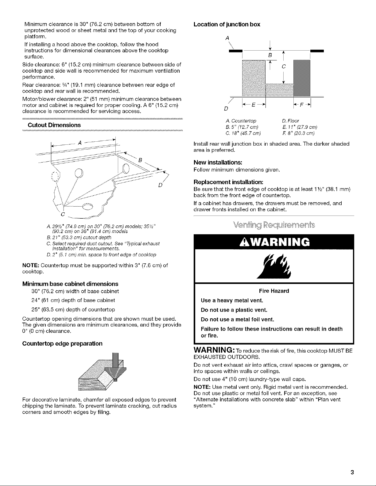
Cutout Dimensions
/
D
€
Location ofjuncSon box
A
B l
D
A. Countertop D. Floor
B. 5" (12.7cm) E. 11" (27.9cm)
C. 18" (45.7cm) F 8" (20.3cm)
Install rear wall junction box in shaded area. The darker shaded
area is preferred.
New installations:
Follow minimum dimensions given.
Replacement installation:
Be sure that the front edge of cooktop is at least 11/_Z'(38.1 mm)
back from the front edge of countertep.
If a cabinet has drawers, the drawers must be removed, and
drawer fronts installed on the cabinet.
A. 29_/_" (74.9 cm) on 30" (76.2 cm) models; 35_/2''
(90.2 cm) on 36" (9t.4 cm) models
B. 21" (53.3 cm) cutout depth
C. Select required duct cutout. See "Typical exhaust
installation" for measurements,
D. 2" (5.1 cm) rain. space to front edge of cooktop
NOTE: Countertop must be supported within 3" (7.6 cm) of
cooktop.
Minimum base cabinet dimensions
30" (76.2 cm) width of base cabinet
24" (61 cm) depth of base cabinet
25" (63.5 cm) depth of countertop
Countertop opening dimensions that are shown must be used.
The given dimensions are minimum clearances, and they provide
0" (0 cm) clearance.
Countertop edge preparation
For decorative laminate, chamfer all exposed edges to prevent
chipping the laminate. To prevent laminate cracking, cut radius
corners and smooth edges by filing.
Fire Hazard
Use a heavy metal vent.
Do not use a plastic vent.
Do not use a metal foil vent.
Failure to follow these instructions can result in death
or fire.
WAR NING: To reduce the risk of fire, this cooktop MUST BE
EXHAUSTED OUTDOORS.
Do not vent exhaust air into attics, crawl spaces or garages, or
into spaces within walls or ceilings.
Do not use 4" (10 cm) laundry-type wall caps.
NOTE: Use metal vent only. Rigid metal vent is recommended.
Do net use plastic or metal foil vent. For an exception, see
"Alternate installations with concrete slab" within "Plan vent
system."
Beforemakingcutouts,makesurethereisproperclearance
withinthewallorfloorfortheexhaustvent.
Donotcutajoistorstudunlessabsolutelynecessary.Ifajoistor
studmustbecut,thenasupportingframemustbeconstructed.
Ventmaterialsneededforinstallationarenotsupplied.
Theblowerhousingissettoventstraightoutthebackfromthe
cooktop.Toventdown,left,orright,see"Typicalexhaust
installation"and"Determineventlength"within"Planvent
system."
Thedowndraffcooktopisratedat60ff(18.3m)ofstraightvent
ortheequivalent.
• Ifventlengthis10ff(3m)orless,6"(15.2cm)diam.round
ventmaybeused.
• Ifventlengthismorethan10ft(3m),use6"(15.2cm)diam.
roundor31¼"x10"(8.3x25.4cm)rectangularvent.
Thermalbreaks:Inareasofextremelycoldweather,itmaybe
necessarytoprovideashortlengthofnonmetallicductasclose
tothewallaspossibletopreventthermalconductionalongthe
metalvent.
Foraltitudesabove4,500ft(1372m),reducerecommendedvent
runby20%.
For the most efficient and quietest operation:
• Use 26-gauge minimum galvanized or 25-gauge minimum
aluminum metal vent. Poor quality pipe fittings can reduce
airflow. Flexible metal vent is not recommended.
NOTE: Local codes may require a heavier gauge material.
• The length of vent and number of elbows should be kept to a
minimum to provide efficient performance.
• The size of the vent should be uniform.
Use the fewest number of 90° elbows possible.
Do not install 2 elbows together.
Make sure there is a minimum of 18" (45.7 cm) straight vent
between the elbows if more that one elbow is used. (Elbows
too close together cause excess turbulence that reduces
airflow.)
Do not use 5" (12.7 cm) elbow in a6" (15.2 cm) or 31¼"x 10"
(8.3 x 25.4 cm) system.
Do not reduce to 5" (12.7 cm) system after using 6" (15.2 cm)
or 31/4'' x 10" (8.3 x 25.4 cm) fittings.
• Avoid forming handmade crimps. Handmade crimps may
restrict airflow.
Use the recommended vent caps for proper performance. If
an alternate wall or roof cap is used, be certain the cap size is
not reduced and that it has a backdraft damper.
Use duct tape to seal all joints in the vent system.
Use caulking to seal exterior wall or roof opening around the
cap.
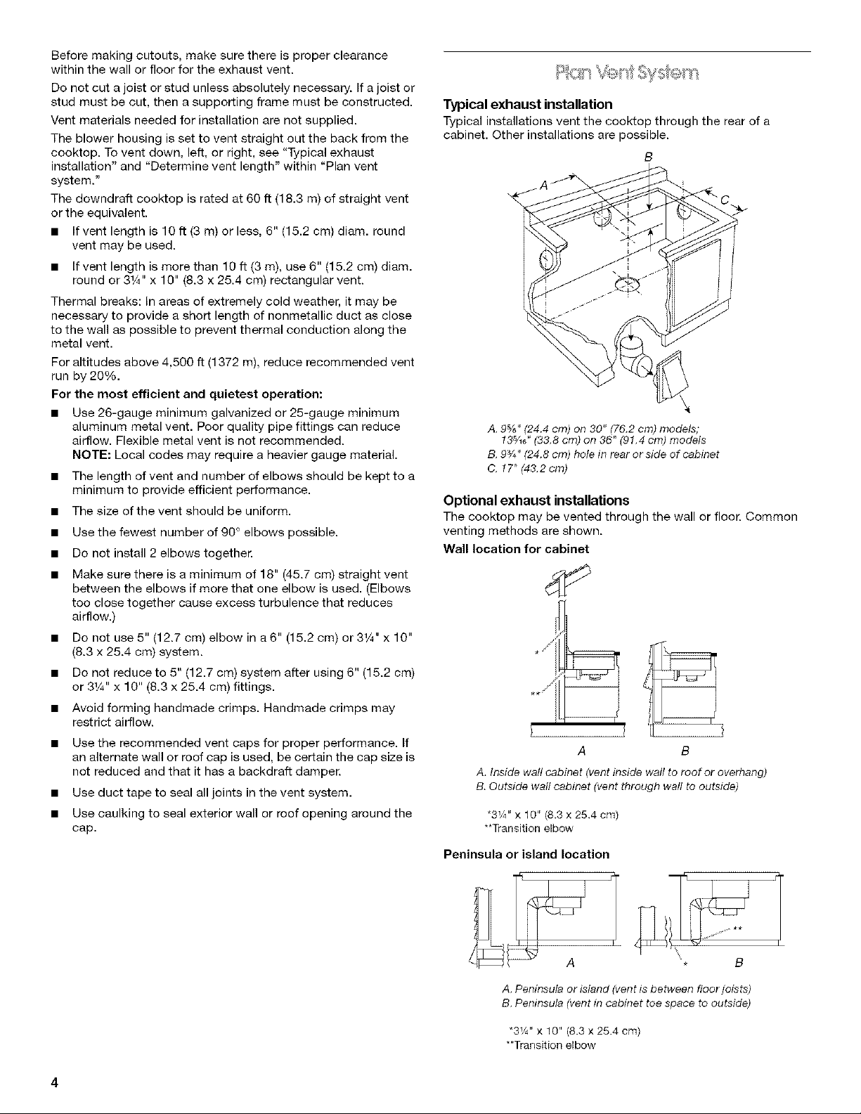
Typical exhaust installation
Typical installations vent the cooktop through the rear of a
cabinet. Other installations are possible.
B
A. 9%" (24.4 cm) on 30" (76.2 cm) models;
18s/_6" (38.8 cm) on 86" (91.4 cm) models
B. 9¾" (24.8 cm) hole in rear or side of cabinet
C. 17"(43.2cm)
Optional exhaust installations
The cooktop may be vented through the wall or floor. Common
venting methods are shown.
Wall location for cabinet
)
A B
A. Inside wall cabinet (ventinside waftto roof or overhang)
B.Outside wall cabinet (vent through wall to outside)
*3W' x 10" (8.3 x 25.4 cm)
**Transition elbow
Peninsula or island location
B
A. Peninsulaor island (ventis between floor joists)
B. Peninsula(ventin cabinet toe space to outside)
"3V4"x 10" (8.3x 25.4 cm)
**Transitionelbow
4

Alternate installations with concrete slab
Venting systems can be routed under slabs of concrete. The
exhaust may go through the wall or into a window well.
Exhaust through wall
B
E
Determine vent length
List the number of each piece and length of straight vent you will
use. Multiply the equivalent length by the number of pieces. Add
the totals to get the total equivalent length of your system.
NOTE: Maximum equivalent length is 60 ft (18.3 m).
Typical Layout
A B
C
m _ %
A. Wall cap
B. 6" (15.2 cm) round metal vent
C. 16" (40.6 cm) max.
D. 6" (15.2 cm) round
PVC sewer pipe
E. Transition
F. 6" (15.2 cm) round metal vent
G. 6" (15.2 cm) round
PVC coupling
H. Concrete slab
Exhaust into window well
A C
M
A. Waft cap
B. 12" (30.5 cm) rain.
C. Concrete slab
D. 6" (15.2 cm) round PVC
sewerpipe
E, Transition
F. 6" (15.2 cm) round
metal vent
G. 6" (15,2 cm) round
PVC coupling
K J
L 6" (15.2 cm) round PVC
sewer pipe
J. 6" (15.2 cm) round go° PVC
sewer pipe elbow
K. hghtly pack gravel or sand
completely around pipe
L. 30" (76.2 cm) max.
M. 6" (15.2 cm) round go° PVC
sewer pipe
N. 6" (15.2 cm) round PVC
coupling
O. 12" (30,5 cm) rain.
O /
K
L
H. 6" (15.2 cm) round sewer pipe
L 6" (15.2 cm) round 90° PVC
sewer pipe elbow
J. Tightly pack gravel or sand
completely around pipe
K. 42" (106.7 cm) max.
L. 6" (15.2 cm) round PVC
coupling
M. 6" (15.2 cm) min.
N. Window well
D
E
A. 2ft (61cm)
B. 6" (15.2 cm) 90° elbow
C. 4 ft (1.2 m)
D. 6" (15.2 cm) 90 ° elbow
E. 6" (15.2 cm) wall cap
F. 6 ft (1.S m)
.F
Example calculation
E
Vent Part Length
90° elbows (3) 15 ft (4.6 m)
12 ft (3.7 m) straight vent 12 ft (3.7 m)
Wall cap 0 ft (0 cm)
Total amount* 27 ft (8.3 m)
*Equivalent length for 6" (15.2 cm) round venting.
NOTE: Flexible metal vent is not recommended, if such parts are
used, calculate each 1 ft (30 cm) of flexible vent as 2 ft (61 cm) of
straight metal vent. Flexible metal elbows count twice as much
as standard elbows.