

KitchenAid KECD866RWW02 Installation Instruction
Part No. 8286553
Installation Instructions
IMPORTANT:
Installer: Leave Installation
Instructions with the homeowner.
Homeowner: Keep Installation
Instructions for future reference.
Save Installation Instructions for local
electrical inspector’s use.
Write down the model and serial numbers
before installing cooktop.
Both numbers are on the model/serial
rating plate, located on the bottom of the
cooktop.
Model #___________________________
Serial # ___________________________
IMPORTANT:
Read and save these
instructions.
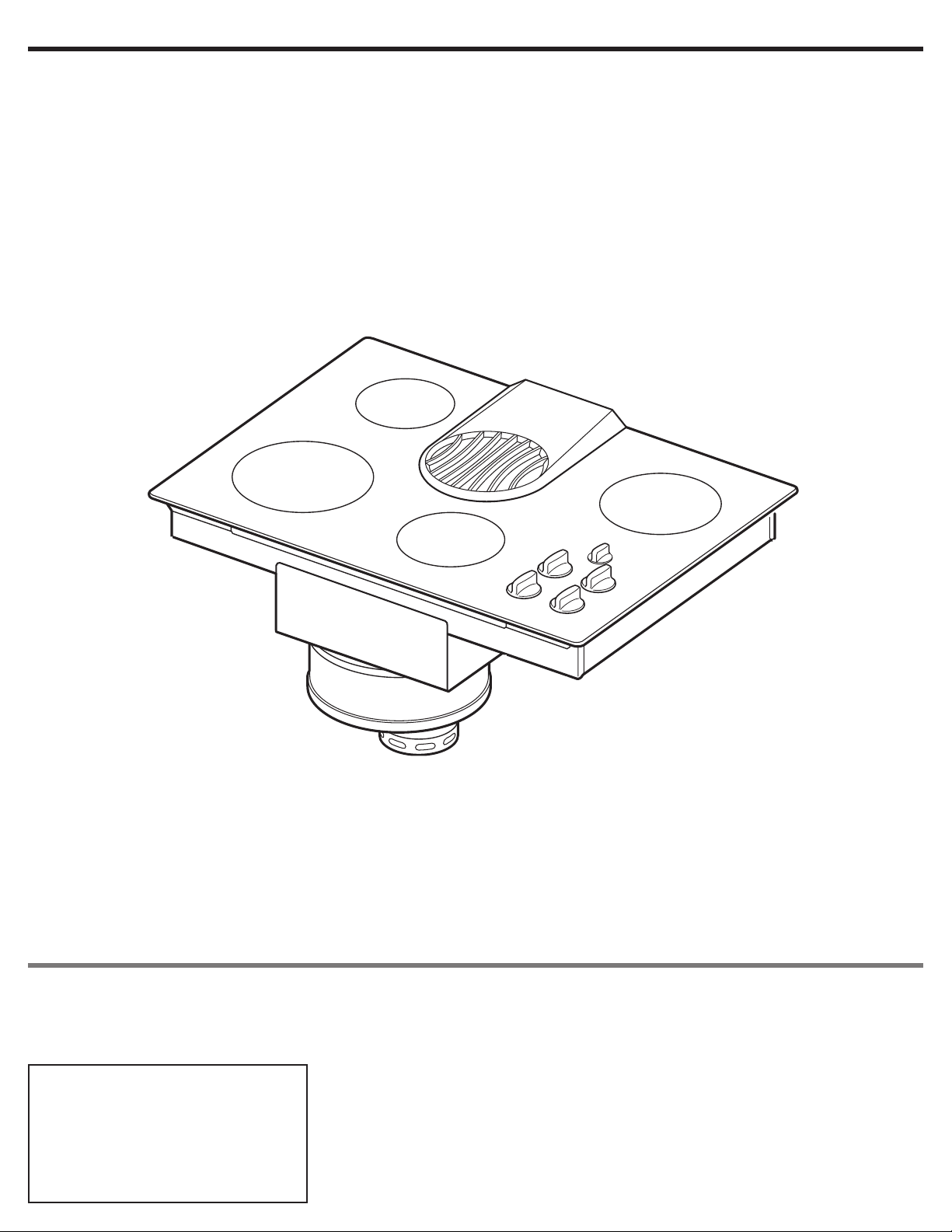
30" (
76.2 cm) and 36" (91.4 cm) ELECTRIC
Built-in Ceramic Downdraft Cooktop
Before you start...
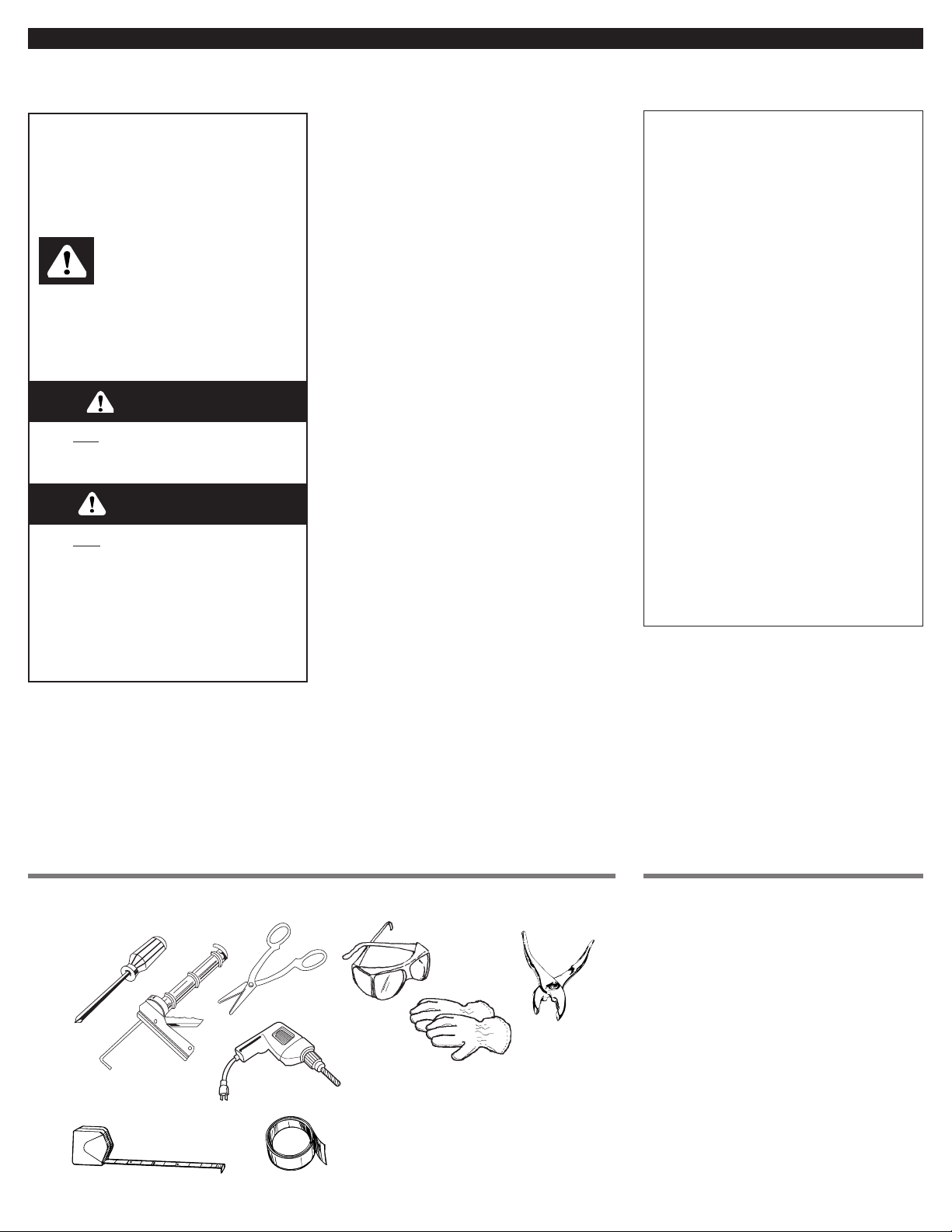
Tools and materials needed for installation:
This is the safety alert
symbol.This symbol alerts
you to hazards that can kill
or hurt you and others. All safety
messages will be preceded by the
safety alert symbol and the word
“DANGER” or “WARNING”. These
words mean:
You can
be killed or seriously
injured if you don’t follow
instructions.
DANGER
Your safety and the safety of
others is very important.
We have provided many important
safety messages in this manual and
on your appliance. Always read and
obey all safety messages.
All safety messages will identify the
hazard, tell you how to reduce the
chance of injury, and tell you what
can happen if the instructions are
not followed.
You will
be killed or seriously
injured if you don’t follow
instructions.
Parts supplied:
WARNING
2
Important: Observe all governing
codes and ordinances. Failure to meet
codes and ordinances could lead to
fire or electrical shock.
Proper installation is your responsibility.
• Make sure you have everything
necessary for correct installation.
• Have a qualified technician install
this cooktop.
• Comply with the electrical specifications
on the model/serial rating plate.
Model/serial rating plate is located on
the bottom of the cooktop. Write both
numbers down on the front cover now
before installing cooktop.
Downdraft cooktop location should be
away from strong draft areas, such as
windows, doors and strong heating vents
or fans. Locate cooktop for convenient
use in kitchen.
Grounded electrical system is required.
See “Electrical requirements,” Page 6.
Venting system must terminate
outdoors.
All openings in the wall or floor where
cooktop is to be installed must be
sealed.
It is the customer’s responsibility to
contact a qualified electrical installer,
to make sure that the electrical
installation is correct, and to make
sure the electrical installation follows
the National Electrical Code,
ANSI/NFPA 70 — latest edition*, or
CSA Standards C22.1-94, Canadian
Electrical Code, Part 1 and C22.2 No.
0-M91 - latest edition**, and all local
codes and ordinances.
tape measure
hand or
electric drill
metal
snips
duct tape
pliers
gloves
safety
glasses
caulking gun with
weatherproof caulking
Phillips
screwdriver
Not shown:
• wall or roof cap (not supplied)
• metal vent
• twist-on connector and 1/2" UL- or CSA-listed
conduit connector. Number and size will depend
on your installation. See “Electrical connection,”
Pages 6-8.
• literature pack
• vent cover
• glass cleaner
WARNING: To reduce the risk of fire,
electric shock, or injury to persons,
observe the following:
Installation work and electrical wiring
must be done by qualified person(s) in
accordance with all applicable codes
and standards, including fire-rated
construction.
Sufficient air is needed for proper
combustion and exhausting of gases
through the flue (chimney) of fuel
burning equipment to prevent back
drafting. Follow the heating equipment
manufacturer’s guideline and safety
standards such as those published by
the American Society for Heating,
Refrigeration and Air Conditioning
Engineers (ASHRAE), and the local
code authorities.
When cutting or drilling into wall or
ceiling, do not damage electrical wiring
and other hidden utilities.
Ducted fans must always be vented to
the outdoors.
WARNING: To reduce the risk of fire,
use only metal ductwork.
This downdraft cooktop is Not approved
for use in mobile homes.
Copies of the standards listed may be
obtained from:
* National Fire Protection Association
Batterymarch Park
Quincy, Massachusetts 02269
** CSA International
8501 East Pleasant Valley Road
Cleveland, Ohio 44131-5575
To eliminate the risk of burns by
reaching over heated surface units,
cabinet storage space located above
the surface units should be avoided. If
cabinet storage is to be provided, the
risk can be reduced by installing a
range hood that projects horizontally a
minimum of 5 inches (12.7 cm) beyond
the bottom of the cabinets.
3
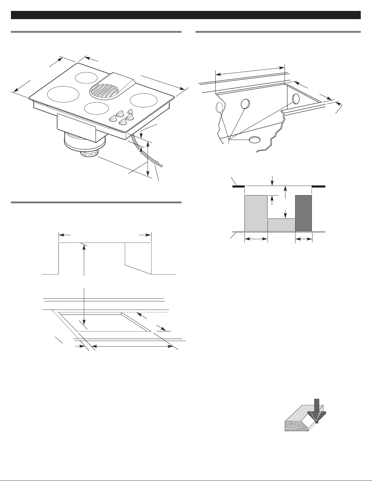
Product Dimensions Cutout Dimensions
Clearance Dimensions
21-5/16"
(54.1 cm)
depth
15-5/8" (39.6 cm)
blower housing
depth
3-ft. (91.4 cm) long
power supply cable
factory installed.
2-15/16"
(74.6 mm)
burner box
depth
Side clearance — 6" (15.2 cm) minimum clearance between side
of cooktop and side wall is recommended for maximum
ventilation performance.
Rear clearance — 3/4" (19.1 mm) clearance between rear edge of
cooktop and rear wall is recommended.
Motor/blower clearance — 2" (51 mm) minimum clearance
between motor and cabinet is required for proper cooling.
6" (15.2 cm) clearance is recommended for servicing access.
Note: 24" (61 cm) minimum when bottom of wood or metal cabinet is
protected by not less than 1/4" (6.4 mm) flame retardant millboard covered
with not less than No. 28 MSG sheet steel, 0.015" (0.4 mm) stainless steel,
0.024" (0.6 mm) aluminum or 0.020" (0.5 mm) copper.
30" (76.2 cm) minimum clearance between the top of the cooking platform
and bottom of unprotected wood or sheet metal.
**
21" (53.3 cm)
opening depth
See Note ** for
minimum clearances
Do Not seal
cooktop to countertop.
Minimum distance
to nearest combustible
vertical surface
extending 18" (45.7 cm)
above cooktop
Cutout preparation:
Decorative laminate —
Chamfer all exposed edges to
prevent chipping laminate.
Cut radius corners and file to
smooth edges and to prevent
cracking.
2" (5.1 cm) minimum
space to front edge of
countertop
Install rear
wall junction
box in shaded
area. Darker
shaded area is
preferred.
Select required duct cutout
(see Page 4 for exhaust duct
cutout location).
Countertop must be
supported within
3" (7.6 cm) of cutout.
21" (53.3 cm)
cutout depth
Minimum base cabinet dimensions —
30" (76.2 cm) base cabinet width
24" (61 cm) base cabinet depth
25" (63.5 cm) countertop depth
Countertop opening dimensions that are shown must
be used. Given dimensions are minimum clearances and
provide required 0" (0 cm) clearance.
New installations — Follow minimum dimensions given.
5" (12.7 cm)
18"
(45.7 cm)
11" (27.9 cm)
8" (20.3 cm)
countertop
floor
Replacement installation — Be sure that front edge of
cooktop is at least 1-1/2" (38.1 mm) back from front
edge of countertop.
If cabinet has drawers, drawers will need to be
removed and drawer fronts installed on front of cabinet.
29-1/2" (74.9 cm) - 30" (76.2 cm) model
35-1/2" (90.2 cm) - 36" (91.4 cm) model
cutout width
29-1/2" (74.9 cm) - 30" (76.2 cm) model
35-1/2" (90.2 cm) - 36" (91.4 cm) model
cutout width
30" (76.2 cm) min - 30" (76.2 cm) model
36" (91.4 cm) min - 36" (91.4 cm) model
when higher than 18" (45.7 cm)
30-3/8" (77.1 cm) - 30" (76.2 cm) models
36-3/8" (92.3 cm) - 36" (91.4 cm) models
width
1" (25.4 mm)
4
Venting system must terminate to the
outside.
Do Not terminate the vent system in an
attic or other enclosed space.
Do Not use 4-inch (10 cm) laundry-type
wall caps.
Use metal vent only. Exception: See
"optional venting under a concrete
slab", in "Venting methods" below.
Rigid metal vent is recommended. Do
not use plastic or metal foil vent.
To reduce risk of fire and to properly
exhaust air, be sure to vent air outside.
Do Not vent exhaust air into spaces
within walls or ceilings or into attics,
crawl spaces or garages.
Before making cutouts, make sure there
is proper clearance within the wall or
floor for the exhaust vent.
Do Not cut a joist or stud unless
absolutely necessary. If a joist or stud
must be cut, then a supporting frame
must be constructed.
Vent materials needed for installation
are not supplied.
Determine which venting method to use.
See “Venting methods,” below.
Next, determine the equivalent vent length
using chart on Page 5. The maximum
equivalent vent length is 60 feet (18.3 m).
For the most efficient and
quietest operation:
Use 26-gauge minimum galvanized or
25-gauge minimum aluminum metal
vent. Poor-quality pipe fittings can
reduce air flow. (Note: Local codes may
require a heavier-gauge material.)
Flexible metal vent is Not
recommended.
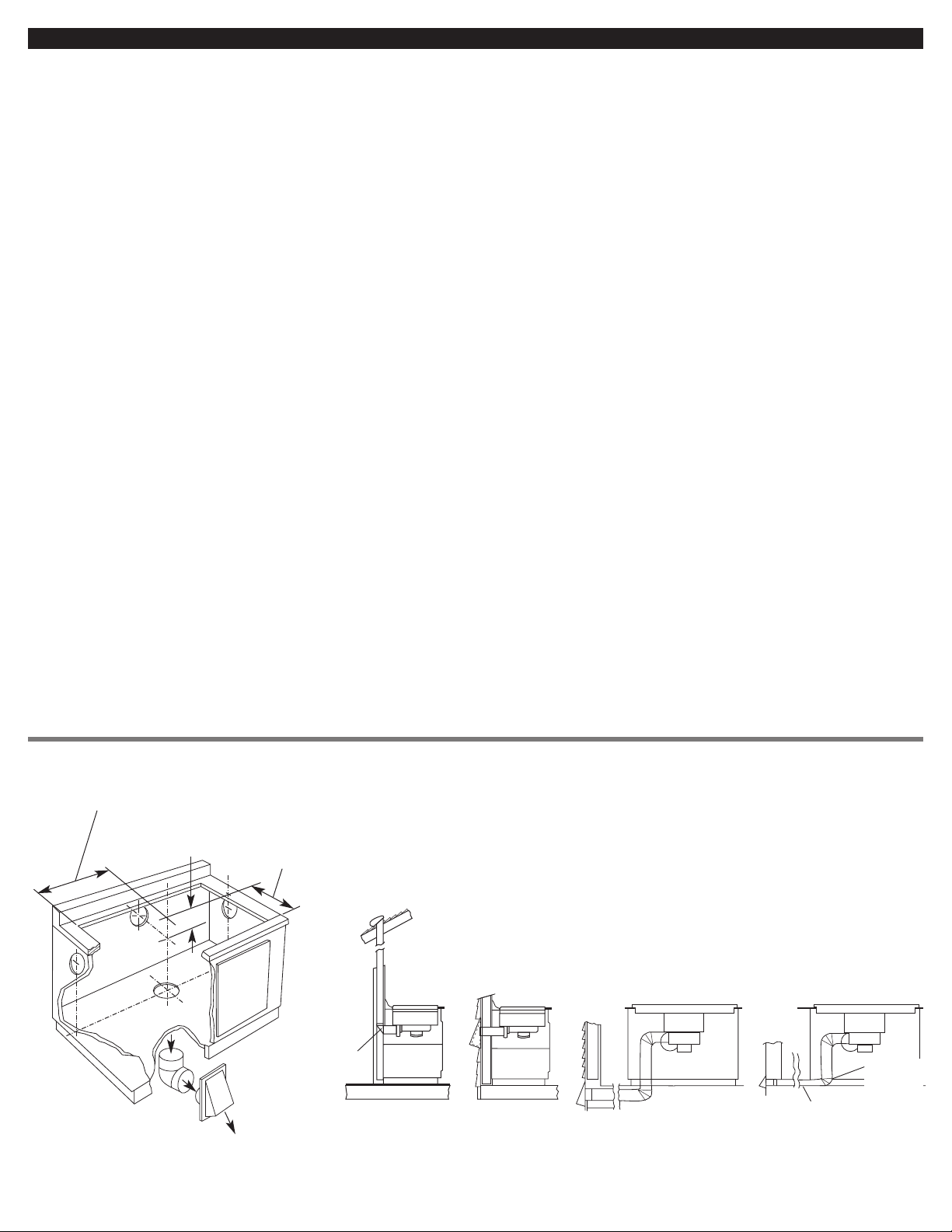
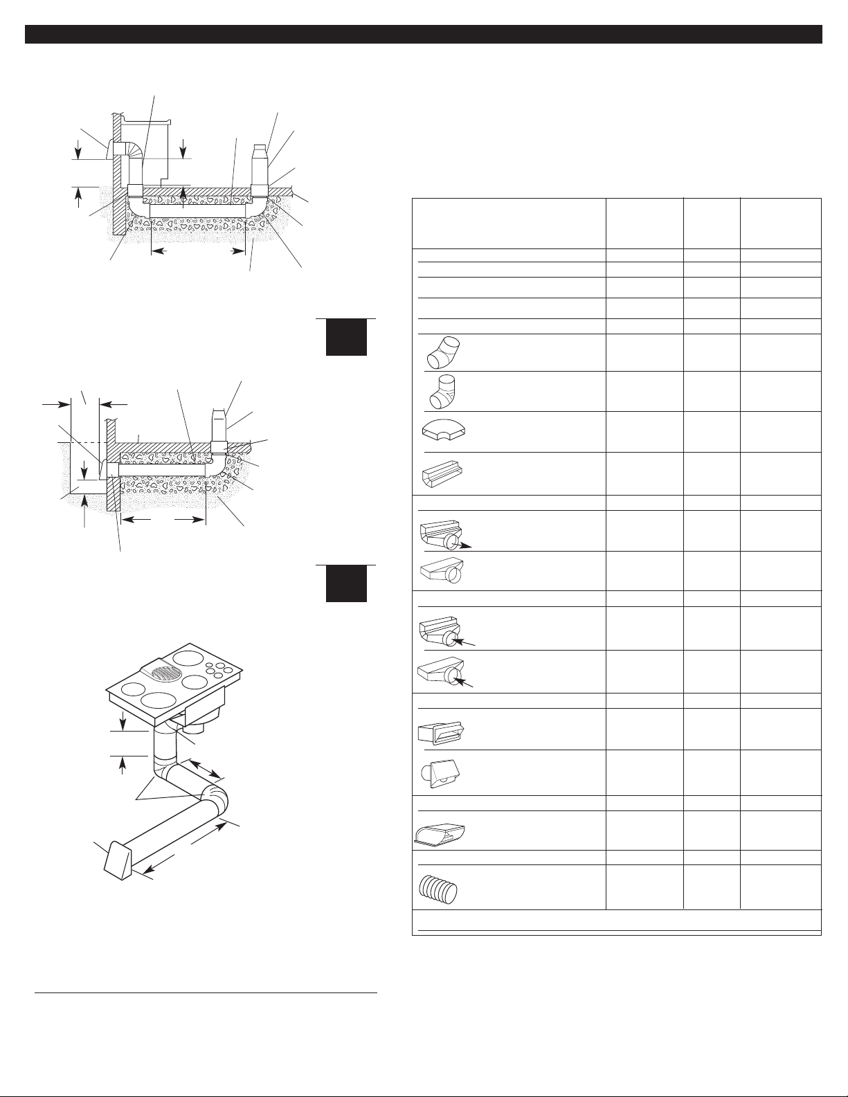
Venting system requirements
The cooktop may be vented through the wall or floor. Common venting methods and the
types of materials needed are shown.
Make sure there is proper clearance within the wall or floor for exhaust vent before
making cutouts.
17"
(43.2 cm)
9-5/8" (24.4 cm) - 30" (76.2 cm) model
13-5/16" (33.8 cm) - 36" (91.4 cm) model
9-3/4" (24.8 cm)
hole in rear or
side of cabinet
Venting methods
inside wall
cabinet
3-1/4" x 10"
(8.3 x 25.4 cm)
transition
elbow
3-1/4" x 10"
(8.3 x 25.4 cm)
transition
elbow
inside wall to roof
or overhang
outside wall
cabinet
directly
outside
peninsula
or island
peninsula
between
floor joists
cabinet toe space
to outside
The blower housing is set to vent
straight out the back from the cooktop. To
vent down, left or right, see “Installation,”
Step 2, Page 6.
This downdraft cooktop is rated at
60 feet (18.3 m) of straight vent or the
equivalent.
• If vent length is 10 feet (3 m) or less,
6" (15.2 cm) diameter round vent may
be used.
• If vent length is more than 10 feet
(3 m), use 6" (15.2 cm) diameter round
or 3-1/4" x 10" (8.3 x 25.4 cm)
rectangular vent.
Thermal breaks: In areas of extreme
cold weather, it may be necessary to
provide a short length of nonmetallic duct
as close to the wall as possible to prevent
thermal conduction along the metal vent.
For altitudes above 4,500 ft (1372 m),
reduce recommended vent run by 20%.
Do Not exhaust more than one
downdraft cooktop into a single vent
system.
The length of vent and number of
elbows should be kept to a minimum to
provide efficient performance.
The size of the vent should be uniform.
Use the fewest number of 90° elbows.
Do Not install two elbows together.
Make sure there is a minimum of 18"
(45.7 cm) of straight vent between the
elbows if more than one elbow is used.
(Elbows too close together cause
excess turbulence that reduces airflow.)
Do Not use a 5" (12.7 cm) elbow in a
6" (15.2 cm) or 3-1/4" x 10"
(8.3 x 25.4 cm) system.
Do Not reduce back to 5" (12.7 cm)
system after using 6" (15.2 cm) or
3-1/4" x 10" (8.3 x 25.4 cm) fittings.
Avoid forming handmade crimps.
Handmade crimps may restrict airflow.
Use the recommended vent caps for
proper performance. If an alternate wall
or roof cap is used, be certain cap size
is not reduced and that it has a
backdraft damper.
Use duct tape to seal all joints in the
vent system.
Use caulking to seal exterior wall or roof
opening around the cap.
5
optional vent arrangement through
window well under concrete slab
optional vent arrangement under
concrete slab
wall
cap
6" (15.2 cm)
round PVC
coupling
6" (15.2 cm)
round PVC
sewer pipe
6" (15.2 cm) round metal vent
Tightly pack gravel or sand
completely around pipe.
transition
6" (15.2 cm)
round metal vent
6" (15.2 cm)
round PVC
coupling
concrete slab
6" (15.2 cm)
round PVC
sewer pipe
6" (15.2 cm)
round 90°
PVC sewer
pipe elbow
6" (15.2 cm)
round 90° PVC
sewer pipe elbow
16" (40.6 cm)
maximum
12" (30.5 cm)
minimum
SBCCI
SBCCI
wall
cap
window
well
6"
(15.2 cm)
min.
Tightly pack gravel or sand
completely around pipe.
transition
6" (15.2 cm)
round metal vent
6" (15.2 cm) round
PVC coupling
6" (15.2 cm)
round sewer pipe
6" (15.2 cm) round
90° PVC sewer
pipe elbow
concrete
slab
6" (15.2 cm) round
PVC coupling
12" (30.5 cm)
minimum
6" (15.2 cm) round
PVC sewer pipe
Vent Equivalent No. of Total
Piece Length Pieces/ Equivalent
Length Length
straight vent per lineal foot
3-1/4" x 10" (8.3 x 25.4 cm) 1 ft. (30.5 cm)
6" (15.2 cm) round 1 ft. (30.5 cm)
6" (15.2 cm) flexible 2 ft. (61 cm)
elbow
6" (15.2 cm) round 45° elbow 2.5 ft.
(76.2 cm)
6" (15.2 cm) round 90° elbow 5 ft.
(1.5 m)
3-1/4" x 10" (8.3 x 25.4 cm) 12 ft.
flat elbow (3.7 m)
3-1/4" x 10" (8.3 x 25.4 cm) 5 ft.
90° elbow (1.5 m)
transition to round
3-1/4" x 10" (8.3 x 25.4 cm) to 9 ft.
6" (15.2 cm) 90° elbow (2.7 m)
3-1/4" x 10" (8.3 x 25.4 cm) to 4.5 ft.
6" (15.2 cm) (1.4 m)
transition to flat
6" (15.2 cm) to 3-1/4" x 10" 5 ft.
(8.3 x 25.4 cm) 90° elbow (1.5 m)
6" (15.2 cm) to 1 ft.
3-1/4" x 10" (8.3 x 25.4 cm) (30.5 cm)
wall cap*
3-1/4" x 10" (8.3 x 25.4 cm) 0 ft.
(0 cm)
6" (15.2 cm) round 0 ft.
(0 cm)
roof cap*
10" x 10" (25.4 X 25.4 cm) 0 ft.
(0 cm)
thermal break
6" (15.2 cm) round 2 ft.
(61 cm)
Total equivalent vent system length
Determine equivalent length of vent. Maximum
equivalent length of vent is 60 ft (18.3 m).
List the number of each piece and length of straight vent you will use.
Multiply the equivalent length by the number of pieces. Add the totals
to get the total equivalent length of your system.
air flow
air flow
air flow
* Length for required wall/roof cap has already been incorporated
into rating for maximum vent system length. A suitable wall/roof
cap must be used.
30" (76.2 cm)
max.
42"
(106.7 cm)
max.
6" (15.2 cm) 90° elbow
2 ft.
(61 cm)
4 ft. (1.2 m)
6" (15.2 cm)
90° elbows
6" (15.2 cm)
wall cap
Note: Flexible metal vent is Not recommended.
If it is used, calculate each foot (30 cm) of flexible vent
as two feet (61 cm) of straight metal vent. Flexible
metal elbows count twice as much as standard elbows.
90° elbows (3) = 15 ft. (4.6 m)
12 feet (3.7 m) straight = 12 ft. (3.7 m)
Wall cap = 0 ft. (0 m)
Equivalent length of = 27ft. (8.3 m)
6" (15.2 cm) round system
6 ft. (1.8 m)
Electrical requirements
Electrical connection
Installation
Electrical Shock Hazard
Turn power supply off before
connecting wires.
Use 10-gauge solid copper wire.
Electrically ground cooktop.
Failure to follow these
instructions can result in death,
fire, or electrical shock.
WARNING
Excessive Weight Hazard
Use two or more people to move
and install cooktop.
Failure to do so can result in back
or other injury.
WARNING
6
The downdraft cooktop must be
connected to the proper electrical voltage
and frequency as specified on the
model/serial rating plate. The model/serial
rating plate is located on the bottom of the
cooktop.
A four-wire or three-wire, single-phase,
240-volt, 60-Hz, AC-only electrical
supply is required on a separate
30-ampere circuit, fused on both sides
of the line.
A time-delay fuse or circuit breaker is
recommended. The fuse size must not
exceed the circuit rating of the
appliance as specified on the
model/serial rating plate.
CONNECT WITH COPPER WIRE
O N LY.
Connected directly to the fused
disconnect (or circuit breaker box)
through flexible, armored or nonmetallic sheathed, copper cable (with
ground wire).
Flexible armored cable should connect
cooktop directly to the junction box.
Fuse both sides of the line.
Locate the junction box to allow as
much slack as possible between the
junction box and cooktop so that the
downdraft cooktop can be moved if
servicing is ever necessary.
A twist-on connector and 1/2"
(12.7 mm) U.L.- or CSA-listed conduit
connector must be provided at the
junction box.
If codes permit and a separate ground
wire is used, it is recommended that a
qualified electrician determine that the
ground path is adequate.
Do Not ground to a gas pipe.
Check with a qualified electrician if you
are not sure cooktop is properly
grounded.
Do Not have a fuse in the neutral or
grounding circuit.
1. Remove shipping materials and tape
from cooktop.
2. The blower is set to vent straight out
the back of the cooktop.
To vent to the left side, right side or down
through the bottom of the cabinet, add an
elbow to the blower assembly exhaust vent.
It may be easier to connect appliance
cable to junction box before inserting
cooktop into cutout. See “Electrical
connections,” Pages 6-8.
3. Insert downdraft cooktop into cutout.
Check that:
cooktop is centered in cutout.
Lift entire cooktop up from cutout
when positioning cooktop in
countertop opening.
This cooktop must be connected to a
grounded, metallic permanent wiring
system or a ground connector should be
connected to the ground terminal or wire
lead on the cooktop.
This cooktop is manufactured with a frame
connected, green or bare ground wire. Connect
the cooktop cable to the junction box through
the 1/2" (12.7 mm) U.L.- or CSA-listed conduit
connector. Complete electrical connection
according to local codes and ordinances.
The recommended minimum copper
wire size is No.-10 gauge. However,
wire sizes and connections must conform
to the requirements of the National
Electrical Code, ANSI/NFPA 70 — latest
edition*, or CSA Standards C22.1-94,
Canadian Electrical Code, Part 1 and
22.2
No. 0-M91 - latest edition** and all local
codes and ordinances. Wire sizes and
connections must conform with the rating
of the cooktop.
Copies of the standard listed may be obtained from:
* National Fire Protection Association
Batterymarch Park
Quincy, Massachusetts 02269
** CSA International
8501 East Pleasant Valley Road
Cleveland, Ohio 44131-5575
The wiring diagram is located on the
bottom of the cooktop.
Twist-on connector and 1/2" (12.7 mm)
U.L.- or CSA-listed conduit connector are
not provided.
5. Make the electrical connection:
front edge of downdraft cooktop is at least
1-1/2" (38.1 mm) from front edge of
countertop and parallel to countertop.
rear edge of cooktop is at least 3/4"
(19.1 mm) from rear wall as recommended.
side edge of cooktop is at least 6 inches
(15.2 cm) from side wall.
4. Connect vent system. See “Venting
requirements,” Pages 4-5. Use duct tape to
seal all joints. Vent must end with a wall or
roof cap outside the building.
 Loading...