

KitchenAid KECD806RSS03, KECD866RBL00, KECD866RBL03, KECD866RBL02, KECD866RSS00 Installation Guide
...Page 1
ui
C
Readandsavethese
IMPORTANT:
Installer: Leave HnstaHation
Hnstructions with the homeowner.
Homeowner: Keep hstaHation
Hnstructions for future reference.
Save hstaHation hstructions for HocaH
eHectricaHinspector's use.
Write down the modeHand seriaHnumbers
before installing cooktop.
Both numbers are on the modeH/seriaH
rating pilate, Hocatedon the bottom of the
cooktop.
ModeH#
Serial #
Part No. 8286553
Page 2
Before youstart...
Your safety and the safety of
others is very important.
We have provided many important
safety messages in this manual and
on your appliance, Always read and
obey all safety messages,
This is the safety alert
symbol,This symbol alerts
you to hazards that can kill
or hurt you and others, All safety
messages will be preceded by the
safety alert symbol and the word
"DANGER" or "WARNING", These
words mean:
You will be kilted or seriously
injured if you don't foIIow
instructions.
You can be kilted or seriously
injured if you don't follow
instructions.
All safety messages will identify the
hazard, tell you how to reduce the
chance of injury, and tell you what
can happen if the instructions are
not followed,
To eliminate the risk of burns by
reaching over heated surface units,
cabinet storage space located above
the surface units should be avoided, if
cabinet storage is to be provided, the
risk can be reduced by instalming a
range hood that projects horizontally a
minimum of 5 inches (12.7 cm) beyond
the bottom of the cabinets.
Important: Observe aH governing
codes and ordhances. Failure to meet
codes and ordinances could lead to
fire or electrical shock.
Proper installation is your responsibility.
, Make sure you have everything
necessary for correct installation.
° Have a qualified technician instatl
this cooktop.
,, Comply with the electrical specifications
on the model/serial rating plate.
Model/serial rating plate is located on
the bottom of the cookto F Write both
numbers down on the front cover now
before installing cooktoF
Downdraft cooktop location should be
away from strong draft areas, such as
windows, doors and strong heating vents
or fans. Locate cooktop for convenient
use in kitchen.
Grounded electrical system is required.
See "Electrical requirements," Page 6.
Venting system must terminate
outdoors.
A[[ openings [n the wail or floor where
cooktop is to be installed must be
seaJed.
It [s the customer's responsibility to
contact a qualified eJectrica[ hstaHer,
to make sure that the e_ectrical
hstaImation is correct, and to make
sure the electrical installation follows
the National Electrical Code,
ANSI/NFPA 70 i [atest edition*, or
CSA Standards 022.1-94, Canadian
Electrical Code, Part 1 and C22.2 No.
0-M91 - latest edition**, and am[ Iocam
codes and ordhancea.
WARNING: To reduce the risk of fire,
electric shock, or injury to persons,
observe the following:
Installation work and electrical wiring
must be done by qualified person(s) in
accordance with aii applicable codes
and standards, including fire-rated
construction.
Sufficient air is needed for proper
combustion and exhausting of gases
through the flue (chimney) of fuel
burning equipment to prevent back
drafting. Follow the heating equipment
manufacturer's guideline and safety
standards such as those published by
the American Society for Heating,
Refrigeration and Air Conditioning
Engineers (ASHRAE), and the local
code authorities.
When cutting or drilling into wail or
ceiling, do not damage electrical wiring
and other hidden utilities.
Ducted fans must always be vented to
the outdoors.
WARNING: To reduce the risk of fire,
use only metal ductwork.
This downdraft cooktop is Not approved
for use in mobib homes.
copies of the standards listed maybe
obtainedfrom:
* National FireProtectionAssociation
BatterymarchPark
Quincy, P4assachusetts 02269
** CSA [nterrnationaI
8501 East Pleasant Valley Road
Cleveland, Ohio 44131=5575
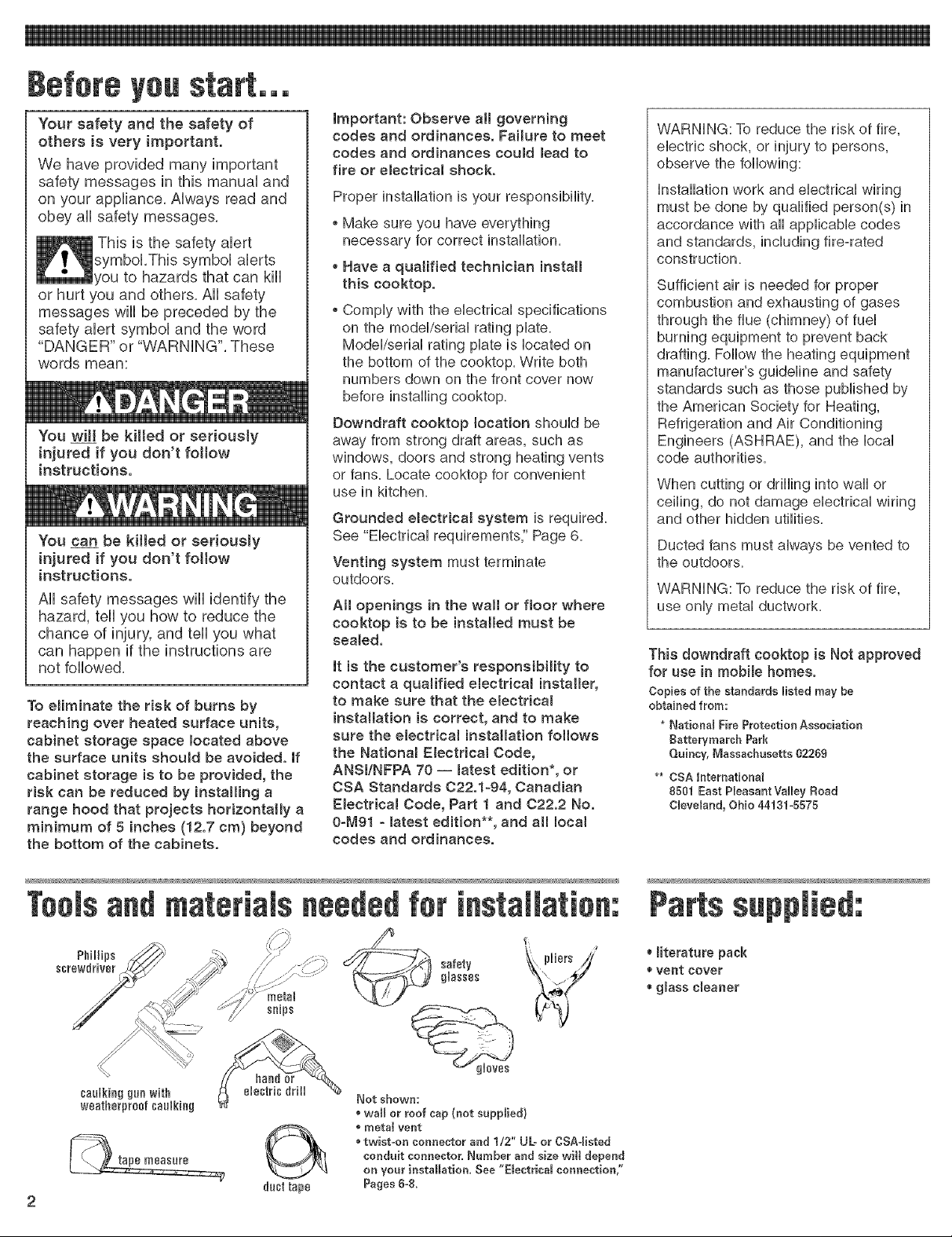
Toolsand materials neededfor installation:
Phillips _::_ __1 f\, pliers //
screwdriver Z" / j -y safety
Not shown:
* wall or roof cap (not supplied}
recta[ vent
twist-on connector and 1/2" UL- or CSA-Iisted
conduit connector, Number and size wi[[ depend
on your installation, See "E[ectdca[ connection,"
Pages 6-8.
Parts supplied:
* Biterature pack
_,vent cover
gBass cleaner
Page 3
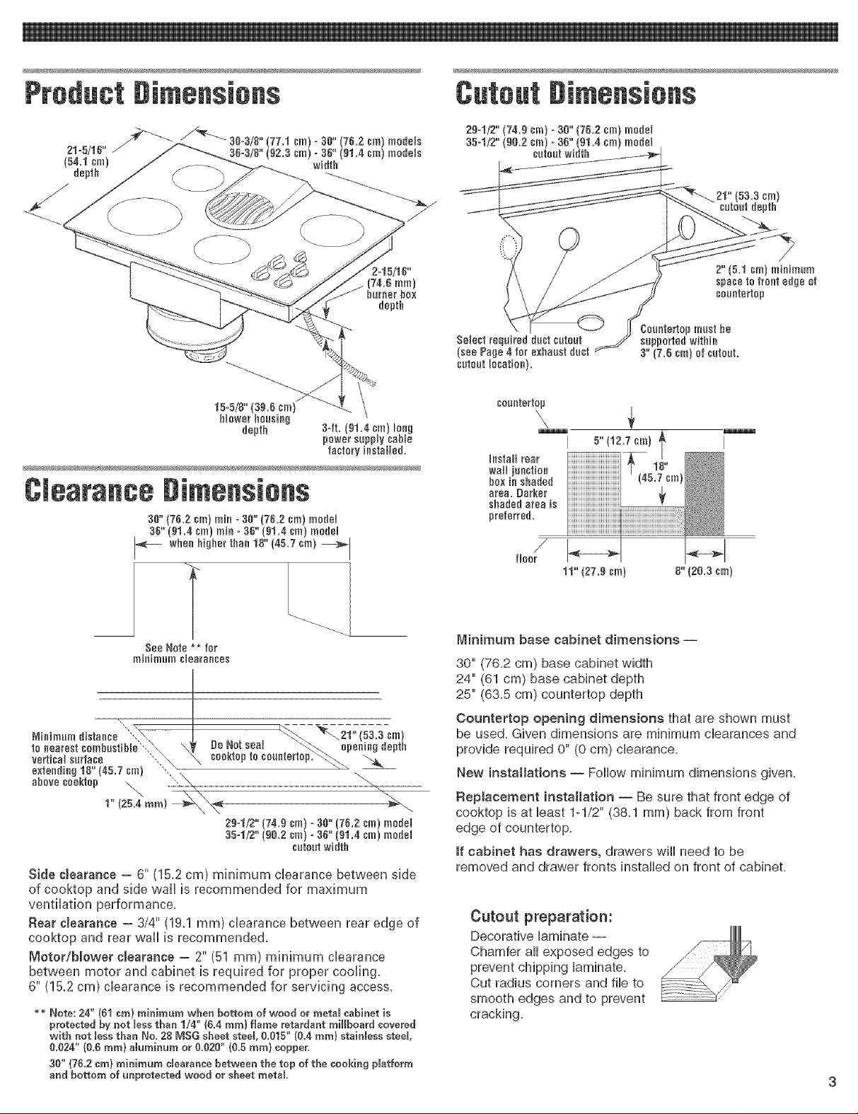
Product #[mens[ens
2-15/16"
j (74.6 mml
burner box
depth
Cateut#imensiens
cm)
_pth
15-5/8" (3&6 cm)
blower housing
depth
34t. 91.4 cm long
power suppy cab e
factory installed.
Clearancegimensiens
30" (762 cm) min =3g" (7&2 cm) model
36" (91.4 cm) min =36" (gl.4 cm) model
_- wbee higher thee 18" (45.7 cm) _1
See Note ** [or
minimum clearaeces
b
Nieiraumdistaece,i_ I. _ . , _ _\21"(5a.a cm)
to nearest oombostiNe"_\ \_, ue !.Jo_seal _.r_\ opening depth
vertical surface "..._ \ ceo,'neple ceoiHenep. -_......
extending 18" 4&7 cm) ',.,_ " " _--
above ceoktep _. ....:_.\_ ...............................................................................................................................................................................................
Side clearance - 6" (15.2 cm) minimum clearance between side
N I
29=1/2" (74.9 cm) ° 30" (7&2 cm) model
354/2" (96.2 cm) =36" (91.4 cm) model
cutout width
B
coontertop
5" (12.7 em)
_estall rear
wall junction
box ie shaded
area. #arker
shaded area is
preferred.
Minimum base cabinet dimensions i
30" (76,2 cm) base cabinet width
24" (61 cm) base cabinet depth
25" (63,5 cm) countertop depth
Countertop opening dimensions that are shown must
be used, Given dimensions are minimum clearances and
provide required 0" (0 cm) clearance,
New installations i Follow minimum dimensions given,
Replacement installation i Be sure that front edge of
cooktop is at least 1=1/2" (38,1 mm) back from front
edge of countertop,
If cabinet has drawers, drawers will need to be
removed and drawer fronts installed on front of cabinet,
of cooktop and side wall is recommended for maximum
ventilation performance.
Rear cJearance = 3/4" (19,1 mm) clearance between rear edge of
cooktop and rear wall is recommended.
Motor/blower clearance -- 2" (51 mm) minimum clearance
between motor and cabinet is required for proper cooling.
6" (15.2 cm) clearance is recommended for servicing access.
_ Note: 24" {01 era} rainiraura when bottom of wood or rectal cabinet is
protected by not less than 1/4" {0.4 rare} flarae retardant raillboard covered
with not Jessthan No. 28 MSG sheet steel, 0.015" (0.4 rare} stainless steel,
0.624" (0,0 rare} alurainura or &O20" (0,5 rare} copper,
30" {76,2 era) rainiraura cJearancebetween the top of the cooking platforra
and bottom of unprotected wood or sheet rectal,
Cutout preparation:
Decorative laminate --
Chamfer all exposed edges to
prevent chipping laminate,
Cut radius corners and file to
smooth edges and to prevent
cracking=
I
Page 4

Ventingsystemrequirements
Venting system must terminate to the
outside.
Do Not terminate the vent system in an
attic or other enclosed space.
Do Not use 4-inch (10 cm) laundry-type
wall caps.
Use metal vent only. Exception: See
"optional venting under a concrete
stab"", in "Venting methods" below.
Rigid metat vent is recommended, Do
not use plastic or metat foil vent,
To reduce risk of fire and to properly
exhaust air, be sure to vent air outside,
Do Not vent exhaust air into spaces
within walls or ceilings or into attics,
crawl spaces or garages.
Before making cutouts, make sure there
is proper clearance within the wall or
floor for the exhaust vent.
Do Not cut a joist or stud unless
absolutely necessary, if a joist or stud
must be cut, then a supporting frame
must be constructed.
Vent materials needed for hstaHation
are not supplied,
Determine which venting method to use.
See "Venting methods," below.
Next, determine the equivalent vent length
using chart on Page 5. The maximum
equivalent vent length is 60 feet (18.3 m).
The blower housing is set to vent
straight out the back from the cooktop. To
vent down, left or right, see "installation,"
Step 2, Page 6.
This downdraft cooktop is rated at
50 feet (18.3 re) of straight vent or the
equivament,
o If vent mength is 10 feet (3 re) or less,
6" (15.2 cm) diameter round vent may
be used.
o if vent length is more than 10 feet
(3 m), use 6" (152 cm) diameter round
or 3ol/4" x 10" (8.3 x 25.4 cm)
rectangular vent.
Therma[ breaks: in areas of extreme
cold weather, it may be necessary to
provide a short length of nonmetallic duct
as close to the wall as possible to prevent
thermal conduction along the metal vent.
For attitudes above 4,500 ft (1372 m),
reduce recommended vent run by 20%.
For the most efficient and
quietest operation:
[] Use 26-gauge minimum galvanized or
25-gauge minimum aluminum metal
vent. Poor-quality pipe fittings can
reduce air flow. (Note: Local codes may
require a heavier-gauge materiaL)
Flexible metal vent is Not
recommended.
[] Do Not exhaust more than one
downdraft cooktop into a single vent
system.
[] The length of vent and number of
elbows should be kept to a minimum to
provide efficient performance.
[] The size of the vent should be uniform.
[] Use the fewest number of 90 ° elbows.
[] Do Not install two elbows together.
[] Make sure there is a minimum of 18"
(45.7 cm) of straight vent between the
elbows if more than one elbow is used.
(Elbows too close together cause
excess turbulence that reduces airflow.)
[] Do Not use a 5" (12.7 cm) elbow in a
6" (15.2 cm) or 3ol/4" x 10"
(8.3 x 25.4 cm) system.
[] Do Not reduce back to 5" (12.7 cm)
system after using 6" (15.2 cm) or
3ol/4" x 10" (8.3 x 25.4 cm) fittings.
[] Avoid forming handmade crimps.
Handmade crimps may restrict airflow.
[] Use the recommended vent caps for
proper performance, if an alternate wall
or roof cap is used, be certain cap size
is not reduced and that it has a
backdraft damper.
[] Use duct tape to seal all joints in the
vent system.
[] Use caulking to seal exterior wall or roof
opening around the cap.
Venting methods
9=5/8" (24,4 ¢m) =30" (70.2 sm) m0del
13=5/lt_" ,0 sm) =30" (01,4 sm) m0del
9=3/4" (24.8 sin)
h01ein rear or
side of cabinet
The cooktop may be vented through the wall or floor. Common venting methods and the
types of materials needed are shown.
Make sure there is proper clearance within the wall or floor for exhaust vent before
making cutouts.
3=1/4"x 10"
(0,3 x 25.4 em
transition
elbow
sabinet er island
ll outside wall _ peninsula
inside wall to roof directly between
or overhang outside floor joists
peninsula
a=1/4"x lO"
(0.3x 25.4sin}
cabinettoe space
to outside
Page 5

12".(30.5sra)
ram]raUra
6" (15.2 era) reund metal vent
Determine equivalent length of vent. Maximum
equivalent length of vent is 60 ft (18.3 m).
List the number of each piece and length of straight vent you will use.
Multiply the equivalent length by the number of pieces. Add the totals
to get the total equivalent length of your system.
6" (15.2 cra)
round PVC
coupling /
6" (15,2 era)
round 90° PVC
sewer pipe elbow
/
(76.2 cra) ;_ sewer pipe
max. \ 6" (15,2 era)
Tightly pack gravel or sand round 90°
completely around pipe. PVC sewer
6" (15,2 era)
round PVC
pipe elbow
optional vent arrangement under
concrete slab
12" (30.5 cra) 6" (15.2 era} round transition
minimum PVC sewer pipe /6" (15.2 cra)
wall 1 _ 6" (15,2 cra) round
cap PVC coupling
well
6" (106,7cra)
(15.2 era) i max.
rain. 6" (15,2 era) round
PVC coupling
round raetal vent
5" (15.2 cra)
round sewer pipe
5" (15.2 era) round
g0° £VC sewer
pipe elbow
Tightly pack gravel or sand
completely around pipe.
optional vent arrangement through
window well under concrete slab
Vent
Piece
straight vent per lineal foot
3-I/4" x 10" (8.3 x25.4 cm)
6" (152 crn) round
6" (15,2 crn) flexible
elbow
6" (152 crn) round 45° elbow
6" (15,2 crn) round 90° elbow
_--_ 3-1/4" x 10" (8.3 x 25,4 crn)
_:,5 3:_ flat elbow
3-1/4" x 10" (8.3 x 25,4 crn)
90° elbow
transition to round
_-:-_-_m 3-1/4" x 10" (8.3 x 25.4 crn) to
_i _ air flow
_ -1/4" x 10" (8.3 x 25,4 crn) to
6" (152 crn)
transition to flat
......._m 6" (15.2 crn) to 3q_4" x 10"
_iL(8.3x2&4crn) 90 elbow
.....L_2"_ air flow
_ ;_:/-; 6" (15,2 crn) to
?-¢_ _ i_;_3-1/4" x 10" 8.3 x 25,4 crn)
':_ air flow
wall cap*
x 10" (8.3 x 25,4 crn)
Equivalent
Length
1ft, (30.5era)
1ft. (30.5era)
2ft. (61era)
2.5 ft,
(76.2 era)
5 ft.
(1.5 ra)
12 ft.
(3.7 ra)
5 ft.
(1.5 ra)
9 ft.
(2.7 ra)
4.5 ft,
(1.4 ra)
5 ft.
(1.5 ra)
I ft.
(30.5era)
0 ft.
(0era)
No. of
Pieces/
Length
Total
Equivalent
Length
6" (15,2 era}
900 elbows
6" 15.2 cm
wa cap
\
6 ft, (1,8 m)
90° elbows (3) = 15ft. (4.6 m)
12 feet (3.7 m) straight = 12ft. (3.7 m)
Wall cap = 0ft.(0m}
Equivalent length of
= 27ff. (8.3 m)
6" (15.2cm) round system
Note: Flexible metal vent isNet recommended.
If it is used, calculate eachfoot (30 cm) of flexible vent
astwo feet (61 cm) of straight metal vent. Flexible
metal elbows count twice as much as standard elbows.
_ 6" (15,2crn) round
roof cap*
lO.x18,, x284
thermal break
0 ft.
(0era)
0 ft.
(0era)
2ft.
-/_ 6" (15,2crn) round
Total equivalent vent system length
(61era)
* Length for required wall/roof cap has already been incorporated
into rating for maximum vent system length. A suitable wall/reef
cap must be used.
Page 6

if codespermitandaseparateground
wireisused,itisrecommendedthata
qualifiedelectriciandeterminethatthe
groundpathis adequate.
Do Not ground to a gas pipe.
Check with a qualified electrbian if you
are not sure cooktop is properly
grounded.
Do Not have a fuse in the neutral or
grounding circuit.
The down@aft cooktop must be
connected to the proper electrical voltage
and frequency as specified on the
model/serial rating plate. The model/serial
rating plate is located on the bottom of the
cooktop.
[] A four-wire or three-wire, singb-phase,
240-volt, 60-Hz, AC-only electrical
supply is required on a separate
30-ampere circuit, fused on both sides
of the line.
[] A time-delay fuse or circuit breaker is
recommended. The fuse size must not
exceed the circuit rating of the
appliance as specified on the
model/serial rating plate.
[] CONNECT WITH COPPER WIRE
ONLY.
[] Connected directly to the fused
disconnect (or circuit breaker box)
through flexible, armored or non °
metallic sheathed, copper cable (with
ground wire).
[] Flexible armored cable should connect
cooktop directly to the junction box.
[] Fuse both sides of the fine.
[] Locate the junction box to allow as
much slack as possible between the
junction box and cooktop so that the
downdraft eooktop can be moved if
servicing is ever necessary.
[] A twist=on connector and 1/2"
(12.7 mm) U.L o or CSA=listed conduit
connector must be provided at the
junction box.
The recommended minimum copper
wire size is No.-lO gauge. However,
wire sizes and connections must conform
to the requirements of the National
Electrical Code, ANSI/NFPA 70 -- latest
edition*, or CSA Standards C22.1-94,
Canadian Electrical Code, Part 1 and
22.2
No. 0-M91 - latest edition** and all local
codes and ordinances. Wire sizes and
connections must conform with the rating
of the cooktop.
Copiesofthe standardlistedmaybeobtainedfrom:
* National FireProtection Association
BatterymarchPark
Quincy,Massachusetts02269
** CSA International
8501 East Pleasant Valley Road
CleveRand,Ohio 44131o5575
The wiring diagram is located on the
bottom of the cooktop.
Twist-on connector and 1/2" (12.7 ram)
U.L o or CSA-listed conduit connector are
not provided.
E Remove shipping materials and tape
from cooktop.
The blower is set to vent straight out
the back of the cooktop.
To vent to the left side, right side or down
through the bottom of the cabinet, add an
elbow to the blower assembly exhaust vent.
It may be easier to connect appliance
cable to junction box before inserting
cooktop into cutout. See "Electrical
connections," Pages 6-8.
Excessive Weight Hazard
Use two or more peopte to move
and install cooktop.
Failure to do so can result in back
or other injury.
[] front edge of downdraft cooktop is at least
lq/2" (38.1 ram) from front edge of
countertop and parallel to countertop.
[] rear edge of cooktop is at least 3/4"
(19.1 ram) from rear wall as recommended.
[] side edge of cooktop is at least 6 inches
(152 cm) from side wall.
m Connectvent system.See"Venting
requirements,"Pages4=5.Useduct tapeto
sea!all joints.Ventmustend witha wallor
roofcap outsidethe building.
This cooktop must be connected to a
grounded, metallb permanent wiring
system or a ground connector shoumd be
connected to the ground terminam or wire
bad on the cooktop.
This cooktop is manufactured with a frame
connected, green or bare ground wire. Connect
the cooktop cable to the junction box through
the 1/2" (1£7 mm) U.L.=or CSA-listed conduit
connector. Complete electrical connection
according to local codes and ordinances.
Make the electrical connection:
Lift entire cooktop up from cutout
when positioning cooktop in
countertop opening.
3m insert downdraft cooktop into cutout.
Check that:
[] cooktop is centered in cutout.
Electrical Shock Hazard
Turn power supply off before
connecting wires.
Use !O-gauge solid copper wire.
Electrically ground cooktop.
Failure to follow these
instructions can result in death,
fire, or etectricaJ shock.
Page 7

I For all cooktop models with three-wire cable from the cooktop:
Where tocal codes Do Not permit connecting the frame-
ground conductor to the neutral (white) junction box
wire. (Used for Canadian installations):
4=wire cable from power supply
red wires _Junctiee box
Ungrounded
neutra_ j
Figure 1
1oDisconnect wires
power supp{yo 3-wire cable conduit connector
bare or green
white wire
twist-on
connector
U,L,- or CSA- listed
2oRemove the junction fromcooktop
box cover from the junction box inside the cabinet,
3oConnect the flexible, armored cable from the cooktop to the
junction box using a U=L=or CSAqisted conduit connector,
Tighten screws on conduit connector.
4, Connect the two black wires together; then connect the two red
wires together using twist-on connector. (See Figure 1.)
5, Connect the green or bare ground wire from the cooktop cable
to the grounded wire in the junction box or other grounded
connector using twist-on connector,
6oPut a twist-on connector on end of white wire. Do Not connect
bare ground wire to neutra8 (white) wire in junction box,
7. Replace the junction box cover,
Where Jocal codes permit connecting the frame-ground
conductor to the neutral (white) junction box wire. (Not
used for Canadian installations):
3=wire cable from power supply
Groundedneutra_Figure2 redwiL_ __nestor_--q_r'--,._/junctiontwist-onbox
bare or J -"
white _ _ Mack wires
green wire
1. Disconnect from cooktop _ conduit connector
power supply.
2. Remove the junction box cover from the junction box inside
the cabinet,
3. Connect the flexible, armored cable from the cooktop to the
junction box using a U,L- or CSAqisted conduit connector,
Tighten screws on conduit connector,
4. Connect the bare cooktop wire with the white wire; the two
red wires together; and the two black wires together using
twist-on connectors, (See Figure 2,)
5. Replace the junction box cover,
3-wire cable _J _ U.L- or CSA- listed
For aH cooktop models with four-wire cable from the cooktop. (These cooktops are manufactured with white
[neutron] power supply wire and a cabinet-connected bare ground wire factory-crimped together.):
Where tocaJ codes Do Not permit connecting the frame-
ground conductor to the neutraJ (white) junction box
wire: (Used for Canadian installations):
4-wire cable from power supply
red wires J junction box
_J
U ng re u n ded _ white wires
Where tocaJ codes permit connecting the frame-ground
conductor to the neutraJ (white) junction box wire. (Not
used for Canadian installations):
3-wire cable from
junction power supply
box
red
black
neutra_
Figure 4
Figure 3 _ \twist=on
green
wires
1o Disconnect 4-wire cable
power supplyo from cookto \ U,L,- or CSA- listed
2. Remove the junction
J '_Mack wires
conduit coneector
cormector
box cover from the junction box inside the cabinet,
3. Connect the flexible, armored cable from the cooktop to the
junction box using a U=L- or C=S=A=qistedconduit connector,
Tighten screws on conduit connector,
4. Connect the two black wires together; then connect the two red
wires together using twist-on connectors, (See Figure 3,)
5. Separate the factory-crimped bare and white cooktop cable wires,
6oConnect the two white wires together using twist-on connectors,
7. Connect the bare ground wire from the cooktop cable to the
grounded wire in the junction box or other grounded connector
using twist-on connector, (See Figure 3,)
Do Not connect bare ground wire to neutron (white) wire in
1. Disconnect 4-wire cable from cooktop connector
power supply.
2oRemove the junction
box cover from the junction box inside the cabinet,
3oConnect the flexible, armored cable from the cooktop to
the junction box using a U,L- or C,S,A,qisted conduit
connector, Tighten screws on conduit connector,
4, Connect the two black wires together; the two red
wires together; and the factory=crimped bare and
white cooktop cable wires to the white (neutral) wire
in the junction box using twist-on connectors, (See
Figure 4,)
5. Replace the junction box cover,
white
wire
white and
grounding oven cable
wires -- factory U,L,- or CSA-
crimped listed conduit
junction box.
8. Replace the junction box cover=
Page 8

For all cooktop models with four-
wire cable from the cooktop.
(:These cooktops are
manufactured with white
(neutra 0 power suppJy wire and
a cabinet-connected bare ground
wire factory-crimped together.):
Where tocal codes Do Not permit
connecting the frame-ground
conductor to the neutra! (white}
junction box wire:
1, Disconnect power supply.
2, Remove the junction box cover from
the junction box inside the cabinet.
3, Connect the flexible, armored cable
from the cooktop to the junction box
using a U.L =or C.S.A.qisted conduit
connector. Tighten screws on conduit
connector.
4, Connect the two black wires together
and the two red wires together.
5. Separate the factory-crimped bare and
white cooktop cable wires.
6, Connect the two white wires together
using twist-on connectors.
7, Connect the bare ground wire from the
cooktop cable to a grounded wire in
the junction box or other grounded
connector using twist-on connector.
(See Figure 3.)
Do Not connect bare ground wire to
neutral (white) wire in junction box,
8. Replace the junction box cover.
Check operation
Turnon electricalsupply.
71 Check that cooktop surface elements
heat and indicator lights are operating correctly.
8B Checkthat downdraftvent operates,if
thecooktop does not operate,disconnectthe
powersupplyand checkthat wire connections
havebeen madecorrectly.
You have just finished installing your
new downdraft cooktop. To get the
most efficient use from your new
cooktop, read your Use & Care Guide.
Keep Installation instructions and
Guide close to cooktop for easy
reference.
Ceektepremevam
tf removing the cooktop is necessary
for cJeaning or maintenance:
1. Disconnect electrical supply.
2. Disconnect ventsystem.
3. Lift cooktop out of countertop to
complete cleaning or maintenance.
After cJeaning and maintenance:
1. Reinstall cooktop in cutout.
2. Check that front edge of cooktop is
parallel to front edge of countertop.
3. Connect vent system.
4. Connect electrical supply.
If ceektep
net eperate:
[_ Check that the circuit breaker is not
tripped or the house fuse blown.
[_ Check that the power supply cord is
plugged into the outlet (120 V models).
[_See Use and Care Guide for
troubleshooting list.
Note: Refer to Use and Care Guide for
operating and cleaning instructions.
If youneed
if you have questions about
operating, cJeaning or maintaining
your cooktop:
[_ Refer to Use and Care Guide,
[_ Call the Customer Interaction Center.
Check your Use and Care Guide for
a toll-free number to call or call the
dealer from whom you purchased
this appliance. The dealer is listed in
the Yellow Pages of your phone
directory under "Appliances --
Household -- Major -- Service and
Repair."
Maintain the quality buitt into your
cooktop by calling an authorized
service company.
To obtain the name and number of the
authorized service company:
[_ Contact the dealer from whom you
purchased your cooktop; or
[_ Look in the Yellow Pages of your
telephone directory under
"Appliances -- Household --
Major -- Service and Repair;" or
[_ Call the Customer Interaction Center.
The toIFfree number is listed in your
Use and Care Guide.
When you call, you will need:
E_The cooktop model number.
E_The cooktop serial number.
Both numbers are listed on the
model/serial rating plate located on the
underside of cooktop burner box.
Part No. 8286553 Printed in U.S.A.
Q 2005 Whirlpool Corporation Benton Harbor, Michigan 49022 04/2005
Page 9

NOTES
Page 10

NOTES
10
 Loading...