

KitchenAid KECD805EWH0 Installation Instruction

Installation Instructions
Quick Reference
Table of Contents:
Pages
1 Before you start
q
1 Cutout dimensions
q
1 Clearance dimensions
q
1 Product dimensions
q
1 Tools and materials needed
q
1 Parts supplied
q
m-i-5-j Venting requirements
4 Electrical requirements
q
m-1 Installation steps
-1 Cooktop removal
Back cover If cooktop does not operate
m If you need assistance
[Back] If you need service
30”
ELECTRIC
Built-in Ceramic
Downdraft Cooktop
Need assistance?
Call the KitchenAid Consumer Assistance Center at l-800-422-1230
when you:
q
Have questions about the downdraft cooktop installation or
operation.
q
Need to obtain the name and number of an authorized service
company.
When you call, you will need:
q
The cooktop model number.
q
The cooktop serial number.
Both numbers are listed on the model/serial rating plate located on
the bottom of the cooktop.
Write both numbers down now before installing cooktop.
Model #
www.kitchenaid.com
Serial #
Part No. 3190637 Rev. A
Your safety and the safety of others
is very important.
We have provided many important safety
messages in this manual and on your appliance.
Always read and obey all safety messages.
This is the safety alert symbol.This
symbol alerts you to hazards that can
!
q
kill or hurt you and others. All safety
messages will be preceded by the safety alert
symbol and the word “DANGER” or
“WARNING”. These words mean:
You will be killed or seriously injured if you
don’t follow instructions.
You can be killed or seriously injured if you
don’t follow instructions.
All safety messages will identify the hazard, tell
you how to reduce the chance of injury, and tell
you what can happen if the instructions are not
followed.
Important: Observe all governing codes and
ordinances. Failure to meet codes and
ordinances could lead to fire or electrical shock.
Proper installation is your responsibility.
l
Make sure you have everything necessary for correct
installation.
l
Have a qualified technician install this cooktop.
l
Comply with the electrical specifications on the
model/serial rating plate. Model/serial rating plate is
located on the bottom of the cooktop. Write both
numbers down on the front cover now before
installing cook-top.
Downdraft cooktop location should be away from
strong draft areas, such as windows, doors and strong
heating vents or fans. Locate cooktop for convenient
use in kitchen.
Grounded electrical system is required. See “Electrical
requirements,” Page 4.
Venting system must terminate outdoors.
All openings in the wall or floor where cooktop is to
be installed must be sealed.
It is the customer’s responsibility to contact a
qualified electrical installer, to make sure that the
electrical installation is correct, and to make sure the
electrical installation follows the National Electrical
Code, ANSUNFPA 70 - latest edition*, and all local
codes and ordinances.
WARNING: To reduce the risk of fire, electric
shock, or injury to persons, observe the following:
Installation work and electrical wiring must be
done by qualified person(s) in accordance with all
applicable codes and standards, including firerated construction.
Sufficient air is needed for proper combustion and
exhausting of gases through the flue (chimney) of
fuel burning equipment to prevent back drafting.
Follow the heating equipment manufacturer’s
guideline and safety standards such as those
published by the American Society for Heating,
Refrigeration and Air Conditioning Engineers
(ASHRAE), and the local code authorities.
When cutting or drilling into wall or ceiling, do not
damage electrical wiring and other hidden utilities.
Ducted fans must always be vented to the
outdoors.
WARNING: To reduce the risk of fire, use only
metal ductwork.
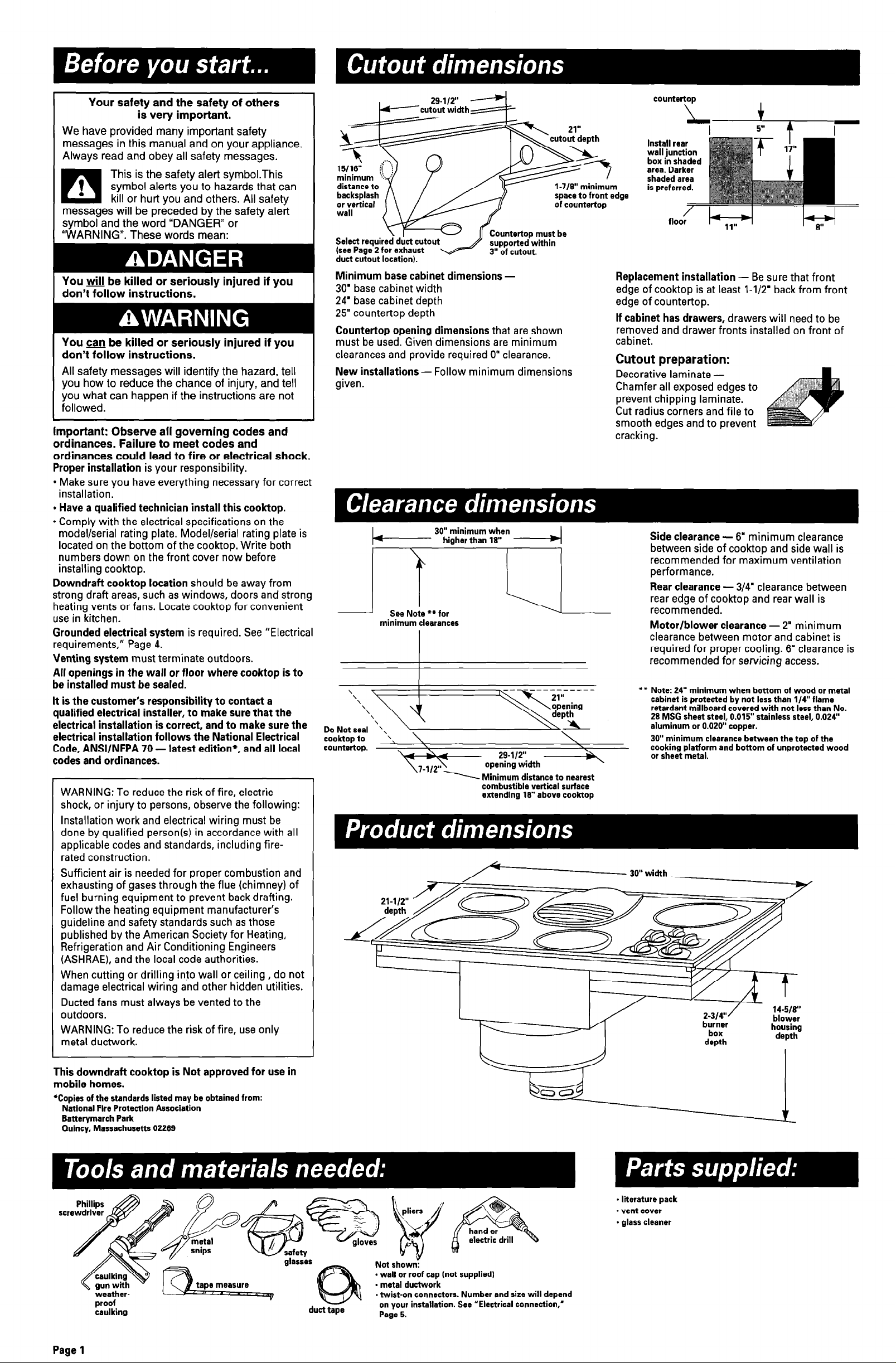
Select required duct cutout
(see Page 2 for exhaust
duct cutout location).
Countertop must be
supported within
Minimum base cabinet dimensions 30’ base cabinet width
24’ base cabinet depth
25” countertop depth
Countertop opening dimensions that are shown
must be used. Given dimensions are minimum
clearances and provide required 0” clearance.
New installations - Follow minimum dimensions
given.
minimum clearances
cooktop to ‘\
countertop.
\
29-112”
opening width
Minimum distance to nearest
combustible vertical surface
extending 18” above cooktop
l-7/8” minimum
space to front edge
of countertop
Replacement installation - Be sure that front
edge of cooktop is at least l-1/2’ back from front
edge of countertop.
If cabinet has drawers, drawers will need to be
removed and drawer fronts installed on front of
cabinet.
Cutout DreDaration:
Decorative laminate Chamfer all exposed edges to
prevent chipping laminate.
Cut radius corners and file to
smooth edges and to prevent
cracking. -
\
area. Darker
. .
Motor/blower clearance - 2” minimum
clearance between motor and cabinet is
required for proper cooling. 6” clearance is
recommended for servicing access.
l l
Note: 24” minimum when bottom of wood or metal
cabinet is protected by not less than l/4” flame
retardant millboard covered with not less than No.
28 MSG sheet steel, 0.015” stainless steel, 0.024’
aluminum or 0.020” copper.
30” minimum clearance between the top of the
cooking platform and bottom of unprotected wood
or sheet metal.
depth
This downdraft cooktop is Not approved for use in
mobile homes.
*Copies of the standards listed may be obtained from:
National Fire Protection Association
Batterymarch Park
Quincy, Massachusetts 02269
SCI
proof
caulking
,
Page 1
W’
duct tape
- literature pack
- vent cover
* glass cleaner
- wall or roof cap (not supplied)
. metal ductwork
- twist-on connectors. Number and size will depend
on your installation. See “Electrical connection,’
Page 5.
Fire Hazard
Venting system MUST terminate to the
outside.
Do Not terminate the ductwork in an attic or
other enclosed space.
Do Not use 4-inch laundry-type wall caps.
Do Not use plastic-type ductwork.
Use only metal ductwork.
Failure to follow these instructions can result
in a fire.
To reduce risk of fire and to properly exhaust air,
be sure to duct air outside.
Do Not vent exhaust air into spaces within walls or
ceilings or into attics, crawl spaces or garages.
Before making cutouts, make sure there is proper
clearance within the wall or floor for the exhaust
duct.
Do Not cut a joist or stud unless absolutely
necessary. If a joist or stud must be cut, then a
supporting frame must be constructed.
Duct materials needed for installation are not
supplied.
Determine which venting method to use. See
“Venting methods,” Page 2.
Next, determine the equivalent duct length using
chart on Page 3. The maximum equivalent duct
length is 60 feet.
The blower housing is set to vent straight out the
back from the cooktop. To vent down, left or right,
see “Preparation,” Page 4.
This downdraft cooktop is rated at 60 feet of
straight duct or the equivalent.
l
If duct length is 10 feet or less, 6” diameter round
ductwork may be used.
l
If duct length is more than 10 feet, use 6”
diameter round or 3-l/4” x IO” rectangular duct.
Thermal breaks: In areas of extreme cold weather, it
may be necessary to provide a short length of
nonmetallic duct as close to the wall as possible to
prevent thermal conduction along the metal duct.
For altitudes above 4,500 ft, reduce recommended
duct run by 20%.
For the most efficient and
quietest operation:
l7J Use 26-gauge minimum galvanized or 25-gauge
minimum aluminum metal duct. Poor-quality
pipe fittings can reduce air flow. (Note: Local
codes may require a heavier-gauge material.)
Flexible metal duct is Not recommended.
iYJ Do Not exhaust more than one downdraft
cooktop into a single duct system.
j7J The length of duct and number of elbows
should be kept to a minimum to provide
efficient performance.
i7J The size of the duct should be uniform.
i7J Use the fewest number of 90” elbows.
i7J Do Not install two elbows together.
q
Make sure there is a minimum of 18’ of straight
duct between the elbows if more than one
elbow is used. (Elbows too close together cause
excess turbulence that reduces air-flow.)
q
Do Not use a 5” elbow in a 6’ or 3-l/4’ x 10”
system.
q
Do Not reduce back to 5” system after using 6”
or 3-l/4” x 10” fittings.
q
Avoid forming handmade crimps. Handmade
crimps may restrict airflow.
i7J Use the recommended duct caps for proper
performance. If an alternate wall or roof cap is
used, be certain cap size is not reduced and that
it has a backdraft damper.
q
Use duct tape to seal all joints in the duct
system.
q
Use caulking to seal exterior wall or roof
opening around the cap.
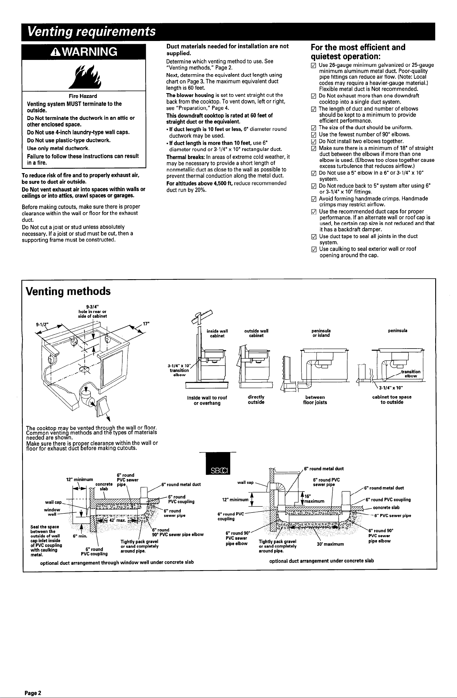
Venting methods
g-314”
hole in rear or
side of cabinet
The cooktop may be vented through the wall or floor.
Common venting methods and the types of materrals
needed are shown.
Make sure there is pro
floor for exhaust duct
er clearance within the wall or
IT
efore makrng cutouts.
inside wall to roof
or overhang
outside wall
cabinet
peninsula
or island
between
floor joists
peninsula
cabinet toe space
to outside
12” minimum
Seal the space
between the
outside of wall
cap inlet inside
of PVC coupling
with caulking
matal.
optional duct arrangement through window well under concrete slab
co;n+;te pipe,
\
6” round
PVC coupling
6” round
PVC sewer
Tightly pick
or sand completely
around pipe.
W6” round metal duct
gravel
PVC sewer
pipe elbow or
Tis’ -.
around pipe..
6” round metal duct
lntly pack gravel
sand completely
optional duct arrangement under concrete slab
\
30’ maximum
” round metal duct
6” round PVC coupling
rvb sewer
-I- - -IL -...
p,pa e)Ioow
Page 2
 Loading...