

KitchenAid KECC568MWW02 Installation Instruction
ELECTRIC COOKTOP INSTALLATION INSTRUCTIONS
INSTRUCTIONS D'INSTALLATION DE LA TABLE DE CUISSON
Table of Contents / Table des matières
COOKTOP SAFETY........................................................1
INSTALLATION INSTRUCTIONS..................................2
Tools and Parts............................................................2
Location Requirements ...............................................2
Electrical Requirements...............................................3
Prepare Cooktop for Installation .................................4
Install Cooktop.............................................................4
Make Electrical Connection.........................................6
Attach Cooktop to Countertop....................................8
Complete Installation...................................................8
COOKTOP SAFETY
Your safety and the safety of others are very important.
We have provided many important safety messages in this manual and on your appliance. Always read and obey all
safety messages.
SÉCURITÉ DE LA TABLE DE CUISSON ................................9
INSTRUCTIONS D’INSTALLATION ........................................9
Outillage et pièces .................................................................9
Exigences d’emplacement ....................................................9
Spécifications électriques....................................................11
Préparation de la table de cuisson pour l'installation ......... 12
Installation de la table de cuisson .......................................12
Raccordement électrique ....................................................14
Fixation de la table de cuisson au plan de travail ............... 16
Achever l'installation............................................................16
This is the safety alert symbol.
This symbol alerts you to potential hazards that can kill or hurt you and others.
All safety messages will follow the safety alert symbol and either the word “DANGER” or
“WARNING.” These words mean:
You can be killed or seriously injured if you don't
immediately follow instructions.
can be killed or seriously injured if you don't
You
follow instructions.
All safety messages will tell you what the potential hazard is, tell you how to reduce the chance of injury, and tell you
what can
happen if the instructions are not followed.
IMPORTANT: Save installation instructions for local electrical inspector’s use.
IMPORTANT : Conserver les instructions d’installation à l’usage de l’inspecteur local des installations électriques.
9759087
INSTALLATION INSTRUCTIONS
Tools and Parts
Gather the required tools and parts before starting installation.
Tools n eeded
■ Tape me a s ure
■ Flat-blade screwdriver
■ Marker or pencil
■ Pliers
■ The cooktop should be installed away from strong draft areas,
such as windows, doors, fans or strong heating vents. The
cooktop should be located for convenient use in the kitchen.
■ Use the countertop opening dimensions that are given with
these Installation Instructions. Given dimensions are minimum
clearances and provide 0" (0 cm) clearance.
■ Grounded electrical supply is required. See “Electrical
Requirements” section.
Parts supplied
■ Clamp brackets (2)
■ 2¹⁄₂" (6.4 cm) clamping screws (2)
Parts needed
■ A UL listed or CSA approved conduit connector
■ UL listed wire nuts
Check local codes. Check existing electrical supply. See
“Electrical Requirements.”
All electrical connections should be made by a licensed, qualified
electrical installer.
Location Requirements
Proper installation is your responsibility. Make sure you have
everything needed for correct installation. It is the responsibility of
the installer to comply with the installation clearances specified in
these instructions.
IMPORTANT: Observe all governing codes and ordinances. When
installing cooktop, use minimum dimensions given.
■ To eliminate the risk of burns or fire by reaching over the
heated surface units, cabinet storage space located above the
surface units should be avoided. If cabinet storage is to be
provided, the risk can be reduced by installing a range hood
that projects horizontally a minimum of 5" (12.7 cm) beyond
the bottom of the cabinets.
■ The cooktop must be a specified cooktop that is approved to
be installed either alone or over an undercounter built-in oven.
Check the cooktop burner box for an approved installation
label. If you do not find this label, contact your dealer to
confirm that your cooktop is approved.
■ Ovens approved for this type of installation will have an
approval label located on the top of the oven. If you do not
find this label, contact your dealer to confirm that your oven is
approved. Refer to oven manufacturer’s Installation
Instructions for approval for built-in undercounter use and
proper cutout dimensions.
■ When installing cooktop over an undercounter built-in oven,
do not fasten cooktop to countertop with clamps. This will
make the cooktop easier to remove if future servicing
becomes necessary.
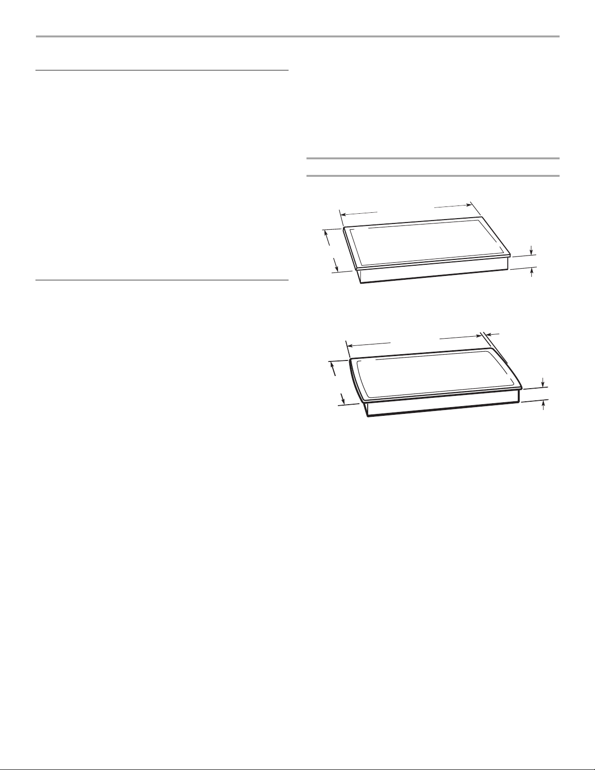
Product Dimensions
Straight-edge cooktop
30" (76.2 cm) or
36" (91.4 cm)
21"
(53.3 cm)
Curved-edge cooktop
⁵⁄₁₆"
21
(54.1 cm)
15" (38.1 cm)
30" (76.2 cm) or
36" (91.4 cm)
³⁄₄" (1.9 cm)
⁷⁄₈"
2
(7.3 cm)
⁷⁄₈"
2
(7.3 cm)
2
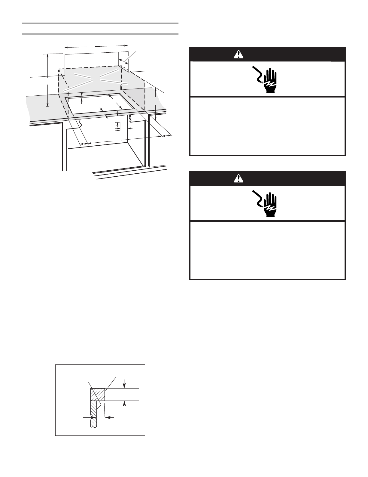
Installation Clearances
Electrical Requirements
For all models except KECC051 series:
A
D
WARNING
C
B
K
F
E
G
H
H
J
A. 15" (38.1 cm) on 15" models; 30" (76.2 cm) on 30" models;
36
" (91.4 cm) on 36" models
B. Combustible area above countertop (shown by dashed box
above)
C. 30
" (76.2 cm) minimum clearance between top of cooktop
platform and bottom of unprotected wood or metal cabinet
" [61 cm] minimum clearance if bottom of wood or metal
(24
cabinet is protected by not less than ¹⁄₄" [0.6 cm] flame
retardant millboard covered with not less than No. 28 MSG
sheet steel, 0.015
cm] aluminum or 0.020" [0.05 cm] copper)
D. 13
" (33 cm) recommended upper cabinet depth
" (5.1 cm)
E. 2
" (52 cm)
F. 20½
G. 18" (45.7 cm) minimum clearance from upper cabinet to
countertop within minimum horizontal clearances to cooktop
H. Junction box or outlet; 12
of countertop; 10" (25.4 cm) from right side of cabinet
I. 14½" (36.6 cm) on 15" models; 29½" (75 cm) on 30" models;
35½" (90.2 cm) on 36" models
J. 1" (2.5 cm) minimum distance to nearest left and right side
combustible surface above cooktop
K. 1½" (3.8 cm) max. counter thickness on 15" models. See
following illustration.
" [0.04 cm] stainless steel, or 0.024" [0.06
" (30.5 cm) minimum from bottom
I
NOTES: After making the countertop cutout, some installations
may require notching down the base cabinet side walls to clear
the burner box. To avoid this modification, use a base cabinet with
sidewalls wider than the cutout.
If cabinet has a drawer, a 3" (7.5 cm) depth clearance from the
countertop to the top of the drawer (or other obstruction) in base
cabinet is required.
For model KECC051 series only:
rear of cabinet or
rear wall under
countertop
back edge
of cutout
B
Electrical Shock Hazard
Disconnect power before servicing.
Use 8 gauge copper wire.
Electrically ground cooktop.
Failure to follow these instructions can result in death,
fire, or electrical shock.
For model KECC051 series only:
WARNING
Electrical Shock Hazard
Disconnect power before servicing.
Use 12 gauge copper wire.
Electrically ground cooktop.
Failure to follow these instructions can result in death,
fire, or electrical shock.
If codes permit and a separate ground wire is used, it is
recommended that a qualified electrical installer determine that
the ground path and wire gauge are in accordance with local
codes.
Do not ground to a gas pipe.
Check with a qualified electrical installer if you are not sure the
cooktop is properly grounded.
Do not have a fuse in the neutral or ground circuit.
■ Make sure that the electrical connection and wire size are
adequate and in conformance with the National Electrical
Code, ANSI/NFPA 70-latest edition or CSA Standards C22.194, Canadian Electrical Code, Part 1 and C22.2 No. O-M91latest edition, and all local codes and ordinances.
A copy of the above code standards can be obtained from:
National Fire Protection Association
Batterymarch Park, Quincy, MA 02269
CSA International
8501 East Pleasant Valley Road
Cleveland, OH 44131-5575
A
A. ¹¹⁄₁₆" (1.7 cm) min.
B. 1½" (3.8 cm) max.
3
Before You Make the Electrical Connection:
B
C
D
E
To properly install your cooktop, you must determine the type of
electrical connection you will be using and follow the instructions
provided for it here.
■ A 4-wire or 3-wire, single phase, 240-volt, 60-Hz., AC-only
electrical supply is required on a separate, 40-amp circuit,
fused on both sides of the line.
NOTE: The KECC051 model series requires a 20-amp circuit.
■ The cooktop should be connected directly to the junction box
through flexible, armored or nonmetallic sheathed, copper
cable. The flexible, armored cable extending from the fuse box
or circuit breaker box should be connected directly to the
junction box.
■ Locate the junction box to allow as much slack as possible
between the junction box and the cooktop so that the cooktop
can be moved if servicing becomes necessary in the future.
■ Do not cut the conduit. Use the length of conduit provided.
■ A UL listed or CSA approved conduit connector must be
provided at each end of the power supply cable (at the
cooktop and at the junction box). A listed conduit connector is
already provided at the cooktop.
■ If the house has aluminum wiring, connect the aluminum
wiring to the copper wire by using special connectors
designed and UL listed for joining copper to aluminum. Follow
the electrical connector manufacturer’s recommended
procedure. Aluminum/copper connection must conform with
local codes and industry accepted wiring practices.
Install Cooktop
Style 1: Cooktop over undercounter built-in oven
IMPORTANT: Clamp brackets should not be used.
1. Turn cooktop right side up.
2. Place cooktop in cutout.
NOTE: Make sure that the front edge of the cooktop is parallel
to the front edge of the countertop. If repositioning is needed,
lift entire cooktop up from cutout to prevent scratching the
countertop.
Style 2: Cooktop over cabinets
1. Determine whether your cabinet construction provides
clearance for installing clamp brackets at burner box ends.
This is the recommended location. Clamp brackets can be
installed on the front and back of burner box bottom, if
necessary.
A
B
Prepare Cooktop for Installation
WARNING
Excessive Weight Hazard
Use two or more people to move and install cooktop.
Failure to do so can result in back or other injury.
1. Decide on the final location for the cooktop. Locate existing
wiring to prevent drilling into or severing wiring during
installation.
2. Using two or more people, place the cooktop upside down on
a protective surface.
3. Remove foam strip from literature packing. Remove backing
from foam strip. Apply foam strip adhesive-side down around
bottom of cooktop, flush with edge.
NOTE: The foam strip protects the underside of the cooktop
glass from debris and helps the cooktop sit flat on uneven
counters.
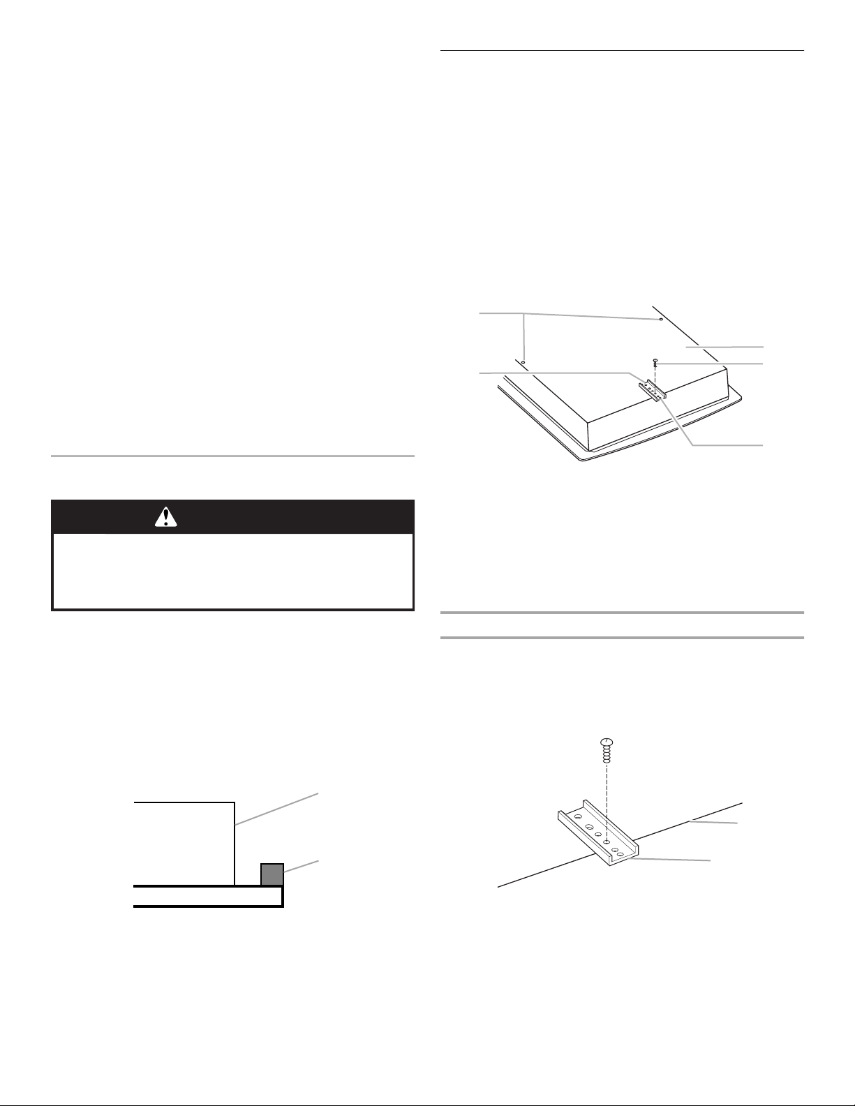
A
A. Attachment screw holes for optional front and back
location.
B. Clamp bracket (end locations recommended)
C. Burner box bottom
D. Attachment screw
E. Attachment screw location (recommended)
2. The clamp brackets can be installed before or after the
cooktop is placed into the cutout. Complete the following
steps for the option you choose.
Installing Brackets Before Placing Cooktop in Cutout
1. Remove the attachment screws for the selected bracket
locations from the bottom of the burner box.
2. Select bracket mounting holes that will allow the bracket to
extend far enough out from the cooktop for the installation of
2½" (6.4 cm) clamping screws. See “Attach Cooktop to
Countertop” for illustration of clamping screw installation.
A
B
A. Edge of burner box bottom
A. Burner box
B. Foam strip
3. Attach brackets to burner box bottom with bracket
attachment screws using the bracket mounting holes selected
in Step 2.
4. Rotate brackets so they do not extend beyond edge of burner
box.
B. Clamp bracket
4
5. Tighten screws just enough to hold brackets in place when
cooktop is put in cutout.
6. Turn the cooktop right side up and place in cutout.
NOTE: Make sure that the front edge of the cooktop is parallel
to the front edge of the countertop. If repositioning is needed,
lift entire cooktop up from cutout to prevent scratching the
countertop.
7. Loosen the screws and rotate the brackets so that they are
perpendicular to the edge of the burner box and extend
beyond its edge. Securely tighten screws.
Installing Brackets After Placing Cooktop in Cutout
1. Place cooktop in cutout.
NOTE: Make sure that the front edge of the cooktop is parallel
to the front edge of the countertop. If repositioning is needed,
lift entire cooktop up from cutout to prevent scratching the
countertop.
2. Remove the attachment screws for the selected bracket
locations from the bottom of the burner box.
3. Select bracket mounting holes that will allow the bracket to
extend far enough out from the cooktop for the installation of
2½" (6.4 cm) clamping screws.
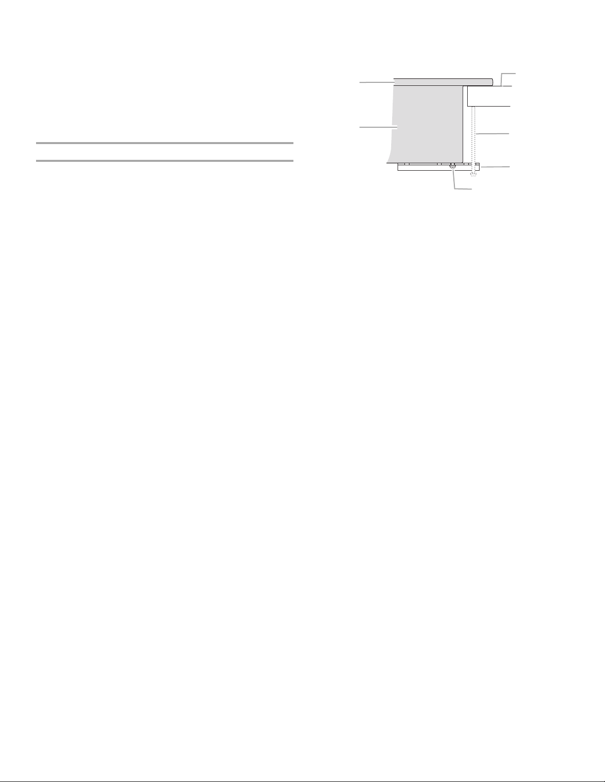
F
A
B
E
D
C
A. Glass cooktop
B. Burner box
C. Attachment screw
D. Clamp bracket (extends far enough beyond
burner box to allow installation of clamping
screws)
E. 2½" (6.4 cm) clamping screw (to be installed in
“Attach Cooktop to Countertop”)
F. Countertop
4. Attach brackets to burner box bottom with bracket
attachment screws using the bracket mounting holes selected
in Step 3. Securely tighten screws.
5
 Loading...