

KitchenAid KECC568GWW2 Installation Instruction
Installation Instructions
IMPORTANT:
Installer: Leave Installation Instructions with the homeowner.
Homeowner: Keep Installation Instructions for future reference.
Save Installation Instructions for local electrical inspector’s use.
Write down the model and serial numbers before installing cooktop.
Both numbers are on the model/serial rating plate, located on the bottom of
the cooktop.
Model # ________________ Serial # _______________
IMPORTANT:
Read and save these
instructions.
Part No.3192799
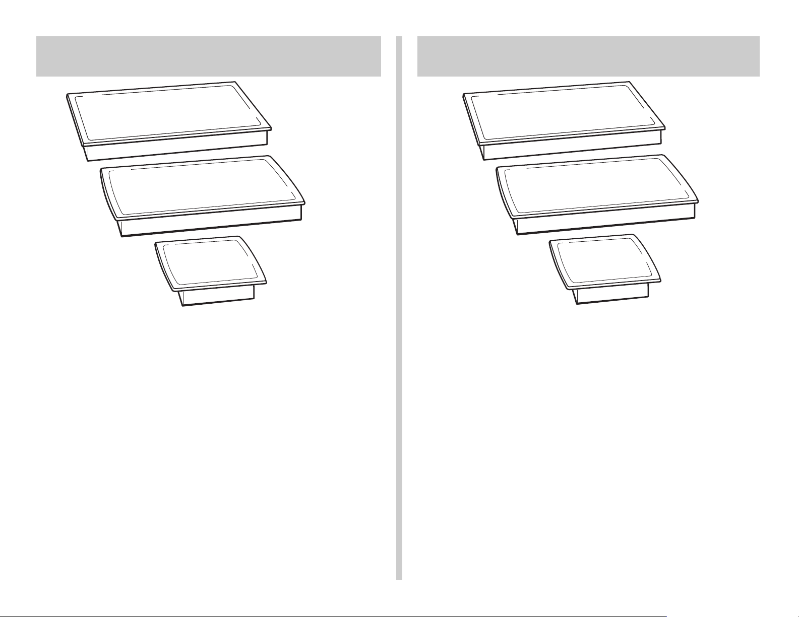
15" (38.1 cm), 30" (76.2 cm) and
36" (91.4 cm) Electric Built-in
Ceramic Cooktops
Instructions d’installation
IMPORTANT :
Installateur : Remettre les instructions d’installation au propr iétaire.
Propriétaire : Conserver les instructions d’installation pour référence
ultérieure.
Conserver les instr uctions d’installation pour utilisation par l’inspecteur local
des installations électriques.
Inscrire les numéros de modèle et de série avant d’installer la surface de
cuisson.
Les deux numéros sont indiqués sur la plaque signalétique des numéros de
modèle et de série, située au fond de la table de cuisson.
N° de modèle ______________ N° de série _____________
Tables de cuisson électriques
encastrées en céramique de 38,1 (15 po),
de 76,2 cm (30 po) et de 91,4 cm (36 po)
Pièce n° 3192799
IMPORTANT :
Lire et conserver
ces instructions.
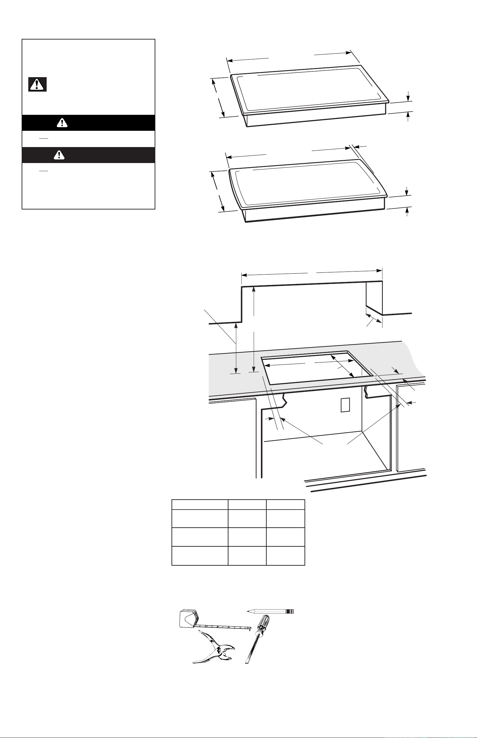
Panel A
36" (91.4 cm) or 30" (76.2 cm) min. base
cabinet is required. If cabinet has a drawer, a
3" (7.5 cm) depth clearance from the countertop
to the top of the drawer (or other obstruction) in
the base cabinet is required.
Before you star t... Product dimensions
Cutout dimensions/requirements
Junction box,
12" (30.5 cm)
or more above
floor and 10"
(25.4 cm) from
right side of
cabinet.
Copies of the standards listed may be obtained from:
** National Fire Protection Association
Batterymarch Park
Quincy, Massachusetts 02269
*** Canadian Standard Association
178 Rexdale Boulevard
Etobicoke, (Toronto), Ontario M9W 1R3
Your safety and the safety of others
is very important.
We have provided many important safety messages
in this manual and on your appliance. Always read
and obey all safety messages.
This is the safety alert symbol. This symbol
alerts you to hazards that can kill or hurt
you and others. All safety messages will be
preceded by the safety alert symbol and the word
“DANGER” or “WARNING”. These words mean:
All safety messages will identify the hazard, tell you
how to reduce the chance of injury, and tell you
what can happen if the instructions are not
followed.
You will be killed or seriously injured if you don’t
follow instructions.
You can be killed or seriously injured if you don’t
follow instructions.
WARNING
D ANGER
Proper installation is your responsibility. Make
sure you have everything for correct installation.
It is the responsibility of the installer to comply
with the installation clearances specified in these
instructions.
Cooktop installed over oven installation: Only
certain specified cooktop and oven models are
approved for cooktop over oven installations.
Cooktops approved for this type of installation
will have an approval label located on the outside
of the burner box. If you do not find this label,
contact your dealer to confirm that cooktop is
approved.The label on the bottom of your
cooktop lists the cooktop and oven combinations
that are approved for this type of installation.
Ovens approved for this type of installation will
have an approval label located on top of oven. If
you do not find this label, contact dealer to
confirm that oven is approved.Refer to oven
manufacturer’s Installation Instr uctions for
approval for built-under use and proper cutout
dimensions.
When installing cooktop over a built-under
oven, Do Not fasten cooktop to countertop with
clamps. Cooktop then will be easy to remove if
servicing is ever necessary.
Check location where cooktop will be installed.
The location should be away from strong draft
areas, such as windows, doors and strong
heating vents or fans.The cooktop should be
located for convenient use in the kitchen.
Grounded electrical supply is required. See
“Electrical requirements,” Panel B.
Important:
Observe all governing codes and ordinances.
Failure to meet governing codes and
ordinances could lead to fire or electrical
shock.
When installing a cooktop under existing
cabinets and the installation does not meet the
minimum cabinet clearances.Install a range
hood above the cooktop to avoid burn hazards.
Countertop opening dimensions that are
shown must be used. Given dimensions are
minimum clearances and provide required 0"
(0 cm) clearance.
New installations — follow minimum
dimensions given.
Replacement installations — Be sure that
front edge of cooktop is at least 1-1/2"
(3.8 cm) back from front edge of countertop.
It is the customer’s responsibility:
To contact a qualified electrical installer.
To assure that the electrical installation is
adequate and in conformance with National
Electrical Code, ANSI/NFPA 70 — latest
edition**, or CSA Standards
C22.1-94, Canadian Electrical Code, Part 1
and C22.2 No. 0-M91 - latest edition *** and all
local codes and ordinances.
2-7/8" (7.3 cm)
burner box
height
21" (53.3 cm) depth
21-5/16" (54.1 cm) depth
30" (76.2 cm) or
36" (91.4 cm) width
15" (38.1 cm)
30" (76.2 cm) or
36" (91.4 cm) width
3/4" (1.9 cm)
both sides
2-3/4" (7.3 cm)
burner box
height
20-1/2"
(52 cm)
18" (45.7 cm) min.
clearance upper
cabinet to countertop
within minimum
clearances to cooktop
Do not seal
cooktop to
countertop.
2" min.
(5.1 cm)
13" (33 cm)
recommended
upper cabinet
depth
Cooktop width A B
15" 14-1/2" 15"
(38.1 cm) (36.6 cm) (38.1 cm)
30" 29-1/2" 30"
(76.2 cm) (75 cm) (76.2 cm)
36" 35-1/2" 36"
(91.4 cm) (90.2 cm) (91.4 cm)
1" (2.5 cm) min. distance to
nearest left and right side
combustible surface above
cooktop.
See NOTE*
for minimum
clearances.
*
Note: 24" (61 cm) min.
clearance if bottom of wood or
metal cabinet is protected by
not less than 1/4" (0.6 cm)
flame retardant millboard
covered with not less than No.
28 MSG sheet steel, 0.015"
(0.04 cm) stainless steel, or
0.024"(0.06 cm) aluminum or
0.020" (0.05 cm) copper.
30" (76.2 cm) min. clearance
between top of cooking
platform and bottom of
unprotected wood or metal
cabinet.
Tools needed for installation:
flat-blade
screwdriver
pencil
pliers
ruler or
tape measure
Panel B
Electrical requirements
If codes permit and a separate ground wire is
used, it is recommended that a qualified
electrician determine that the ground path is
adequate.
Do Not ground to a gas pipe.
Check with a qualified electrician if you are
not sure the cooktop is properly grounded.
Do Not have a fuse in the neutral or ground
circuit.
IMPORTANT:
Save Installation Instructions for electrical
inspector’s use.
A.A three-wire or four-wire, single phase,
240-volt, 60-Hz, AC-only electrical supply is
required on a separate, 40-ampere circuit, (Note:
The KECC051 series requires a 20-ampere
circuit), fused on both sides of the line. A timedelay fuse or circuit breaker is recommended.
The fuse size must not exceed the circuit rating
of the appliance specified on the model/serial
rating plate located on the bottom of the cooktop.
B.THE COOKTOP MUST BE
CONNECTED WITH COPPER WIRE ONLY.
C.Wire sizes and connections must conform
to the requirements of the National Electrical
Code ANSI/NFPA 70 – latest edition **, or CSA
Standards C22.1-94, Canadian Electrical Code,
Part 1 and C22.2 No.0-M91 - latest edition ***
and all local codes and ordinances.
D.The cooktop should be connected directly
to the fused disconnect or circuit breaker box
through flexible, armored or non-metallic
sheathed, copper cable.The flexible, armored
cable extending from the fuse box or circuit
breaker box should be connected directly to the
junction box.
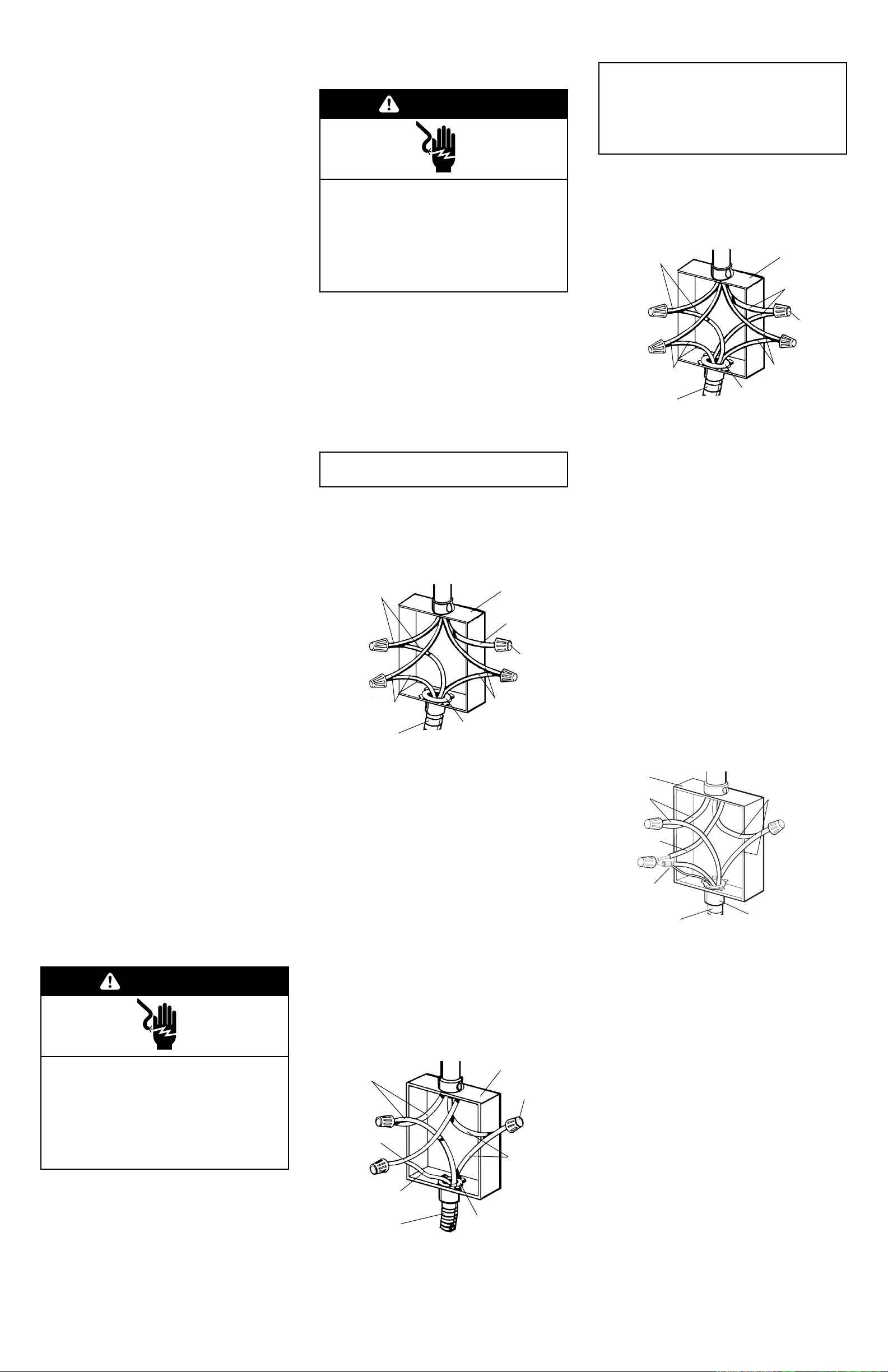
1. Follow steps 1 and 2 from “A” above.
2. Connect the bare cooktop wire with the white
wire; the two red wires together; and the two
black wires together using twist-on connectors.
(See Figure 2.)
A.Where local codes Do Not permit
connecting the frame-ground conductor to
the neutral (white) junction box wire. (Used
for Canadian installations):
3-wire cable from power supply
junction box
black wires
twist-on
connectors
U.L.- or C.S.A.- listed
conduit connector
3-wire cable from cooktop
bare ground wire
white wire
red wires
1. Disconnect power supply.
2. Connect the flexible, armored cable from the
cooktop to the junction box using a U.L.- or
C.S.A.-listed conduit connector. Tighten screws
on conduit connector.
3. Connect the two black wires together; then
connect the two red wires together using twiston connector.(See Figure 1.)
4. Connect the green or bare ground wire from
the cooktop cable to the grounded wire in the
junction box or other grounded connector
using twist-on connector.
5. Put a twist-on connector on end of white wire.
Do Not connect bare ground wire to neutral
(white) wire in junction box.
junction box
4-wire cable from power supply
twist-on
connector
black wires
U.L.- or C.S.A.- listed
conduit connector
3-wire cable from cooktop
bare or green
ground wires
white wire
red wires
Figure 1
Grounded neutral
Figure 2
Ungrounded neutral
For all models except KECC051 series:
B.Where local codes permit connecting
the frame-ground conductor to the neutral
(white) junction box wire. (Not used for
Canadian installations):
F. A U.L.- or C.S.A.-listed conduit connector
must be provided at each end of the power
supply cable (at the cooktop and at the junction
box).
E.Locate the junction box to allow as much
slack as possible between the junction box and
the cooktop so that the cooktop can be moved if
servicing is ever necessary. Do Not cut the
conduit.
This cooktop must be connected to a
grounded, metallic permanent wiring system
or a ground connector should be connected
to the ground terminal or wire lead on the
cooktop.
This cooktop is manufactured with a frame
connected, green or bare ground wire.Connect
the cooktop cable to the junction box through the
U.L.- or C.S.A.-listed conduit connector.
Complete electrical connection according to local
codes and ordinances.
WARNING
Copies of the standards listed may be obtained from:
** National Fire Protection Association
Batterymarch Park
Quincy, Massachusetts 02269
*** Canadian Standard Association
178 Rexdale Boulevard
Etobicoke (Toronto), Ontario M9W 1R3
Electrical Shock Hazard
Turn power supply off before connecting
wires.
Use 8-gauge solid copper wire.
Electrically ground cooktop.
Failure to follow these instructions can
result in death, fire, or electrical shock.
Electrical connection
For model KECC051 series only:
WARNING
Electrical Shock Hazard
Turn power supply off before connecting
wires.
Use 12-gauge solid copper wire.
Electrically ground cooktop.
Failure to follow these instructions can
result in death, fire, or electrical shock.
This cooktop must be connected to a
grounded, metallic permanent wiring system or
a ground connector should be connected to the
ground terminal or wire lead on the cooktop.
This cooktop is manufactured with a frame
connected, green or bare ground wire.Connect
the cooktop cable to the junction box through the
U.L.- or C.S.A.-listed conduit connector.
Complete electrical connection according to local
codes and ordinances.
For all cooktop models with threewire cable from the cooktop:
A.Where local codes Do Not permit
connecting the frame-ground conductor to
the neutral (white) junction box wire: (Used
for Canadian installations):
1. Disconnect power supply.
2. Connect the flexible, armored cable from the
cooktop to the junction box using a U.L.- or
C.S.A.-listed conduit connector. Tighten screws
on conduit connector.
3. Connect the two black wires together; then
connect the two red wires together using twiston connectors. (See Figure 3.)
4. Separate the factory-crimped bare and white
cooktop cable wires.
5. Connect the two white wires together using
twist-on connectors.
6. Connect the bare ground wire from the
cooktop cable to the grounded wire in the
junction box or other grounded connector
using twist-on connector.(See Figure 3.)
Do Not connect bare ground wire to neutral
(white) wire in junction box.
junction box
4-wire cable from power supply
twist-on
connector
black wires
U.L.- or C.S.A.- listed
conduit connector
4-wire cable from cooktop
bare or green
wires
white wires
red wires
Figure 3
Ungrounded neutral
Figure 4
Grounded neutral
B.Where local codes permit connecting
the frame-ground conductor to the neutral
(white) junction box wire. (Not used for
Canadian installations):
1. Follow steps 1 and 2 from “A” above.
2. Connect the two black wires together; the two
red wires together; and the factory-crimped
bare and white cooktop cable wires to the
white (neutral) wire in the junction box using
twist-on connectors. (See Figure 4.)
For all cooktop models with four-wire
cable from the cooktop. (These
cooktops are manufactured with white
(neutral) power supply wire and a
cabinet-connected bare ground wire
factory-crimped together.):
junction
box
red
wires
white
wire
white and bare
grounding oven cable
wires — factory crimped
3-wire cable from
power supply
black
wires
4-wire cable from cooktop
U.L.- or C.S.A.- listed
conduit connector
C.Where local codes Do Not permit
connecting the frame-ground conductor to
the neutral (white) junction box wire:
1. Follow steps 1 and 2 from “A” above.
2. Connect the two black wires together and the
two red wires together.
3. Separate the factory-crimped bare and white
cooktop cable wires.
4. Connect the two white wires together using
twist-on connectors.
5. Connect the bare ground wire from the
cooktop cable to a grounded wire in the
junction box or other grounded connector
using twist-on connector.(See Figure 3.)
Do Not connect bare ground wire to neutral
(white) wire in junction box.
 Loading...