

KitchenAid KECC568GWW3, KECC568GWH3, KECC568GWH0, KECC568GSS3, KECC568GBT1 Installation Guide
...
Piece n° 3191771 Rev. A
Part No. 3191771Rev. A
Tables de cuisson 61ectriques
encastr s en c6ramique
de 76,2 cm pc) et de
9t,4 cm (36 pc}
IMPORTANT:
Life et conserver
ces instructions,
iMPORTANT :
Jnstallateur : Remettre les instructions d'instalJation au
proprietaire.
Propri_taire : Conserver les instructions d'instalJation pour
ref@ence ult@ieure.
Conserver les instructions d'installation pour utilisation par
l'inspecteur IocaJ des instaJJations electriques.
Inscrire les num@os de modele et de s@ie avant d'instalJer la
surface de cuisson.
Les deux num@os sont indiques sur la plaque signaletique des
num@os de modele et de s@ie, situee au fond de la table de
cuisson.
N° de modele N° de s@ie
30 '° (76.2 cm) and 36 '°
(91.4 cm) Electric Built-in
Ceramic Cooktops
Read and save these
instructions,
iMPORTANT:
installer: Leave JnstaJlation Instructions with the homeowner.
Homeowner: Keep InstaJlation instructions for future reference.
Save JnstalJation instructions for local electrical inspector's use.
Write down the model and serial numbers before installing cooktop.
Both numbers are on the model/serial rating plate, located on the
bottom of the cooktop.
Model # Serial #
Before you start...
Your safety and the safety of others
isvery important.
We haveprovided many important safety messages
in this manualandon your appliance.Always read
and obey all safety messages.
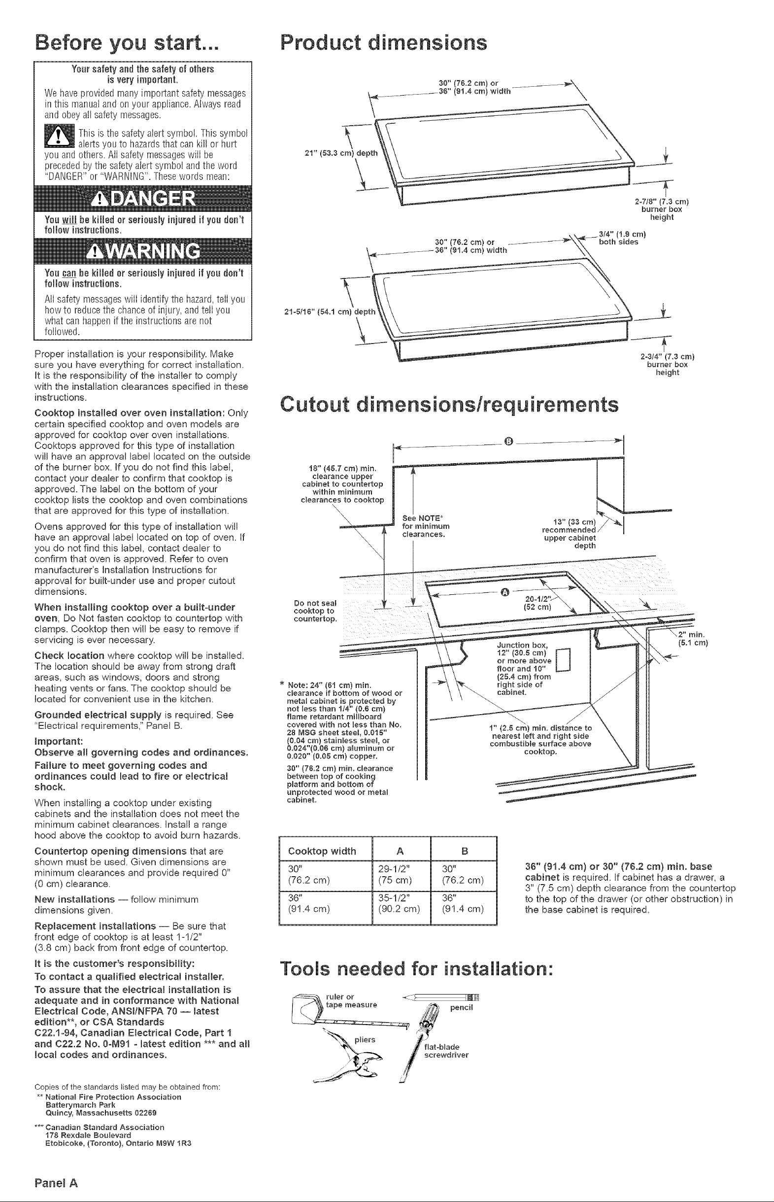
Product dimensions
30" (7&2 cra} or ..........
.___-36" (gl.4 cra} width
X
This is the safety alert symbol. This symb01
alerts you to hazardsthat can kill or hurt
you and others. Aii safety messageswili be
precededby the safety alert symbol andthe word
"DANGER"or "WARNING"=Thesewords mean:
Youca_ be killed or seriously injuredif you don't
f0H0w instructions.
All safety messageswill identify the hazard,teii you
how to reducethe chance of injury, and teli you
what can happenif the instructions are not
followed.
Proper installation is your responsibility. Make
sure you have everything for correct installation.
it is the responsibility of the installer to comply
with the installation clearances specified in these
instructions.
Cooktop installed over oven installation: Only
certain specified cooktop and oven models are
approved for cooktop over oven installations.
Cooktops approved for this type of installation
will have an approval label located on the outside
of the burner box. if you do not find this label,
contact your dealer to confirm that cooktop is
approved. The label on the bottom of your
cooktop lists the cooktop and oven combinations
that are approved for this type of installation.
Ovens approved for this type of installation will
have an approval label located on top of oven. if
you do not find this label, contact dealer to
confirm that oven is approved. Refer to oven
manufacturer's installation instructions for
approval for built-under use and proper cutout
dimensions.
When installing cooktop over a built-under
oven, Do Not fasten cooktop to countertop with
clamps. Cooktop then will be easy to remove if
servicing is ever necessary.
Check location where cooktop will be installed.
The location should be away from strong draft
areas, such as windows, doors and strong
heating vents or fans. The cooktop should be
located for convenient use in the kitchen.
Grounded electrical supply is required. See
"Electrical requirements," Panel B.
Jraportant:
Observe all governing codes and ordinances.
Failure to meet governing codes and
ordinances could lead to fire or electrical
shock.
When installing a cooktop under existing
cabinets and the installation does not meet the
minimum cabinet clearances. Install a range
hood above the cooktop to avoid burn hazards.
Countertop opening diraensions that are
shown must be used. Given dimensions are
minimum clearances and provide required 0"
(0 cm) clearance.
New installations -- follow minimum
dimensions given.
RepJaceraent installations -- Be sure that
front edge of cooktop is at least 1-1/2"
(3.8 cm) back from front edge of countertop.
Jt is the customer's responsibility:
To contact a qualified electrical installer.
To assure that the electrical installation is
adequate and in conforraance with National
Electrical Code, ANSItNFPA 70 -- latest
edition**, or CSA Standards
C22.1-94, Canadian Electrical Code, Part 1
and 022.2 No. O-[W91- latest edition *** and all
local codes and ordinances.
\
21" (83,3 era} depth
30" (76.2 era) or
........... 36" (91.4 cra) width
21o5/16" (54.t era) depth
Cutout dimensionstrequirements
18" (4S,7 cra) rain.
dearance upper
cabinet to countertop
within minimum
clearances to cooktop
\,
\
clearances, upper cabinet
@
Do not seal
cooktop to
countertop.
Junction bow
12" (3O.S era) [_
or more above
floor and 10"
* Note: 24" (el cra) rain.
clearance if bottom of wood or
raetal cabinet is protected by
not less than 114" (O.Oera}
flame retardant raHIboard
covered with not Jess than No.
28 MeG sheet steet, 0.015"
(0.04 era} stainless steel, or
0.024"(0.08 cra) alurainura or
0.020" (O.OS cra) copper.
30" (7&2 cra) rain. c{earance
between top of cooking
platforra and bottom of
unprotected wood or raetal
cabinet.
(25.4 era) from
right side of
cabinet.
1" (2.5 cra) rain. distance to
nearest _eft and right side
eorabustibie surface above
Cooktop width A B
30" 29=1/2" 30"
(76.2 cm) (75 cm) (76.2 cm)
36" 35-1/2" 36"
(91.4 cm) (90.2 cm) (91.4 cm)
Tools needed for installation:
recoraraenaeo / I
20o1/2';
($2cra)
LJ
eooktop.
36" (91,4 cra) or 30" (76.2 cra) rain. base
cabinet is required. Jfcabinet has a drawer, a
3" (7.5 cm) depth clearance from the countertop
to the top of the drawer (or other obstruction) in
the base cabinet is required.
Y
depth
both sides
2W/8" (7.3 cra)
burner box
height
-----T
2=314" (7.3 cra)
burner box
height
Copies of the standards listed may be obtained from:
** National Fire Protection Association
Batteryraareh Park
Quincy, Massachusetts 02269
*** Canadian Standard Association
178 Rexda_e Boulevard
Etobicoke, (Toronto), Ontario Mew tR3
Panel A
Electrical requirements
if codes permit and a separate ground wire is
used, it is recommended that a qualified
electrician determine that the ground path is
adequate.
Do Not ground to a gas pipe.
Check with a qualified electrician if you are
not sure the cooktop is properly grounded.
Do Not have a fuse in the neutrat or ground
circuit.
iMPORTANT:
Save _nstaliat{on instructions for electrical
inspector's use.
A E A three-wire or four=wire, single phase,
240=volt, 60=Hz, AC=only electrical supply is
required on a separate, 40=ampere circuit, fused
on both sides of the line. A time=delay fuse or
circuit breaker is recommended. The fuse size
must not exceed the circuit rating of the
appliance specified on the model/serial rating
plate located on the bottom of the cooktop.
mTHE COOKTOP MUST BE
CONNECTED WiTH COPPER WiRE ONLY
C E Wire sizes and connections must conform
to the requirements of the National Electrical
Code ANSJ/NFRA 70 = latest edition **, or CSA
Standards C22.1=94, Canadian Electrical Code,
Part 1 and C22.2 No. 0=M91 =latest edition ***
and aHlocal codes and ordinances.
E The cooktop should be connected directly
to the fused disconnect or circuit breaker box
through flexible, armored or non=metallic
sheathed, copper cable. The flexible, armored
cable extending from the fuse box or circuit
breaker box should be connected directly to the
junction box.
Electrical connection
Electrical Shock Hazard
Turn power supply off before connecting
wires.
Use 8-gauge solid copper wire.
Electrically ground cooktop.
Failure to follow these instructions can
result in death, fire, or electrical shock.
This cooktop must be connected to a
grounded, metallic permanent wiring system
or a ground connector should be connected
to the ground terminat or wire lead on the
cooktop.
This cooktop is manufactured with a frame
connected, green or bare ground wire. Connect
the cooktop cable to the junction box through the
U.L= or C.S.A.=iisted conduit connector.
Complete electrical connection according to local
codes and ordinances.
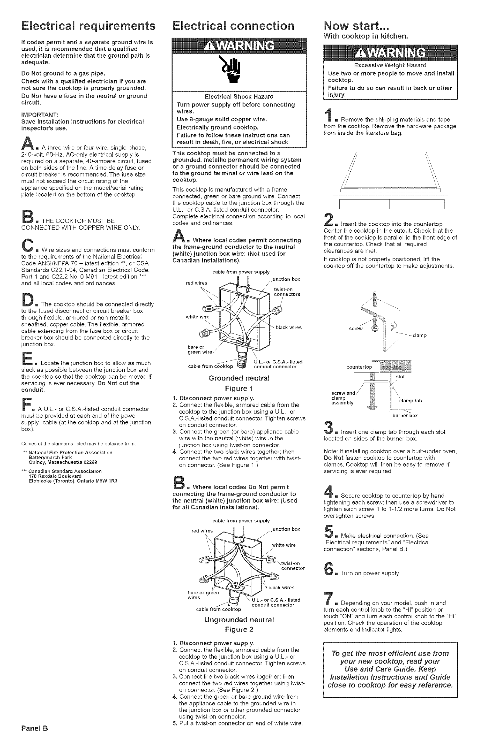
AR Where local codes permit connecting
the frame=ground conductor to the neutral
(white} junction box wire: (Not used for
Canadian installations).
cable from power supply
"unction box
twist-on
red wires
connectors
black wires
Now start...
With cooktop in kitchen.
Excessive Weight Hazard
Use two or more people to move and instal[
cooktop.
Failure to do so can result in back or other
injury.
m Remove the shipping materials and tape
from the cooktop. Remove the hardware package
from inside the literature bag=
m Insert the cooktop into the countertop.
Center the cooktop in the cutout. Check that the
front of the cooktop is parallel to the front edge of
the countertop. Check that all required
clearances are met.
If cooktop is not properly positioned, lift the
cooktop off the countertop to make adjustments.
E m Locate the junction box to allow as much
slack as possible between the junction box and
the cooktop so that the cooktop can be moved if
servicing is ever necessary. Do Not cut the
conduit.
Fm A U.L.= or C.S.A.=listed conduit connector
must be provided at each end of the power
supply cabJe (at the cooktop and at the junction
box).
Copies of the standards listed may be obtained from:
** National Fire Protection Association
Batterymarch Park
Quincy, Massachusetts 02269
*** Canadian Standard Association
178 Rexda[e Boulevard
atobicoke (Toronto), Ontario MgW 1R3
U.L- or C.S.A.- Hsted
conduit connector
Grounded neutral
Figure 1
1. Disconnect power supply.
2. Connect the flexible, armored cable from the
cooktop to the junction box using a U.L= or
C.S.A.=[isted conduit connector. Tighten screws
on conduit connector.
3. Connect the green (or bare) appliance cable
wire with the neutral (white) wire in the
junction box using twist=on connector.
4. Connect the two black wires together; then
connect the two red wires together with twist=
on connector. (See Figure 1.)
m Where [ocat codes Do Not permit
connecting the frame=ground conductor to
the neutral (white} junction box wire: (Used
for all Canadian installations}.
cable from power supp}y
_ junction box
i _hite wire
countertop
slot
/
screw
damp
assembly damp tab
burner box
3E Insert one clamp tab through each slot
located on sides of the burner box.
Note: [f installing cooktop over a built=under oven,
Do Not fasten cooktop to countertop with
cramps. Cooktop will then be easy to remove if
servicing is ever required.
4m Secure cooktop to countertop by hand=
tightening each screw; then use a screwdriver to
tighten each screw 1 to 1=1/2 more turns. Do Not
overtighten screws.
5m Make electrical connection. (See
"Electrical requirements" and "Electrical
connection" sections, Panel B.)
Pane[ B
red
connector
t I _'-,twist-on
bare or green _
w_res
cable from cooktop
Ungrounded neutral
Figure 2
1. Disconnect power supply.
2. Connect the flexible, armored cable from the
cooktop to the junction box using a U.L= or
C.S.AMisted conduit connector. Tighten screws
on conduit connector.
3. Connect the two black wires together; then
connect the two red wires together using twist=
on connector. (See Figure 2.)
4. Connect the green or bare ground wire from
the appliance cable to the grounded wire in
the junction box or other grounded connector
using twist=on connector.
5. Put a twist=on connector on end of white wire.
,,J_, black wires
U.L.= or C.S.A.- listed
conduit connector
Turn on power supply.
7=_ Depending on your model, push in and
turn each control knob to the "Hi" position or
touch "ON" and turn each control knob to the "HI"
position. Check the operation of the cooktop
elements and indicator lights.
To get the most efficient use from
your new cooktop, read your
Use and Care Guide. Keep
Installation instructions and Guide
close to cooktop for easy reference.
 Loading...