

KitchenAid KECC051HWH0, KECC568GWH2, KECC568GBT2, KECC568GBL2, KECC568GAL2 Installation Guide
...
Piece n° 3192799
Part No. 3192799
Tables de cuisson _lectriques
encastr_es en c_ramique de 38,1 (15 po),
de 76,2 cm (30 po) et de 91,4 cm (36 po)
IMPORTANT:
L=reet conserver
ces instructions.
IMPORTANT :
Installateur : Remettre les instructions d'installation au proprietaire.
Propri_taire : Conserver les instructions d'installation pour reference
ulterieure.
Conserver les instructions d'installation pour utilisation par I'inspecteur local
des installations electriques.
Inscrire les numeros de modele et de serie avant d'installer la surface de
cuisson.
Les deux numeros sont indiques sur la plaque signaletique des numeros de
modele et de serie, situee au fond de la table de cuisson.
N° de modele N° de serie
15" (38.1 cm), 30" (76.2 cm) and
36" (91..4 cm) Electric Built-in
Ceram=c Cooktops
IMPORTANT:
Read and save these
instructions.
IMPORTANT:
Installer: Leave Installation Instructions with the homeowner.
Homeowner: Keep Installation Instructions for future reference.
Save Installation Instructions for local electrical inspector's use.
Write down the model and serial numbers before installing cooktop.
Both numbers are on the model/serial rating plate, located on the bottom of
the cooktop.
Model # Serial #

Before you start...
Yoursafety and the safety of others
isvery important.
We haveprovided many important safety messages
in this manualandon your appliance,Always read
and obey all safety messages,
This is the safetyalert symbol. This symb01
alerts you to hazardsthatcan kill or hurt
you and others, Ati safety messageswiii be
precededby the safety aiert symbol andthe word
"DANGER"or "WARNING", Thesewords mean:
Product dimensions
30" (76.2 cm) or
_36" (91.4 cm) width
21" (63.3 cm) depth
2-7/8" (7.3 cm)
burner box
height
Youca_ be killed or seri0usly injuredif you don't
f0110winstructi0ns.
AIi safety messageswiii identify the hazard,teii you
how to reducethe chance of injury, andteli you
what can happenif the instructions arenot
followed.
Proper installation is your responsibility. Make
sure you have everything for correct installation.
It is the responsibility of the installer to comply
with the installation clearances specified in these
instructions.
Cooktop installed over oven installation: Only
certain specified cooktop and oven models are
approved for cooktop over oven installations.
Cooktops approved for this type of installation
will have an approval label located on the outside
of the burner box. If you do not find this label,
contact your dealer to confirm that cooktop is
approved. The label on the bottom of your
cooktop lists the cooktop and oven combinations
that are approved for this type of installation.
Ovens approved for this type of installation will
have an approval label located on top of oven. If
you do not find this label, contact dealer to
confirm that oven is approved. Refer to oven
manufacturer's Installation Instructions for
approval for built-under use and proper cutout
dimensions.
When installing cooktop over a built-under
oven, Do Not fasten cooktop to countertop with
clamps. Cooktop then will be easy to remove if
servicing is ever necessary.
Check location where cooktop will be installed.
The location should be away from strong draft
areas, such as windows, doors and strong
heating vents or fans. The cooktop should be
located for convenient use in the kitchen.
Grounded electrical supply is required. See
"Electrical requirements," Panel B.
Important:
Observe all governing codes and ordinances.
Failure to meet governing codes and
ordinances could lead to fire or electrical
shock.
When installing a cooktop under existing
cabinets and the installation does not meet the
minimum cabinet clearances. Install a range
hood above the cooktop to avoid burn hazards.
Countertop opening dimensions that are
shown must be used. Given dimensions are
minimum clearances and provide required 0"
(0 cm) clearance.
New installations -- follow minimum
dimensions given.
Replacement installations -- Be sure that
front edge of cooktop is at least 1-1/2"
(3.8 cm) back from front edge of countertop.
It is the customer's responsibility:
To contact a qualified electrical installer.
To assure that the electrical installation is
adequate and in conformance with National
Electrical Code, ANSI/NFPA 70 -- latest
edition**, or CSA Standards
C22.1-94, Canadian Electrical Code, Part 1
and C22.2 No. 0-M91 - latest edition *** and all
local codes and ordinances.
15" (38.1 cm)
30" (76.2 cm) or
(91.4 cm) width
21-5/16" (54.1 cm) depth
Cutout dimensions/requirements
18" (46.7 cm) min.
clearance upper
cabinet to countertop
within minimum
clearances to cooktop
\,
\
Do not seal
cooktop to
countertop.
Junction box,
12" (30,5 cm) ['_
or more above
floor and 10"
(25.4 cm) from
Note: 24" (61 cm) rain.
clearance if bottom of wood or
metal cabinet is protected by
not less than t14" (0.6 cm)
flame retardant mHIboard
covered with not less than No.
28 MSG sheet steel, 0.015"
(0.04 cm} stainless steel, or
0.024"(0.00 cm) aluminum or
0.020" (0.05 cm} copper.
30" (70.2 cm) rain. clearance
between top of cooking
platform and bottom of
unprotected wood or metal
cabinet.
right side of
cabinet.
1" (2.5 cm) rain. distance to
nearest left and right side
combustible surface above
cooktop.
Cooktop width A B
15" 14-1/2" 15"
(38.1 cm) (36.6 cm) (38.1 cm)
30" 29-1/2" 30"
(76.2 cm) (75 cm) (76.2 cm)
36" (91.4 cm) or 30" (76.2 cm) min. base
cabinet is required. If cabinet has a drawer, a
3" (7.5 cm) depth clearance from the countertop
36" 35-1/2" 36"
(91.4 cm) (90.2 cm) (91.4 cm)
to the top of the drawer (or other obstruction) in
the base cabinet is required.
Tools needed for installation:
LJ
both sides
2-3/4" (7.3 cm)
burner box
height
(5.1 cm)
Copies of the standards listed may be obtained from:
** National Fire Protection Association
Batterymarch Park
Quincy, Massachusetts 02269
*** Canadian Standard Association
178 Rexdale Boulevard
Etobicoke, (Toronto), Ontario Mgw 1R3
Panel A
Electrical requirements
If codes permit and a separate ground wire is
used, it is recommended that a qualified
electrician determine that the ground path is
adequate.
Do Not ground to a gas pipe.
Check with a qualified electrician if you are
not sure the cooktop is properly grounded.
Do Not have a fuse in the neutral or ground
circuit.
IMPORTANT:
Save Installation Instructions for electrical
inspector's use.
A= A three-wire or four-wire, single phase,
240-volt, 60-Hz, AC-only electrical supply is
required on a separate, 40-ampere circuit, (Note:
The KECC051 series requires a 20-ampere
circuit), fused on both sides of the line. A time-
delay fuse or circuit breaker is recommended.
The fuse size must not exceed the circuit rating
of the appliance specified on the model/serial
rating plate located on the bottom of the cooktop.
B m THE COOKTOP MUST BE
CONNECTED WITH COPPER WIRE ONLY.
C= Wire sizes and connections must conform
to the requirements of the National Electrical
Code ANSI/NFPA 70 - latest edition **, or CSA
Standards C22.1-94, Canadian Electrical Code,
Part 1 and C22.2 No. 0-M91 - latest edition ***
and all local codes and ordinances.
D m The cooktop should be connected directly
to the fused disconnect or circuit breaker box
through flexible, armored or non-metallic
sheathed, copper cable. The flexible, armored
cable extending from the fuse box or circuit
breaker box should be connected directly to the
junction box.
E= Locate the junction box to allow as much
slack as possible between the junction box and
the cooktop so that the cooktop can be moved if
servicing is ever necessary. Do Not cut the
conduit.
Fm A U.L.- or C.S.A.-listed conduit connector
must be provided at each end of the power
supply cable (at the cooktop and at the junction
box).
Copies of the standards listed may be obtained from:
** National Fire Protection Association
Batterymarch Park
Quincy, Massachusetts 02269
*** Canadian Standard Association
178 Rexdale Boulevard
Etobicoke (Toronto), Ontario M9W 1R3
Electrical connection
For model KECC051 series only:
Electrical Shock Hazard
Turn power supply off before connecting
wires.
Use 12-gauge solid copper wire.
Electrically ground cooktop.
Failure to follow these instructions can
result in death, fire, or electrical shock.
This cooktop must be connected to a
grounded, metallic permanent wiring system or
a ground connector should be connected to the
ground terminal or wire lead on the cooktop.
This cooktop is manufactured with a frame
connected, green or bare ground wire. Connect
the cooktop cable to the junction box through the
U.L.- or C.S.A.-listed conduit connector.
Complete electrical connection according to local
codes and ordinances.
Panel B
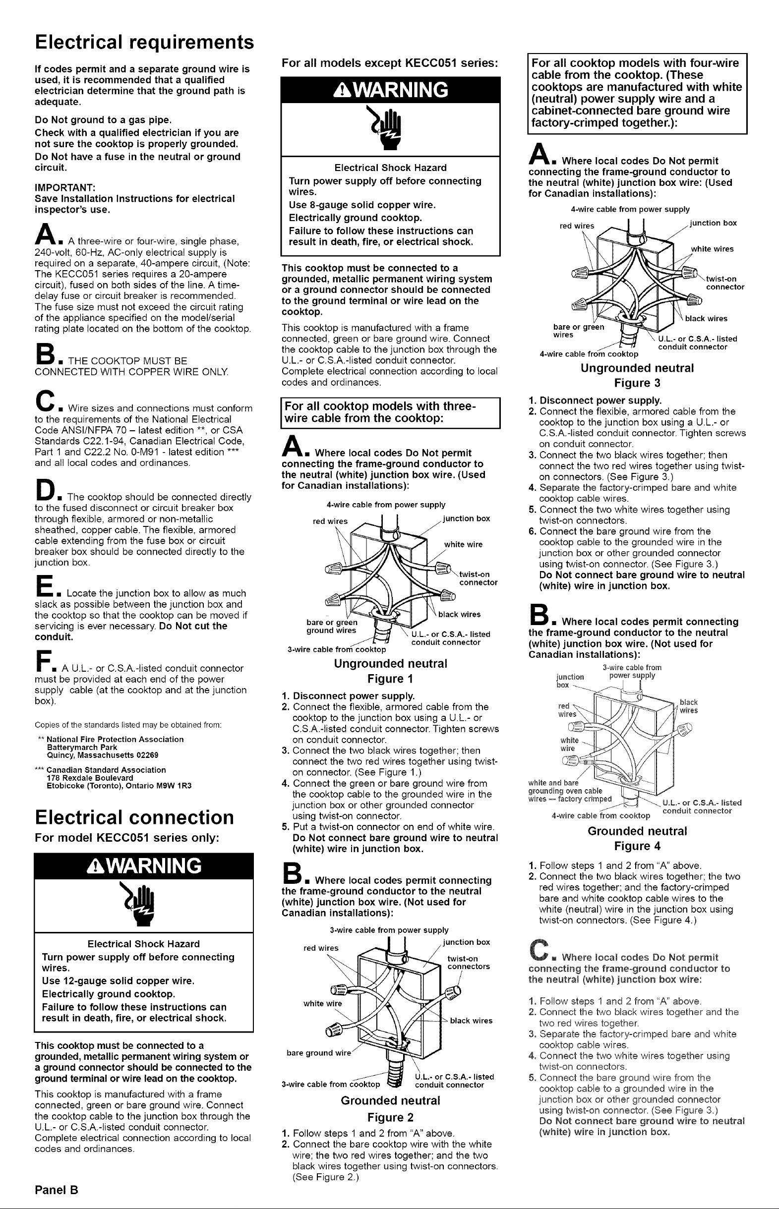
For all models except KECC051 series:
Electrical Shock Hazard
Turn power supply off before connecting
wires.
Use 8-gauge solid copper wire.
Electrically ground cooktop.
Failure to follow these instructions can
result in death, fire, or electrical shock.
This cooktop must be connected to a
grounded, metallic permanent wiring system
or a ground connector should be connected
to the ground terminal or wire lead on the
cooktop.
This cooktop is manufactured with a frame
connected, green or bare ground wire. Connect
the cooktop cable to the junction box through the
U.L.- or C.S.A.-listed conduit connector.
Complete electrical connection according to local
codes and ordinances.
For all cooktop models with three-
wire cable from the cooktop:
A= Where local codes Do Not permit
connecting the frame-ground conductor to
the neutral (white) junction box wire. (Used
for Canadian installations):
4-wire cable from power supply
red wires "unction box
white wire
connector
bare or green
ground wires
3-wire
p
black wires
U.L.- or C.S.A,- listed
conduit connector
Ungrounded neutral
Figure 1
1. Disconnect power supply.
2. Connect the flexible, armored cable from the
cooktop to the junction box using a U.L.- or
C.S.A.-listed conduit connector. Tighten screws
on conduit connector.
3. Connect the two black wires together; then
connect the two red wires together using twist-
on connector. (See Figure 1.)
4. Connect the green or bare ground wire from
the cooktop cable to the grounded wire in the
junction box or other grounded connector
using twist-on connector.
5. Put a twist-on connector on end of white wire.
Do Not connect bare ground wire to neutral
(white) wire in junction box.
B= Where local codes permit connecting
the frame-ground conductor to the neutral
(white) junction box wire. (Not used for
Canadian installations):
3-wire cable from power supply
red wire_ r__l_ ' :nw_.:it_n b°x
nectors
whitew, II -2/d
_ black wires
bare ground wire r
3-wirecablefromcooktop _ conduitconn/ _ U'L"°rC'S'Aec_iled
Grounded neutral
Figure 2
1. Follow steps 1 and 2 from "A" above.
2. Connect the bare cooktop wire with the white
wire; the two red wires together; and the two
black wires together using twist-on connectors.
(See Figure 2.)
I
For all cooktop models with four-wire
cable from the cooktop. (These
cooktops are manufactured with white
(neutral) power supply wire and a
cabinet-connected bare ground wire
factory-crimped together.):
A= Where local codes Do Not permit
connecting the frame-ground conductor to
the neutral (white) junction box wire: (Used
for Canadian installations):
4-wire cable from power supply
red wires "unction box
white wires
connector
bare or green
wires
4-wire cable from cooktop
U.L,- or C.S,A.- listed
conduit connector
Ungrounded neutral
Figure 3
1. Disconnect power supply.
2. Connect the flexible, armored cable from the
cooktop to the junction box using a U.L- or
C.S.A.-listed conduit connector. Tighten screws
on conduit connector.
3. Connect the two black wires together; then
connect the two red wires together using twist-
on connectors. (See Figure 3.)
4. Separate the factory-crimped bare and white
cooktop cable wires.
5. Connect the two white wires together using
twist-on connectors.
6. Connect the bare ground wire from the
cooktop cable to the grounded wire in the
junction box or other grounded connector
using twist-on connector. (See Figure 3.)
Do Not connect bare ground wire to neutral
(white) wire in junction box.
B= Where local codes permit connecting
the frame-ground conductor to the neutral
(white) junction box wire. (Not used for
Canadian installations):
3=wirecable from
junction power supply
box
black
wires
white and bare
grounding oven cable
wires = factory crimped U.L.- or ¢,S.A.= Hsted
4-wire cable from cooktop
conduit connector
Grounded neutral
Figure 4
1. Follow steps 1 and 2 from "A" above.
2. Connect the two black wires together; the two
red wires together; and the factory-crimped
bare and white cooktop cable wires to the
white (neutral) wire in the junction box using
twist-on connectors. (See Figure 4.)
C B Where local codes Do Not permit
connecting the frame=ground conductor to
the neutrat (white) junction box wire:
1. Follow steps 1 and 2 from "A" above.
2. Connect the two black wires together and the
two red wires together.
3. Separate the factory=crimped bare and white
cooktop cable wires.
4. Connect the two white wires together using
twist=on connectors.
5. Connect the bare ground wire from the
cooktop cable to a grounded wire in the
junction box or other grounded connector
using twist=on connector. (See Figure 3.)
Do Not connect bare ground wire to neutrat
(white) wire in junction box.
 Loading...