


KEBS277BSS00
KitchenAid KEBS277BSS00, KEBS209BSS00, KEBS179BWH00, KEBS179BBL00, KEBS279BSS00 Installation Instructions Manual
...
INSTALLATIONINSTRUCTIONS
27" (68.6 CM) AND 30"(76.2 CM) ELECTRIC
SINGLEAND DOUBLEBUILT-INOVEN
INSTRUCTIONSD'INSTALLATION
e= e=
FOURELECTRIQUEENCASTRE
27" (68,6 CM) ET30" (76,2 CM) - SIMPLEETDOUBLE
TableofContents/Table desmati@res
BUILT-IN OVEN SAFETY ............................................................... 1
INSTALLATION REQUIREMENTS ................................................ 2
Tools and Parts ............................................................................ 2
Location Requirements ................................................................ 2
Electrical Requirements ............................................................... 5
INSTALLATION INSTRUCTIONS .................................................. 6
Prepare Built-In Oven ................................................................... 6
Remove Oven Door ...................................................................... 6
Positioning Oven Feet for Multiple Cabinet Cutout Heights ....... 7
Make Electrical Connection ....................................................... 10
Install Oven ................................................................................. 12
Complete Installation ................................................................. 14
SI_CURITI_ DU FOUR ENCASTRI_ .............................................. 17
EXIGENCES D'INSTALLATION ................................................... 17
Outillage et pieces ...................................................................... 17
Exigences d'emplacement ......................................................... 18
Specifications electriques .......................................................... 20
INSTRUCTIONS D'INSTALLATION ............................................. 22
Preparation du four encastre ..................................................... 22
Depose de la porte du four ........................................................ 22
Positionnement des pieds du four pour des ouvertures
d'encastrement de hauteur differente ........................................ 23
Raccordement electrique ........................................................... 26
Installation du four ...................................................................... 28
Achever I'installation .................................................................. 30
BUILT-INOVEN SAFETY
Your safety and the safety of others are very important.
We have provided many important safety messages in this manual and on your appliance. Always read and obey all safety
messages.
This is the safety alert symbol.
This symbol alerts you to potential hazards that can kill or hurt you and others.
All safety messages will follow the safety alert symbol and either the word "DANGER" or "WARNING."
These words mean:
You can be killed or seriously injured if you don't immediately
follow instructions.
You can be killed or seriously injured if you don't follow
instructions.
All safety messages will tell you what the potential hazard is, tell you how to reduce the chance of injury, and tell you what can
happen if the instructions are not followed.
iMPORTANT:
Save for local electrical inspector's use.
iMPORTANT :
A conserver pour consultation par I'inspecteur local des installations 61ectriques.
W10351242B
INSTALLATIONREQUIREMENTS
Gather the required tools and parts before starting installation.
Read and follow the instructions provided with any tools listed
here.
Tools needed
• Phillips screwdriver
• Measuring tape
• Hand or electric drill (for wall cabinet installations)
• 1" (2.5 cm) drill bit (for wall cabinet installations)
• Level
• Flat-blade screwdriver
Parts needed
• UL listed or CSA approved conduit connector
• UL listed wire connectors
Parts supplied
• #8-14 x 1" screws - single ovens (2), double ovens (4)
• Two #8-18 x 3/8"screws - bottom vent
• Four #8-18 x 1/4"screws - bottom vent trim
• Four #8-18 x 3/8"screws - double oven feet
• Bottom vent
• Bottom vent trim
• Two feet- double oven
• Two front feet - double oven
• Four grommets - single ovens (2), double ovens (4)*
• Foam strip - single oven**
Check local codes. Check existing electrical supply. See
"Electrical Requirements."
It is recommended that all electrical connections be made by a
licensed, qualified electrical installer.
*Grommets not included with models KEBK171 B, KEBK101 B,
KEBK276B, KEBK206B, KEBS179B, KEBS109B, KEBS277B,
KEBS279B, KEBS207B, KEBS209B, KEBU109B and
KEBU209B.
**Foam strip not included with double oven.
IMPORTANT: Observe all governing codes and ordinances.
• Cabinet opening dimensions that are shown must be used.
Given dimensions provide minimum clearance with oven.
• Recessed installation area must provide complete enclosure
around the recessed portion of the oven.
• Grounded electrical supply is required. See "Electrical
Requirements" section.
• Electrical supply junction box should be located 3" (7.6 cm)
maximum below the support surface when the oven is
installed in a wall cabinet. A 1" (2.5 cm) minimum diameter
hole should have been drilled in the right rear or left rear
corner of the support surface to pass the appliance cable
through to the junction box.
NOTE: For undercounter installation, it is recommended that
the junction box be located in the adjacent right or left
cabinet. If you are installing the junction box on rear wall
behind oven, it is recommended that the junction box be
recessed and located in the upper center of the cabinet.
• Oven support surface must be solid, level and flush with
bottom of cabinet cutout.
• Floor must be able to support a single oven weight of
129 Ibs (59 kg) for 27" (68.6 cm) models or 154 Ibs (70 kg) for
30" models (76.2 cm).
• Floor must be able to support a double oven weight of
251 Ibs (114 kg) for 27" (68.6 cm) models or 288 Ibs (131 kg)
for 30" (76.2 cm) models.
IMPORTANT: To avoid damage to your cabinets, check with
your builder or cabinet supplier to make sure that the
materials used will not discolor, delaminate or sustain other
damage. This oven has been designed in accordance with
the requirements of UL and CSA International and complies
with the maximum allowable wood cabinet temperatures of
194°F (90°C).
Undercounter Installation (with cooktop installed above):
Ovens approved for this type of installation have an approval
label located on the top of the oven. Refer to undercounter
installation instructions for cutout dimensions and approved oven
cooktop combinations (separate sheet).
2
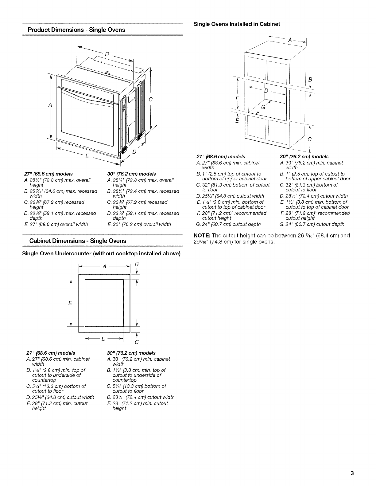
Product Dimensions - Single Ovens
A
Single Ovens Installed in Cabinet
I
B
!
C
F
i
E
J
C
27" (68.6 cm) models
A. 283/4" (72.8 cm) max. overall
height
B. 25 _" (64.6 cm) max. recessed
width
C. 26_" (67.9 cm) recessed
height
D. 23 ¼" (59.1 cm) max. recessed
depth
E. 27" (68.6 cm) overall width
30" (76.2 cm) models
A. 283/4" (72.8 cm) max. overall
height
B. 28V2" (72.4 cm) max. recessed
width
C. 26 _" (67.9 cm) recessed
height
D. 23 ¼" (59.1 cm) max. recessed
depth
E.30" (76.2 cm) overall width
Cabinet Dimensions - Single Ovens
Single Oven Undercounter (without cooktop installed above)
A B
E
27" (68.6 cm) models
A. 27" (68.6 cm) min. cabinet
width
B. 1" (2.5 cm) top of cutout to
bottom of upper cabinet door
C. 32" (81.3 cm) bottom of cutout
to floor
D. 251/2'' (64.8 cm) cutout width
E. 11/_'' (3.8 cm) min. bottom of
cutout to top of cabinet door
F. 28" (71.2 cm)* recommended
cutout height
G. 24" (60.7 cm) cutout depth
30" (76.2 cm) models
A. 30" (76.2 cm) min. cabinet
width
B. 1" (2.5 cm) top of cutout to
bottom of upper cabinet door
C. 32" (81.3 cm) bottom of
cutout to floor
D. 281/2" (72.4 cm) cutout width
E. 11/_''(3.8 cm) min. bottom of
cutout to top of cabinet door
E 28" (71.2 cm)* recommended
cutout height
G. 24" (60. 7 cm) cutout depth
NOTE: The cutout height can be between 261%e'' (68.4 cm) and
297/le'' (74.8 cm) for single ovens.
27" (68.6 cm) models
A. 27" (68.6 cm) min. cabinet
width
B. 11/_'' (3.8 cm) min. top of
cutout to underside of
cou ntertop
C. 51/4'' (13.3 cm) bottom of
cutout to floor
D. 251/2''(64.8 cm) cutout width
E. 28" (71.2 cm) min. cutout
height
30" (76.2 cm) models
A. 30" (76.2 cm) min. cabinet
width
B. 11/2'' (3.8 cm) min. top of
cutout to underside of
countertop
C. 51/4'' (13.3 cm) bottom of
cutout to floor
D. 281/_"(72.4 cm) cutout width
E. 28" (71.2 cm) min. cutout
height
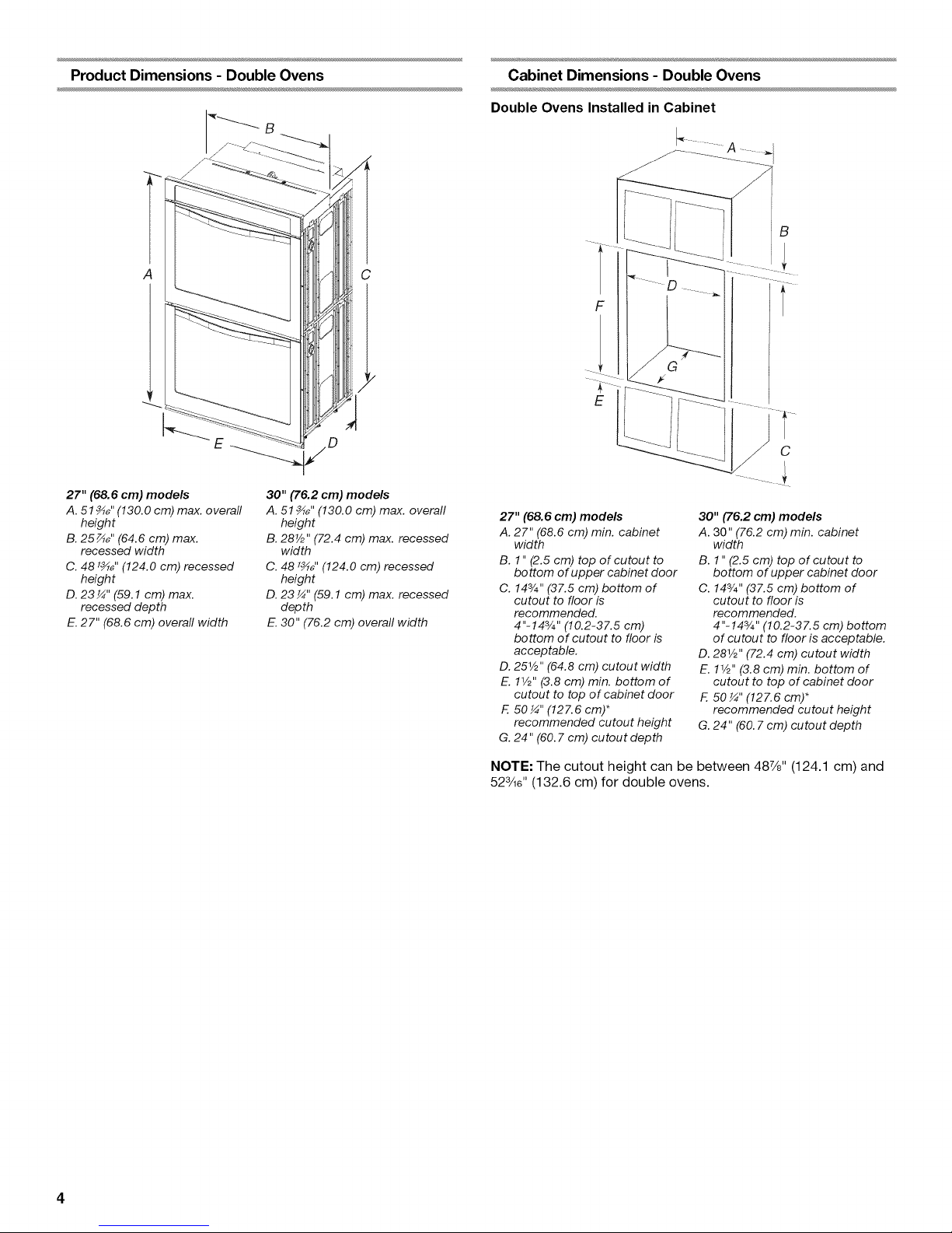
Product Dimensions - Double Ovens Cabinet Dimensions - Double Ovens
Double Ovens Installed in Cabinet
A C
F
E
B
C
I
27" (68.6 cm) models
A. 51 _" (130.0 cm) max. overall
height
B. 25_" (64.6 cm) max.
recessed width
C. 481_,, (124.0 cm) recessed
height
D. 23 ¼" (59.1 cm) max.
recessed depth
E.27" (68.6 cm) overall width
30" (76.2 cm) models
A. 51 _" (130.0 cm) max. overall
height
B. 28V2" (72.4 cm) max. recessed
width
C. 48 _" (124.0 cm) recessed
height
D. 23 ¼" (59.1 cm) max. recessed
depth
E. 30" (76.2 cm) overall width
27" (68.6 cm) models
A. 27" (68.6 cm) min. cabinet
width
B. 1" (2.5 cm) top of cutout to
bottom of upper cabinet door
C. 143/4"(37.5 cm) bottom of
cutout to floor is
recommended.
4"-143/4 ''(10.2-37.5 cm)
bottom of cutout to floor is
acceptable.
D. 251A"(64.8 cm) cutout width
E. 11/2'' (3.8 cm) min. bottom of
cutout to top of cabinet door
F. 50¼" (127.6cm)*
recommended cutout height
G. 24" (60.7 cm) cutout depth
30" ('76.2 cm) models
A. 30" (76.2 cm) min. cabinet
width
B. 1" (2.5 cm) top of cutout to
bottom of upper cabinet door
C. 143/4''(37.5 cm) bottom of
cutout to floor is
recommended.
4"-143/4 ''(10.2-37.5 cm) bottom
of cutout to floor is acceptable.
D. 281/2"(72.4 cm) cutout width
E. 1W' (3.8 cm) min. bottom of
cutout to top of cabinet door
F. 50 ¼" (127.6 cm)*
recommended cutout height
G. 24" (60.7 cm) cutout depth
NOTE: The cutout height can be between 487/8" (124.1 cm) and
523A6'' (132.6 cm) for double ovens.
Ifcodespermitandaseparategroundwireisused,itis
recommendedthataqualifiedelectricalinstallerdeterminethat
thegroundpathandthewiregaugeareinaccordancewithlocal
codes.
Checkwithaqualifiedelectricalinstallerifyouarenotsurethe
ovenisproperlygrounded.
Thisovenmustbeconnectedtoagroundedmetal,permanent
wiringsystem.
Besurethattheelectricalconnectionandwiresizeareadequate
andinconformancewiththeNationalElectricalCode,ANSI/
NFPA70-latesteditionorCSAStandardsC22.1-94,Canadian
ElectricalCode,Part1andC22.2No.O-M91-1atestedition,and
alllocalcodesandordinances.
Acopyoftheabovecodestandardscanbeobtainedfrom:
NationalFireProtectionAssociation
1BatterymarchPark
Quincy,MA02169-7471
CSAInternational
8501EastPleasantValleyRoad
Cleveland,OH44131-5575
Electrical Connection
To properly install your oven, you must determine the type of
electrical connection you will be using and follow the instructions
provided for it here.
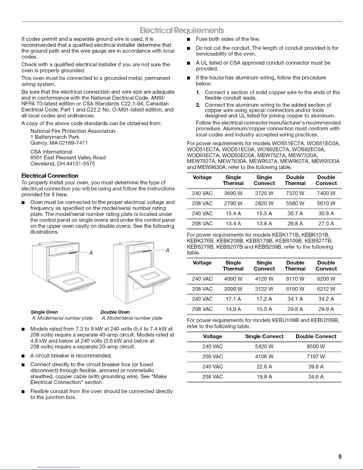
• Oven must be connected to the proper electrical voltage and
frequency as specified on the model/serial number rating
plate. The model/serial number rating plate is located under
the control panel on single ovens and under the control panel
on the upper oven cavity on double ovens. See the following
illustrations.
Fuse both sides of the line.
• Do not cut the conduit. The length of conduit provided is for
serviceability of the oven.
• A UL listed or CSA approved conduit connector must be
provided.
• If the house has aluminum wiring, follow the procedure
below:
1. Connect a section of solid copper wire to the ends of the
flexible conduit leads.
2. Connect the aluminum wiring to the added section of
copper wire using special connectors and/or tools
designed and UL listed for joining copper to aluminum.
Follow the electrical connector manufacturer's recommended
procedure. Aluminum/copper connection must conform with
local codes and industry accepted wiring practices.
For power requirements for models WOS51 EC7A, WOS51 ECOA,
WOD51 EC7A, WOD51 ECOA, WOS92EC7A, WOS92ECOA,
WOD93EC7A, WOD93ECOA, MEW7527A, MEW7530A,
MEW7627A, MEW7630A, MEW9537A, MEW9627A, MEW9530A
and MEW9630A, refer to the following table.
Voltage Single Single Double Double
Thermal Convect Thermal Convect
240 VAC 3690 W 3720 W 7370 W 7400 W
208 VAC 2790 W 2820 W 5580 W 5610 W
240 VAC 15.4 A 15.5 A 30.7 A 30.8 A
208 VAC 13.4 A 13.6 A 26.8 A 27.0 A
For power requirements for models KEBK171 B, KEBK101 B,
KEBK276B, KEBK206B, KEBS179B, KEBS109B, KEBS277B,
KEBS279B, KEBS207B and KEBS209B, refer to the following
table.
Single Oven Double Oven
A. Model/serial number plate A. Model/serial number plate
Models rated from 7.3 to 9 kW at 240 volts (5.4 to 7.4 kW at
208 volts) require a separate 40-amp circuit. Models rated at
4.8 kW and below at 240 volts (3.6 kW and below at
208 volts) require a separate 20-amp circuit.
A circuit breaker is recommended.
Connect directly to the circuit breaker box (or fused
disconnect) through flexible, armored or nonmetallic
sheathed, copper cable (with grounding wire). See "Make
Electrical Connection" section.
Flexible conduit from the oven should be connected directly
to the junction box.
Voltage Single Single Double Double
Thermal Convect Thermal Convect
240 VAC 4090 W 4120 W 8170 W 8200 W
208 VAC 3099 W 3122 W 6190 W 6212 W
240 VAC 17.1 A 17.2 A 34.1 A 34.2 A
208 VAC 14.9 A 15.0 A 29.8 A 29.9 A
For power requirements for models KEBU109B and KEBU209B,
refer to the following table.
Voltage Single Convect Double Convect
240 VAC 5420 W 9500 W
208 VAC 4106 W 7197 W
240 VAC 22.6 A 39.6 A
208 VAC 19.8 A 34.6 A
INSTALLATIONINSTRUCTIONS
, ,_ _H_,___:_
1. Decide on the final location for the oven. Avoid drilling or
cutting into house wiring during installation.
Excessive Weight Hazard
Use two or more people to move and install oven.
Failure to do so can result in back or other injury.
2. To avoid floor damage, set the oven onto cardboard prior to
installation. Do not use handle or any portion of the front
frame for lifting.
3. Remove the shipping materials and tape from the oven.
4. Remove the hardware package from inside the bag
containing literature.
5. Remove and set aside racks and other parts from inside the
oven.
6. If installing a single oven below a cooktop, remove the
adhesive backing from the foam strip and press it to the back
of the control panel.
NOTE: When the cooktop is installed inthe cabinet, the top
edge of the foam strip should be approximately 3/8"(10 mm)
from the top edge of the control panel. Make sure the foam
strip is positioned against the cabinet face.
n ©
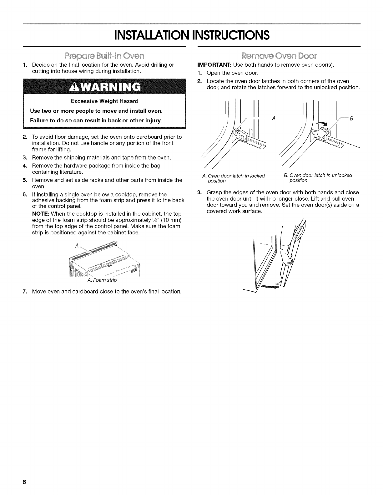
IMPORTANT: Use both hands to remove oven door(s).
1. Open the oven door.
2. Locate the oven door latches in both corners of the oven
door, and rotate the latches forward to the unlocked position.
A. Oven door latch in locked
position
3.
Grasp the edges of the oven door with both hands and close
the oven door until it will no longer close. Lift and pull oven
door toward you and remove. Set the oven door(s) aside on a
covered work surface.
B. Oven door latch in unlocked
position
A. Foamstrip
7. Move oven and cardboard close to the oven's final location.
6
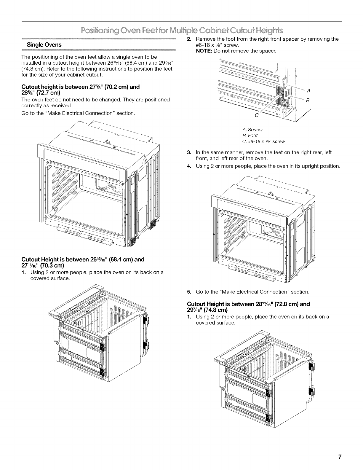
2. Remove the foot from the right front spacer by removing the
Single Ovens #8-18 x 3/8"screw.
NOTE: Do not remove the spacer.
The positioning of the oven feet allow a single oven to be
installed in a cutout height between 2@sAe'' (68.4 cm) and 297Ae''
(74.8 cm). Refer to the following instructions to position the feet
for the size of your cabinet cutout.
CL£ou i
Cutout height is between 27%" (70.2 cm) and
28%" (72.7 cm)
The oven feet do not need to be changed. They are positioned
correctly as received.
Go to the "Make Electrical Connection" section.
A
B
C
A. Spacer
B. Foot
C. #8-18 x _" screw
3. In the same manner, remove the feet on the right rear, left
front, and left rear of the oven.
4. Using 2 or more people, place the oven in its upright position.
Cutout Height is between 26_A6'' (68.4 cm) and
27_A6"(70.3 cm)
1. Using 2 or more people, place the oven on its back on a
covered surface.
5. Go to the "Make Electrical Connection" section.
Cutout Height is between 28_A6" (72.8 cm) and
297A6'' (74.8 cm)
1. Using 2 or more people, place the oven on its back on a
covered surface.
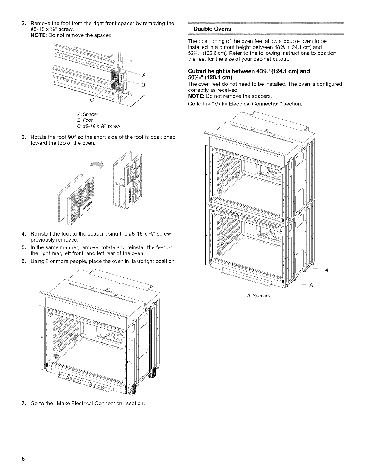
2.
Remove the foot from the right front spacer by removing the
#8-18 x 3/8"screw.
NOTE: Do not remove the spacer.
Double Ovens
The positioning of the oven feet allow a double oven to be
installed in a cutout height between 48%" (124.1 cm) and
52¾e" (132.6 cm). Refer to the following instructions to position
the feet for the size of your cabinet cutout.
A
B
C
A. Spacer
B. Foot
C. #8-18 x _" screw
3.
Rotate the foot 90 ° so the short side of the foot is positioned
toward the top of the oven.
4. Reinstall the foot to the spacer using the #8-18 x 3/8"screw
previously removed.
5. In the same manner, remove, rotate and reinstall the feet on
the right rear, left front, and left rear of the oven.
6. Using 2 or more people, place the oven in its upright position.
Cutout height is between 48%" (124.1 cm) and
507A6'' (128.1 cm)
The oven feet do not need to be installed. The oven is configured
correctly as received.
NOTE: Do not remove the spacers.
Go to the "Make Electrical Connection" section.
A
7. Go to the "Make Electrical Connection" section.
A
A. Spacers
8
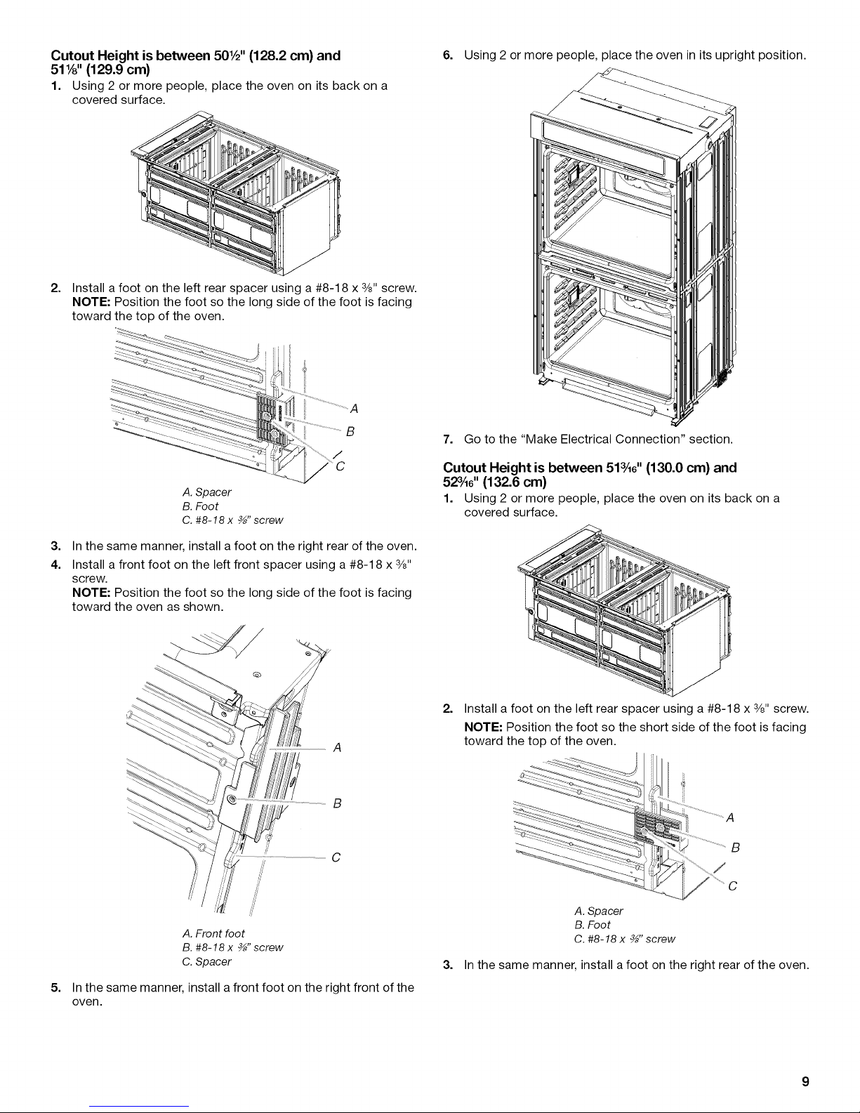
CutoutHeightisbetween501/2''(128.2cm)and
511/8"(129.9cm)
1. Using 2 or more people, place the oven on itsback on a
covered surface.
2.
Install a foot on the left rear spacer using a #8-18 x 3/8"screw.
NOTE: Position the foot so the long side of the foot is facing
toward the top of the oven.
6. Using 2 or more people, place the oven in its upright position.
7. Go to the "Make Electrical Connection" section.
A. Spacer
B. Foot
C. #8-18 x _" screw
3.
In the same manner, install a foot on the right rear of the oven.
4.
Install a front foot on the left front spacer using a #8-18 x 3/8"
screw.
NOTE: Position the foot so the long side of the foot is facing
toward the oven as shown.
A
B
Cutout Height is between 513A6'' (130.0 cm) and
523A6'' (132.6 cm)
1. Using 2 or more people, place the oven on its back on a
covered surface.
2.
Install a foot on the left rear spacer using a #8-18 x 3/8"screw.
NOTE: Position the foot so the short side of the foot is facing
toward the top of the oven.
B
#
A. Front foot
B. #8-18x _" screw
C. Spacer
5.
In the same manner, install a front foot on the right front of the
oven.
C
A. Spacer
B. Foot
C. #8-18 x _" screw
3. In the same manner, install a foot on the right rear of the oven.
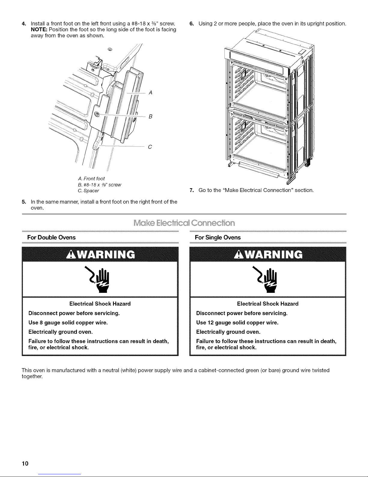
4. 6. Using2ormorepeople,placetheoveninitsuprightposition.Installafrontfootontheleftfrontusinga#8-18x3/8"screw.
NOTE:Positionthefootsothelongsideofthefootisfacing
awayfromtheovenasshown.
B
//
A. Front foot
B. #8-18x _" screw
C. Spacer
5=
In the same manner, install a front foot on the right front of the
oven.
7. Go to the "Make Electrical Connection" section.
Mcs E cc' Conn®c on
For Double Ovens
Electrical Shock Hazard
Disconnect power before servicing.
Use 8 gauge solid copper wire.
Electrically ground oven.
Failure to follow these instructions can result in death,
fire, or electrical shock.
This oven is manufactured with a neutral (white) power supply wire and a cabinet-connected green (or bare) ground wire twisted
together.
For Single Ovens
Electrical Shock Hazard
Disconnect power before servicing.
Use 12 gauge solid copper wire.
Electrically ground oven.
Failure to follow these instructions can result in death,
fire, or electrical shock.
10
 Loading...