

Page 1
ELECTRIC BUILT-IN
SINGLE & DOUBLE OVENS
MODELS (singles):
KEt31140/141/170/171
KEBS145/146/176/177
SCO-1243/2433/1273/2733
MODELS (doubles):
KEB1240/241/270/271
KEBS245/246/276/277
SCO-2243124431227312743
INSTALLATION
INSTRUCTIONS
INSTALLER: FINAL CHECK LIST
IMPORTANT:
LEAVE THESE INSTRUCTIONS FOR USE BY LOCAL ELECTRICAL INSPECTOR
PLACEMENT OF UNIT
@ 1. Properly positioned-level, aligned and square with cabinet opening.
u 2. Anchored securely to cabinet.
n 3. Installation debns removed.
ELECTRICAL
n 1. Oven properly grounded.
0 2. Separate 1201240 volt or 12Oi208 volt, 60 Hr. single phase branch circuit of proper ampacity,
and protected by a time-delay fuse or circuit breaker of proper size.
c 3. All connections made in accordance with National Electrical Code, ANSliNFPA 70.latest
edition and local codes and ordinances.
OPERATIONAL
3 1.0
il 2. Knobs securely in place and rotate freely wlthout rubbing edges of control panel glass
J 3. All lights function properly.
-~ 1
L
r-7
.-J 5. Doors properly adjusted, open and close smoothly
ven racks installed and slide freely In all posrtlons.
holes.
J 4. Clock timer buzzer operates.
_
’ 6. Selector switch functions in all modes
,
7 Unless Instructed to leave for owner. remove all tags, iabels and Internal packing
materials.
8 Oven has been wiped clean to remove flnqermarks and other smudges
THANK YOU INSTALLER:
1 Complete lr~stallatlo:l Check
2. Leave all literature for customer
3 Notify dealer that ihstallatlon
LISA
IS
completed.
FDR DETAILED INSTRUCTIONS, FOLLOW METHODS DESCRIBED IN THIS FOLDER.
Page 2
IMPORTANT: Read Before Installing to Save Time, Work,
assure proper performance, and owner’s warranty protection.
INSTALLATION INSTRUCTIONS
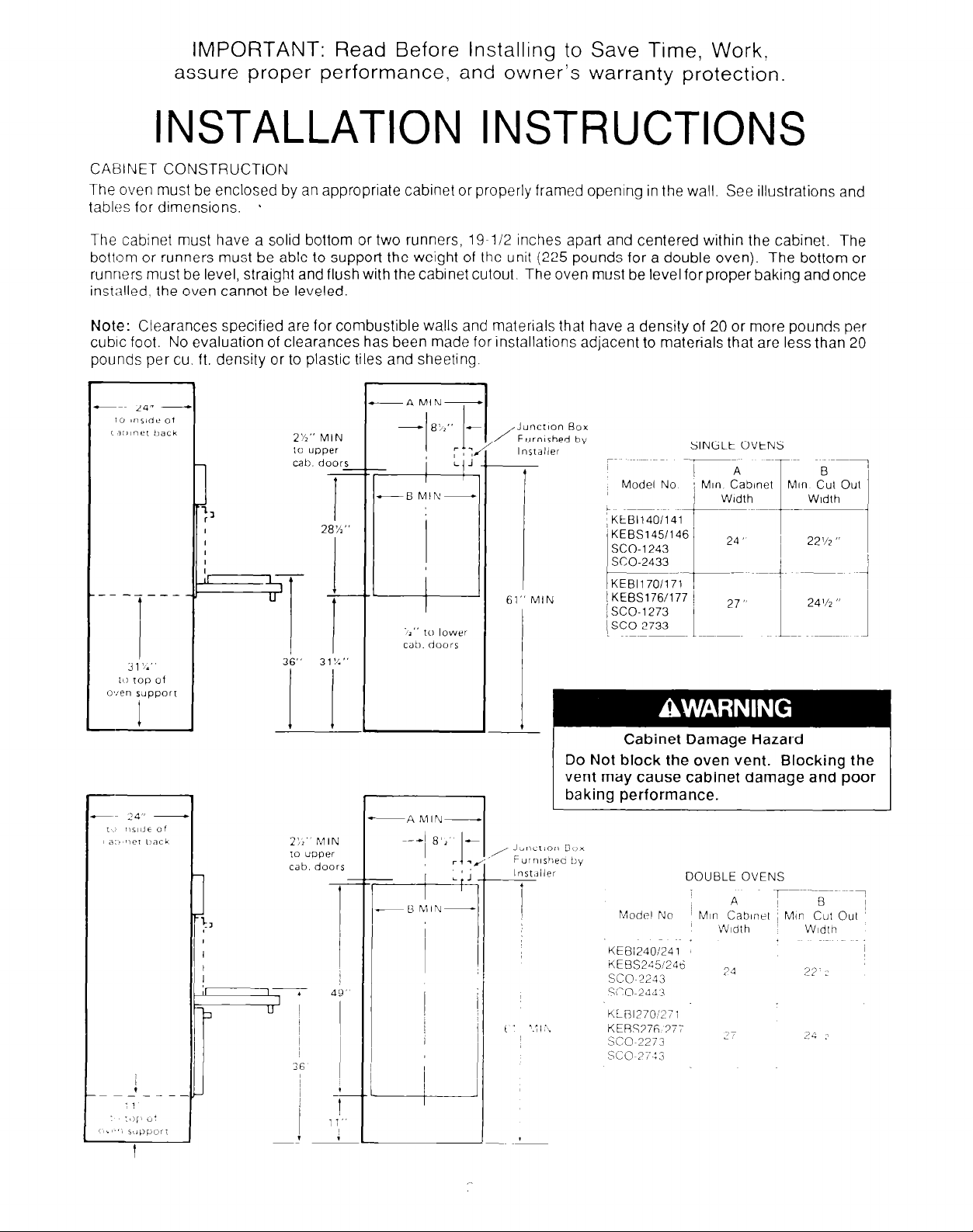
CABINET CONSTRUCTION
The oven must be enclosed by an appropriate cabinet or properly framed opening in the wall. See illustrations and
tables for dimensions. b
The cabinet must have a solid bottom or two runners, 19-112 inches apart and centered within the cabinet. The
bottom or runners must be able to support the weight of the unit (225 pounds for a double oven). The bottom or
runners must be level, straight and flush with the cabinet cutout. The oven must be level forproper baking and once
installed. the oven cannot be leveled.
Note: Clearances specified are for combustible walls and materials that have a density of 20 or more pounds per
cubic foot. No evaluation of clearances has been made for installations adjacent to materials that are less than 20
pounds per cu. ft. density or to plastic tiles and sheeting.
-- ---_-
2%” MIN
1” upper
28%”
L
Junction Box
/
Furnished by
lns1aller
61” MIN
SINGLE OVENS
Model No
Cabinet Damage Hazard
Do Not
block the oven vent. Blocking the
vent may cause cabinet damage and poor
baking performance.
-A hIIN-
KEBS245!246
SC0 2243
23
22.2
Page 3

ELECTRICAL REQUIREMENTS
Electrical Shock Hazard
- Electrical ground is required on this appliance.
l
Improper connection of the equipment-grounding conductor line can result in
electrical shock.
. Check with a qualified electrician if you are in doubt as to whether the appliance is
properly grounded. Do Not modify the power supply cord plug. If it will not fit the
outlet, have a proper outlet installed by a qualified electrician.
- Do Not use an extension cord with this appliance. Such use may result in a fire,
electrical shock or other personal injury.
. Do Not have a fuse in the neutral or ground circuit. A fuse in the neutral or ground
circuit could result in an electrical shock.
l
This appliance must be connected to a grounded, metallic permanent wiring system;
or a grounding conductor should be connected to the grounding terminal or lead on
the appliance. Failure to do so could result in an electrical shock.
I
It is the customer’s responsibility tocontact a qualified electrical installer to assure that electrical installation is
adequate and in conformance with National Electrical Code, ANSliNFPA 70.latest edition and local codes and
ordinances.
A 1201240.volt or 1201208 volt, 60 Hz, AC only, fused electrical supply is required. A time-delay fuse or circuit breaker
is recommended. It is recommended that a separate circuit serving only this appliance be provided. It is the personal
responsibility of the customer to have a properly grounded, 3-prong wall receptacle installed by a qualified
electrician.
I
The following amperage circuits must be provided.
When installed in a mobile home, the installation must conform to the Manufactured Home Construction and Safety
Standards, Title 24 CFR, Part 3280 (formerly the Federal Standard for Mobile Home Construction and Safety, Title
24. HUD, Part 280)
TABLE 1
KEBS177
Model No
[ -%axlmum Wattage (KW)
240/208 Volt
3.713 0
Fuse or Breaker
Size Required
KEBI140/141/170/171
KEBS145/146/176
SCO-1243/1273
813 0
I
3
I
30 Amps
SCO-243312733
KEBl240/270
SCO-224312273
KEBS277
KEBl241/271
KEBS24512461276
X0-2443/2743
I
c
6 O/5 0
7 315 8
7 516 0
40 Amps
/
_~--~~.~~
Page 4

UNPACKING THE UNIT
Personal Injury
More than one person is required to lift or move
the oven because of its weight and size.
Keep shipping base under oven. Failure to do so
could cause damage to floor covering.
Failure to follow these instructions may result in
personal injury.
L
The oven should be left on the carton base untrl it IS ready to put
Into the cabinet It is also recommended that the pads over the door(s)
be left in place. These precautions will reduce the possrbrllty of
damage to the front of the unit and the bottom of the front frame.
Remove all cords, tape and wire used to hold various parts
tion during shipment. Remove oven racks from the inside of the oven
and put to one side while oven IS being installed In cabinet Take
broiler pan and grid from packing on top of the oven and keep with
literature packet in a localion where they will be retalned by the
owner.
ELECTRICAL CONNECTION
in
POSI-
Floor Damage
To Remove Oven Racks
Slide rack forward unl~l bar on back of rack
touches first slop
Lilt front of rack unl~l rear porllon of rack slides
oul between front Iwo slops
Electrical Shock Hazard
Disconnect power supply before making any electrical connections.
Failure to do so may result in electrical shock.
Connect the conduit from the oven to the junctron box and properly connect to the power supply leads. (Bare to
ground, black to L2, red to Ll, white to neutral or according to local code.)
GROUNDING -THE OVEN MUST BE GROUNDED
Do not work on the oven wiring until the oven has beer; positively grounded
The oven frame is grounded through the bare grounding Lvlre
wire at the junction box
Connect the whrte neutral to the service neutral
INSTALLING THE UNIT IN CABINET
Potential Personal Injury
- Use both hands to remove oven doors.
- Grasp only the sides of the oven door.
lifting.
Failure to properly grasp oven door could result in damage to product or personal injury.
Do
Not
use
any portion of the front frame
or trim for
The doors should be remoded
wrile lifting It into the cabinet.
to decrease the weight of the oven and provide a better hand-hold on the oven
Page 5

A
To Remove Doors (See Fig. 1)
Use caution! Oven door IS heavy
1 Open door completely.
2. Depress finger tab In oven door hinge area. Push tab toward oven.
Loft tab away from door liner and slide toward top of oven door.
3 Repeat step ? for other side of door.
4.
Close door until approximately 5 inches from fully closed posltion.
5. Slide door off the hinge
6 Repeat steps 1 through 5 for other door on double ovens.
BE SURE THAT PHENOLIC SPACERS AT EACH SIDE OF OVEN
ARE IN PLACE TO PROVIDE PROPER AIR FLOW
BETWEEN CABINET AND OVEN.
arm assemblies.
B When oven has been placed
into cabinet; install exterior trim, if used,
or the bottom trim strip. Where the exterior trim is to be installed on the
oven, omit step C and proceed with the instructions supplied with the trim.
C The bottom trim strip is placed on lower edge of front frame. This is done
by loosening the three screws at the bottom of the front frame. Slide the
trim strip under the screw heads until the strip meets the lower corners
of the front frame (See Fig. 2). Tighten screws to hold to front frame.
Personal Injury Hazard
Securely fasten wall oven to cabinets using the screws provided
(4 screws for a double oven or 2 screws for a single oven).
Failure to do so could cause oven to move or tip during use and
result in personal injury.
D Secure oven to cabinet with a8 screws provided. Do not overtighten
screws. Edge of front frame should be parallel to cabinet or front edge
of exterior trim. Disregard any excess screws that are left after all screw
holes in front frame have been used.
E Install unwrapped oven racks in oven.
F Reinstall the doors (See Fig. 1).
1
Slide door hinge arms until firmly seated.
2 Lower door to full open position.
3 Push finger tabs to back. Depress the tabs and slide forward.
4 Close and reopen door slowly to make sure it has been replaced
properly.
5 Repeat steps 1 through 4 for other door on double oven.
Page 6

DOOR ADJUSTMENT CHECK
NEWSPAPER STRIPS
A-
TOP OF DOOR
NEWSPAPER STRIPSJ
BOTTOM OF DOOR
NEWSPAPER STRIPS
SIDE OF DOOR
PROPER DOOR
ADJUST UP OR DOWN2
TO ALIGN DOOR
Speclficatlons Subject to C?ange WIthout Notlce
Place 2 ” x 18 ” slrlps of newspaper In locatlons Indicated by lllustratlon Allow one end
of the paper to extend 1130 the oven cavity.
Pull gently at each piece of paper. If door IS
properly adjusted, each piece of paper WIII
offer firm resistance when pulled. When door
IS out of adjustment, slide unit out far enough
lo expose hinges on each side Loosen
screws and move bottom of door to a proper
fit. After completing adjustment tlghlen all
screws In hinges
Part No 3177123 Rev B
@I969 tiltchenAid. Inc.
Prepared
by KItchenAId. St. Joseph, Mchigan 49085
Printed in U.S.A
 Loading...