

KitchenAid KEBC167VSS Quick Start Manual

INSTALLATION INSTRUCTIONS
36" (91.4 CM) ELECTRIC SINGLE BUILT-IN OVEN
INSTRUCTIONS D’INSTALLATION
FOUR ÉLECTRIQUE ENCASTRÉ DE 36" (91,4 CM) - SIMPLE
Table of Contents/Table des matières
BUILT-IN OVEN SAFETY ................................ 2
INSTALLATION REQUIREMENTS ................. 3
Tools and Parts ............................................. 3
Location Requirements................................. 3
Electrical Requirements ................................ 4
INSTALLATION INSTRUCTIONS ................... 5
Prepare Built-In Oven.................................... 5
Remove Oven Trim ....................................... 5
Make Electrical Connection .......................... 6
Install Oven.................................................... 7
Complete Installation .................................... 8
SÉCURITÉ DU FOUR ENCASTRÉ ..................9
EXIGENCES D'INSTALLATION.....................10
Outillage et pièces ....................................... 10
Exigences d'emplacement ..........................10
Spécifications électriques............................11
INSTRUCTIONS D’INSTALLATION ..............12
Préparation du four encastré.......................12
Dépose des garnitures du four....................12
Raccordement électrique ............................13
Installation du four ....................................... 14
Achever l'installation....................................15
IMPORTANT: Save for local electrical inspector's use.
IMPORTANT : À conserver pour consultation par l'inspecteur local des installations électriques.
8304426
BUILT-IN OVEN SAFETY
Your safety and the safety of others are very important.
We have provided many important safety messages in this manual and on your appliance. Always read and obey all safety
messages.
This is the safety alert symbol.
This symbol alerts you to potential hazards that can kill or hurt you and others.
All safety messages will follow the safety alert symbol and either the word “DANGER” or “WARNING.”
These words mean:
You can be killed or seriously injured if you don't immediately
DANGER
WARNING
All safety messages will tell you what the potential hazard is, tell you how to reduce the chance of injury, and tell you what can
happen if the instructions are not followed.
follow instructions.
can be killed or seriously injured if you don't
You
instructions.
follow
2
INSTALLATION REQUIREMENTS
Tools and Parts
Gather the required tools and parts before starting installation.
Read and follow the instructions provided with any tools listed
here.
To o ls ne e d e d
■ Phillips screwdriver
■ Measuring tape
■ Hand or electric drill (for wall cabinet installations)
■ 1" (25 mm) drill bit (for wall cabinet installations)
■ Level
Parts needed
■ UL listed or CSA approved conduit connector
■ UL listed wire connectors
Parts supplied
■ # 8–14 x 1" screws - single oven (2), double oven (4)
■ Bottom vent (supplied on some models)
■ Two # 8–18 x ³⁄₈" screws - bottom vent (supplied on some
models)
Check local codes. Check existing electrical supply. See
“Electrical Requirements.”
It is recommended that all electrical connections be made by a
licensed, qualified electrical installer.
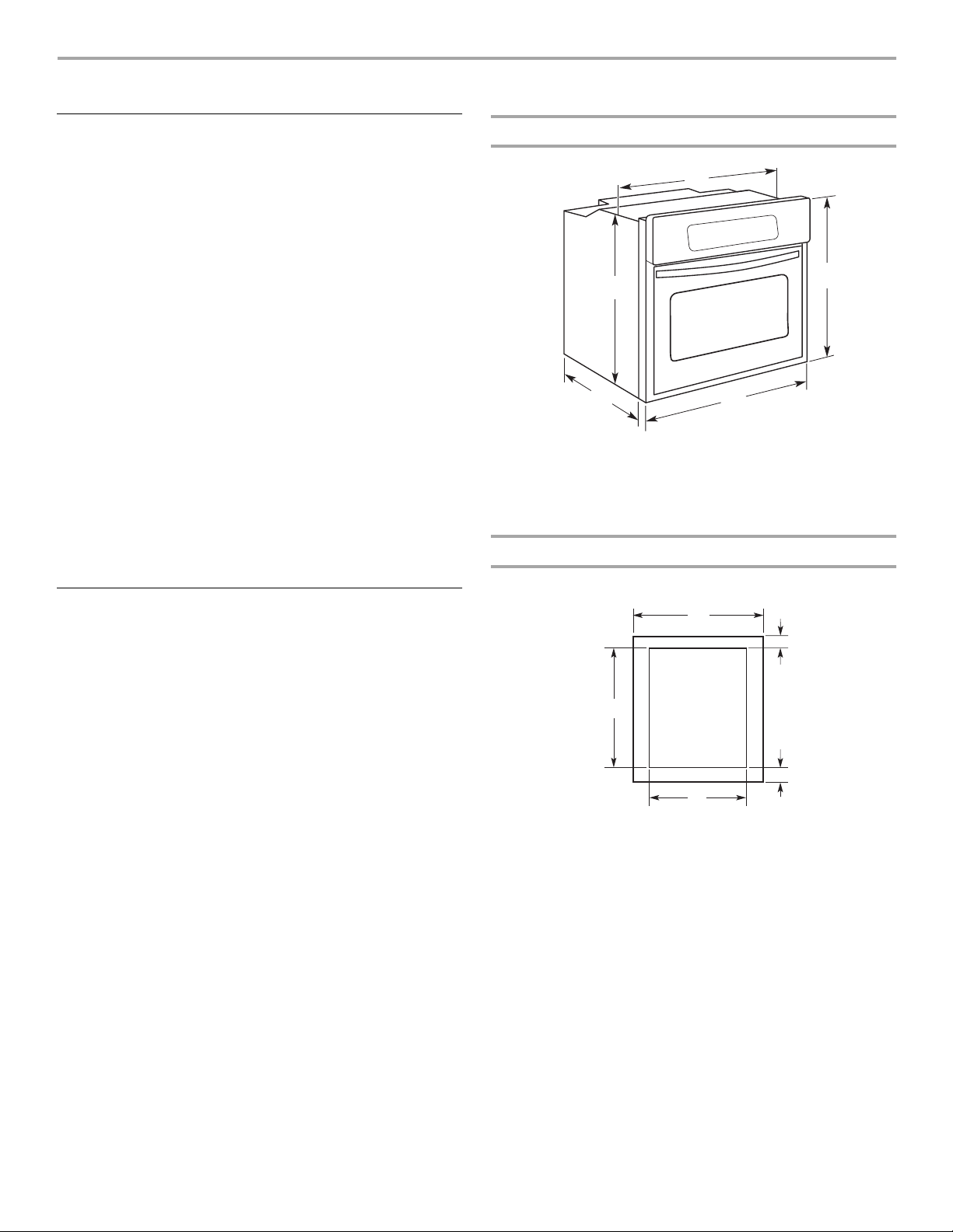
Product Dimensions
A
E
D
A. 34³⁄₈" (87.3 cm) max. recessed width
B. 29" (73.7 cm) max. overall height
C. 35³⁄₄" (90.8 cm) overall width
D. 23" (58.4 cm) max. recessed depth
E. 27¹⁄₂" (69.9 cm) recessed height
C
B
Cabinet Dimensions
Single Oven Undercounter (without cooktop installed above)
Location Requirements
Make sure you have everything needed for correct installation. It is
the responsibility of the installer to comply with the installation
clearances specified in these instructions.
IMPORTANT: Observe all governing codes and ordinances.
■ Cabinet opening dimensions that are shown must be used.
Given dimensions provide minimum clearance with oven.
■ Recessed installation area must provide complete enclosure
around the recessed portion of the oven.
■ Grounded electrical supply is required. See “Electrical
Requirements” section.
■ Electrical supply junction box should be located 3" (7.6 cm)
maximum below the support surface when the oven is
installed in a wall cabinet. A 1" (2.5 cm) minimum diameter
hole should have been drilled in the right rear or left rear
corner of the support surface to pass the appliance cable
through to the junction box.
NOTE: For undercounter installation, it is recommended that
the junction box be located in the adjacent right or left
cabinet. If you are installing the junction box on rear wall
behind oven, the junction box must be recessed and located
in the upper or lower right or left corner of the cabinet;
otherwise, the oven will not fit into the cabinet opening.
■ Oven support surface must be solid, level and flush with
bottom of cabinet cutout. Floor must be able to support a
weight of 172 lbs (78 kg).
Undercounter Installation (with cooktop installed above):
Ovens approved for this type of installation have an approval label
located on the top of the oven. Refer to undercounter installation
instructions for cutout dimensions and approved oven cooktop
combinations (separate sheet).
A
B
E
D
A. 36" (91.4 cm) min. cabinet width
B. 1¹⁄₂" (3.8 cm) min. top of cutout to
underside of countertop
C. 5¹⁄₄" (13.3 cm) bottom of cutout to floor
D. 34¹⁄₂" (87.6 cm) cutout width
E. 27³⁄₄" (70.5 cm) min. cutout height
C
3
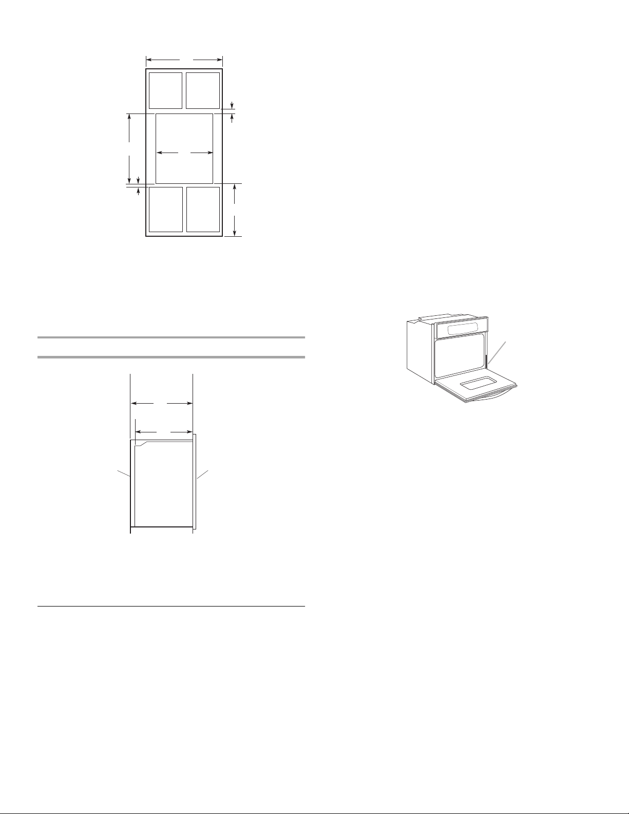
Single Oven Installed in Cabinet
F
E
A. 36" (91.4 cm) min. cabinet width
B. 1" (2.5 cm) top of cutout to bottom of upper
cabinet door
C. 32" (81.3 cm) bottom of cutout to floor
D. 34¹⁄₂" (87.6 cm) cutout width
E. 1¹⁄₂" (3.8 cm) min. bottom of cutout to top of
cabinet door
F. 2 7 ³⁄₄" (70.5 cm) min. cutout height
Cabinet Side View
It is not recommended to have a fuse in the neutral or ground
circuit.
A
This oven must be connected to a grounded metal, permanent
wiring system.
Be sure that the electrical connection and wire size are adequate
B
and in conformance with the National Electrical Code, ANSI/NFPA
70-latest edition or CSA Standards C22.1-94, Canadian Electrical
Code, Part 1 and C22.2 No. O-M91-latest edition, and all local
codes and ordinances.
A copy of the above code standards can be obtained from:
D
National Fire Protection Association
One Batterymarch Park
Quincy, MA 02269
CSA International
8501 East Pleasant Valley Road
Cleveland, OH 44131-5575
C
Electrical Connection
To properly install your oven, you must determine the type of
electrical connection you will be using and follow the instructions
provided for it here.
■ Oven must be connected to the proper electrical voltage and
frequency as specified on the model/serial number rating
plate. The model/serial number rating plate is located at the
bottom of the right-hand mounting rail. See the following
illustration.
A
A
B
E
A. 23¹⁄₄" (59.1 cm) min. cutout depth
B. 23" (58.4 cm) recessed oven depth
C. Oven front
D. Recessed oven
E. Cabinet
D
C
Electrical Requirements
If codes permit and a separate ground wire is used, it is
recommended that a qualified electrical installer determine that
the ground path and wire gauge are in accordance with local
codes.
It is not recommended to ground to a gas pipe.
Check with a qualified electrical installer if you are not sure the
oven is properly grounded.
Single Oven
A. Model/serial number plate
■ Models rated at 7.2 kW and below at 240 volts (5.4 kW and
below at 208 volts) require a separate 30-amp circuit.
■ A time-delay fuse or circuit breaker is recommended.
■ Connect directly to the fused disconnect (or circuit breaker
box) through flexible, armored or nonmetallic sheathed,
copper cable (with grounding wire). See “Make Electrical
Connection” section.
■ Flexible cable from appliance should be connected directly to
the junction box.
■ Fuse both sides of the line.
■ Do not cut the conduit. The length of conduit provided is for
serviceability of the oven.
■ A UL listed or CSA approved conduit connector must be
provided.
■ If the house has aluminum wiring, follow the procedure below:
1. Connect a section of solid copper wire to the pigtail
leads.
2. Connect the aluminum wiring to the added section of
copper wire using special connectors and/or tools
designed and UL listed for joining copper to aluminum.
Follow the electrical connector manufacturer's recommended
procedure. Aluminum/copper connection must conform with
local codes and industry accepted wiring practices.
4
INSTALLATION INSTRUCTIONS
A
A
Prepare Built-In Oven
1. Decide on the final location for the oven. Locate existing
wiring to avoid drilling into or severing wiring during
installation.
WARNING
Excessive Weight Hazard
Use two or more people to move and install oven.
Failure to do so can result in back or other injury.
2. To avoid floor damage, set the oven onto cardboard prior to
installation. Do not use handle or any portion of the front
frame for lifting.
On models with shipping feet attached:
To avoid product damage, do not remove the shipping feet at
the front lower corners of the oven. The shipping feet will
protect the lower oven trim until the oven is inserted into
cabinet.
3. Remove the shipping materials and tape from the oven.
4. Remove the hardware package from inside the bag containing
literature.
5. Remove and set aside racks and other parts from inside the
oven.
6. Move oven and cardboard close to the oven’s final location.
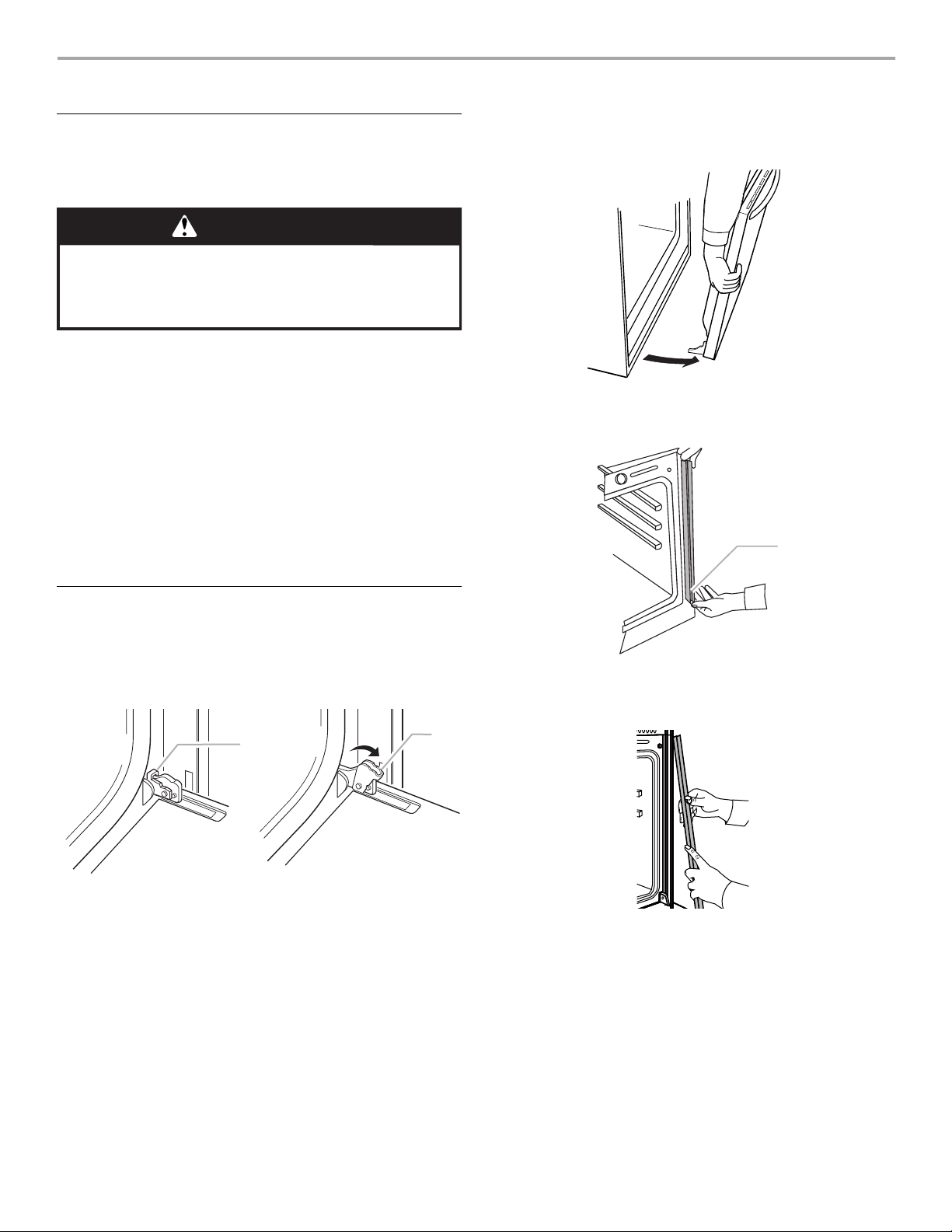
3. Grasp the edges of the oven door with both hands and close
the oven door until it will no longer close. Lift and pull oven
door toward you and remove. Set the oven door aside on a
covered work surface.
4. Remove bottom screw on each side of the oven trim
5. Grasp the bottom end of trim and pull away from oven.
Remove Oven Trim
IMPORTANT: Use both hands to remove oven doors.
1. Open the oven door.
2. Locate the oven door latches in both corners of the oven door,
and rotate the latches forward to the unlocked position.
B
A. Oven door latch in locked
position
B. Oven door latch in unlocked
position
A. Remove trim screw and pull out.
6. Slide top end of trim downward to remove trim from oven. Set
trim aside.
5
 Loading...