

Page 1

INSTALLATION INSTRUCTIONS
CommerCial-Style Dual Fuel ConveCtion rangeS
30"(76.2Cm),36"(91.4Cm)anD48" (121.9 Cm)
For residential use only
INSTRUCTIONS D’INSTALLATION
CuiSinièreS à ConveCtion à Double CombuStible
DetypeCommerCial
30"(76,2Cm),36"(91,4 Cm) et 48" (121,9 Cm)
Pour utilisation résidentielle uniquement
Table of Contents/Table des matières
RANGE SAFETY .............................................................................2
INSTALLATION REQUIREMENTS .................................................4
Tools and Parts .............................................................................4
Location Requirements ................................................................6
Water Filtration System Location Requirements .........................8
Water Supply Requirements ........................................................8
Electrical Requirements – U.S.A. Only .........................................9
Electrical Requirements – Canada Only ....................................10
Gas Supply Requirements .........................................................10
INSTALLATION INSTRUCTIONS .................................................12
Unpack the Range .....................................................................12
Install Optional Backguard .........................................................13
Install Anti-Tip Bracket ...............................................................13
Electrical Connection – U.S.A. Only ..........................................14
Install Water Filtration System ...................................................15
Make Gas Connection ...............................................................17
Verify Anti-Tip Bracket Location ................................................17
Level Range ................................................................................18
Install Grill Grease Trays ............................................................. 18
Install Griddle .............................................................................19
Electronic Ignition System .........................................................19
Reinstall Kick Plate .....................................................................21
Complete Installation .................................................................21
GAS CONVERSIONS ....................................................................22
Propane Gas Conversion ...........................................................22
Natural Gas Conversion .............................................................24
SÉCURITÉ DE LA CUISINIÈRE ...................................................27
EXIGENCES D’INSTALLATION ...................................................29
Outillage et pièces ......................................................................29
Exigences d’emplacement .........................................................31
Exigences d’emplacement du système de filtration de l’eau ....33
Spécifications de l’alimentation en eau .....................................33
Spécifications de l’installation électrique ..................................34
Spécifications de l’alimentation en gaz .....................................34
INSTRUCTIONS D’INSTALLATION .............................................36
Déballage de la cuisinière ..........................................................36
Installation du dosseret facultatif ...............................................37
Installation de la bride antibasculement ....................................37
Install Water Filtration System ...................................................38
Raccordement au gaz ................................................................39
Vérification de l’emplacement de la bride antibasculement .....40
Réglage de l’aplomb de la cuisinière .........................................40
Installation des plateaux à graisse du gril ..................................41
Installation de la plaque à frire ...................................................42
Système d’allumage électronique..............................................42
Réinstallation du garde-pieds ....................................................44
Achever l’installation ..................................................................44
CONVERSIONS POUR CHANGEMENT DE GAZ ......................45
Conversion pour l’alimentation au propane ..............................45
Conversion pour l’alimentation au gaz naturel ..........................47
IMPORTANT:
Save for local electrical inspector’s use.
Installer: Leave installation instructions with the homeowner.
Homeowner: Keep installation instructions for future reference.
IMPORTANT :
À conserver pour consultation par l’inspecteur local des installations électriques.
Installateur : Remettre les instructions d’installation au propriétaire.
Propriétaire : Conserver les instructions d’installation pour référence ultérieure.
W11090456A www.kitchenaid.com (U.S.A.) www.kitchenaid.ca (Canada)
Page 2
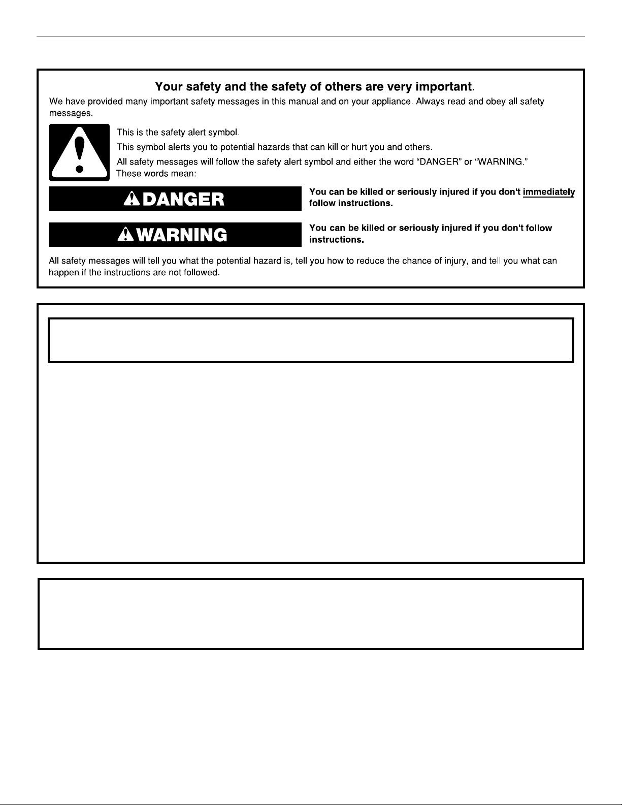
RANGE SAFETY
WARNING: If the information in these instructions is not followed exactly, a fire or
explosion may result causing property damage, personal injury or death.
– Do not store or use gasoline or other flammable vapors and liquids in the vicinity of this
or any other appliance.
– WHAT TO DO IF YOU SMELL GAS:
Do not try to light any appliance.
•
Do not touch any electrical switch.
•
Do not use any phone in your building.
•
Immediately call your gas supplier from a neighbor's phone. Follow the gas supplier's
•
instructions.
If you cannot reach your gas supplier, call the fire department.
•
– Installation and service must be performed by a qualified installer, service agency or
the gas supplier.
WARNING: Gas leaks cannot always be detected by smell.
Gas suppliers recommend that you use a gas detector approved by UL or CSA.
For more information, contact your gas supplier.
If a gas leak is detected, follow the “What to do if you smell gas” instructions.
2
Page 3
IMPORTANT: Do not install a ventilation system that blows air downward toward this gas cooking appliance. This type of
ventilation system may cause ignition and combustion problems with this gas cooking appliance resulting in personal injury or
unintended operation.
In the State of Massachusetts, the following installation instructions apply:
■ Installations and repairs must be performed by a qualified or licensed contractor, plumber, or gas fitter qualified or licensed by
the State of Massachusetts.
■ Acceptable Shut-off Devices: Gas Cocks and Ball Valves installed for use shall be listed.
■ A flexible gas connector, when used, must not exceed 4 feet (121.9 cm).
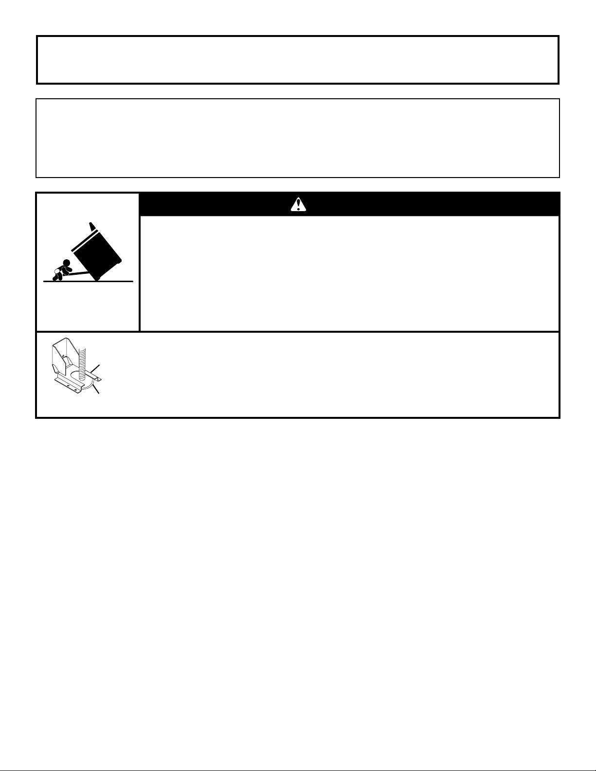
WARNING
Tip Over Hazard
A child or adult can tip the range and be killed.
Install anti-tip bracket to floor or wall per installation instructions.
Slide range back so rear range foot is engaged in the slot of the anti-tip bracket.
Re-engage the anti-tip bracket if the range is moved.
Do not operate range without anti-tip bracket installed and engaged.
Failure to follow these instructions can result in death or serious burns to children and adults.
Anti-Tip
Bracket
Range Foot
To verify the anti-tip bracket is installed and engaged:
• Slide range forward.
• Look for the anti-tip bracket securely attached to floor or wall.
Slide range back so rear range foot is under anti-tip bracket.•
• See installation instructions for details.
3
Page 4
INSTALLATION REQUIREMENTS
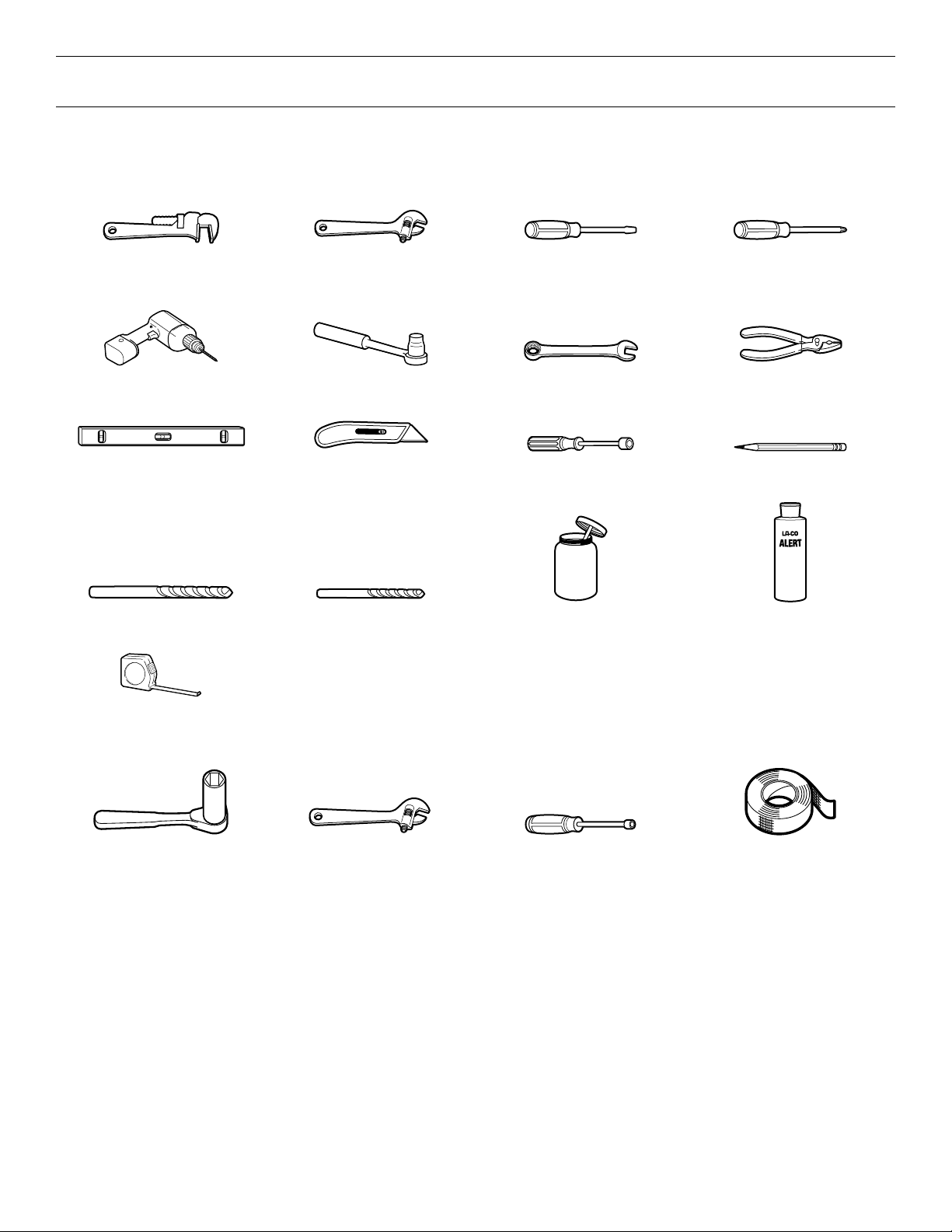
Tools and Parts
Gather the required tools and parts before starting installation. Read and follow the instructions provided with any tools listed here.
Tools Needed
Pipe wrench Adjustable wrench or
Drill 3/8" (95 mm) drive ratchet 15/16" (24 mm)
Level Tubing cutter 1/4" (6.4 mm), 3/8" (9.5 mm),
3/16" (4.8 mm) carbide tip
masonry bit
5/8" (16 mm) wrench
1/8" (3.2 mm) drill bit Pipe‑joint compound
1/8" x 41/4"
(3.2 mm x 108 mm)
flat‑blade screwdriver
combination wrench
5/16" (7.9 mm) nut drivers
resistant to Propane gas
#2 Phillips screwdriver
Pliers
Marker or pencil
Noncorrosive leak‑detection
solution
Tape measure
For Propane/Natural Gas Conversions
1/2" (13 mm) deep‑well
socket
Adjustable wrench 7 mm nut driver Masking tape
4
Page 5
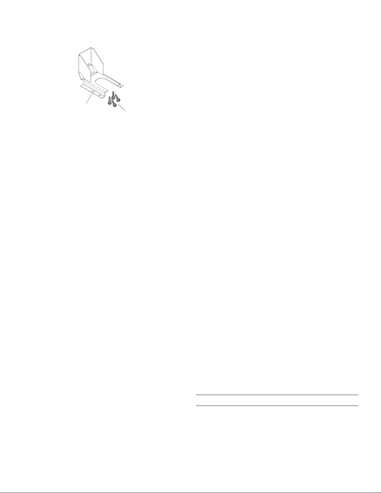
Parts Supplied
B
Check that all parts are included.
■ Anti-tip bracket kit
A
A. Anti-tip bracket
B. #8-18 x 1" (2.5 cm) Phillips head screws (4)
NOTE: Anti-tip bracket must be securely mounted to
subfloor. Thickness of flooring may require longer screws
to anchor bracket to subfloor. Longer screws are available
from your local hardware store. See the “Install Anti-Tip
Bracket” section.
■ Gas pressure regulator
■ Burner grates
■ Burner bases and burner caps
■ Grill grate (on grill models)
■ Wave tray (on grill models)
■ Flame spreader (on grill models)
■ Burner assembly (on grill models)
■ Grease trays (2) (on grill models)
■ Griddle drip tray (on griddle models)
■ Grill drip tray (on grill models)
■ Island trim
■ Propane orifice package (W10393255)
■ Conversion label (W10839411)
NOTE: The cooktop is manufactured for use with Natural gas.
To convert to Propane gas, see the “Gas Conversions” section.
Additional Parts Supplied on Steam‑Assist Models
■ Model W10049700 water filter kit
■ 1/4" (6.4 mm) to 1/4" (6.4 mm) water supply union
Parts Needed
■ Power supply cord kit:
■ 30" (76.2 cm) and 36" (91.4 cm) models: A UL Listed
40-amp power supply cord kit
■ 48" (121.9 cm) models: A UL Listed 50-amp power
supply cord kit marked for use with nominal 1
(3.5 cm) diameter connection openings
■ A UL Listed strain relief
■ UL Listed wire connectors
■ All models must be installed with a backguard if installing
at zero clearance to a combustible back wall surface such
as drywall. Alternatively, zero clearance to a back wall is
acceptable provided the surface of the entire back wall
above the range and below the hood is covered with a
non-combustible material such as tile or stainless steel.
See “Cabinet Dimensions” in the “Location Requirements”
section for installation requirements.
■ 30" (76.2 cm) Adjustable Backguard
Order Part Number 8285148
■ 36" (91.4 cm) Adjustable Backguard
Order Part Number 8284756
■ 48" (121.9 cm) Adjustable Backguard
Order Part Number 8284755
■ 9" (22.9 cm) Backguard for 30" (76.2 cm) Ranges
Order Part Number W10115773
■ 9" (22.9 cm) Backguard for 36" (91.4 cm) Ranges
Order Part Number W10115776
■ 9" (22.9 cm) Backguard for 48" (121.9 cm) Ranges
Order Part Number W10115777
■ 22" (55.9 cm) Backguard with Shelf for 30"
(76.2 cm) Ranges
Order Part Number W10225950
■ 22" (55.9 cm) Backguard with Shelf for 36"
(91.4 cm) Ranges
Order Part Number W10225949
■ 22" (55.9 cm) Backguard with Shelf for 48"
(121.9 cm) Ranges
Order Part Number W10225948
To order, see the “Assistance or Service” section of the Use
and Care Guide.
Additional Parts Needed on Steam‑Assist Models
■ Tubing staples/retainers
■ 1/4" (6.4 mm) outer diameter (O.D.) flexible
codes-approved water supply tubing
(to make water connection)
■ Water connection device (to connect 1/4" (6.4 mm) O.D.
tubing to water source). Check local codes for type of
connection required.
Check local codes and consult gas supplier. Check existing gas
supply and electrical supply. See the “Electrical Requirements”
and “Gas Supply Requirements” sections.
It is recommended that all electrical connections be made by
a licensed, qualified electrical installer.
3
/8"
High Altitude Conversion
To convert the cooktop for elevations above 6,560 ft (1,999.5 m),
order a High Altitude Conversion Kit.
■ Part Number W10394296: Propane gas high altitude
■ Part Number W10394295: Natural gas high altitude
To order, see the “Assistance or Service” section of the Use
and Care Guide.
5
Page 6
Location Requirements
E
E
IMPORTANT: Observe all governing codes and ordinances.
Do not obstruct flow of combustion and ventilation air.
■ It is the installer’s responsibility to comply with installation
clearances specified on the model/serial/rating plate. The
model/serial/rating plate is located under the console on
the right-hand side.
■ It is recommended that a 600 CFM (17.0 m
range hood be installed above the range.
■ It is not recommended that a microwave hood combination
be mounted above the range.
■ Recessed installations must provide complete enclosure
of the sides and rear of the range.
■ All openings in the wall or floor where range is to be installed
must be sealed.
■ Do not seal the range to the side cabinets.
■ Cabinet opening dimensions that are shown must be used.
Given dimensions are minimum clearances.
■ The anti-tip bracket must be installed. To install the anti-tip
bracket shipped with the range, see the “Install Anti-Tip
Bracket” section.
■ Grounded electrical supply is required. See the “Electrical
Requirements” section.
■ Proper gas supply connection must be available. See the
“Gas Supply Requirements” section.
■ Contact a qualified floor covering installer to check that
the floor covering can withstand at least 200°F (93°C). Use
an insulated pad or 1/4" (64 mm) plywood over carpet and
under range if installing range over carpeting.
IMPORTANT: To avoid damage to your cabinets, check with
your builder or cabinet supplier to make sure that the materials
used will not discolor, delaminate, or sustain other damage. This
oven has been designed in accordance with the requirements
of UL and CSA International and complies with the maximum
allowable wood cabinet temperatures of 194°F (90°C).
Mobile Home — Additional Installation Requirements
The installation of this range must conform to the Manufactured
Home Construction and Safety Standard, Title 24 CFR,
Part 3280 (formerly the Federal Standard for Mobile Home
Construction and Safety, Title 24, HUD Part 280). When such
standard is not applicable, use the Standard for Manufactured
Home Installations, ANSI A225.1/NFPA 501A or local codes.
In Canada, the installation of this range must conform with
the current standards CAN/CSA-A240-latest edition or with
local codes.
Mobile Home Installations Require:
When this range is installed in a mobile home, it must be
secured to the floor during transit. Any method of securing the
range is adequate as long as it conforms to the standards listed
above.
3
/hr) or larger
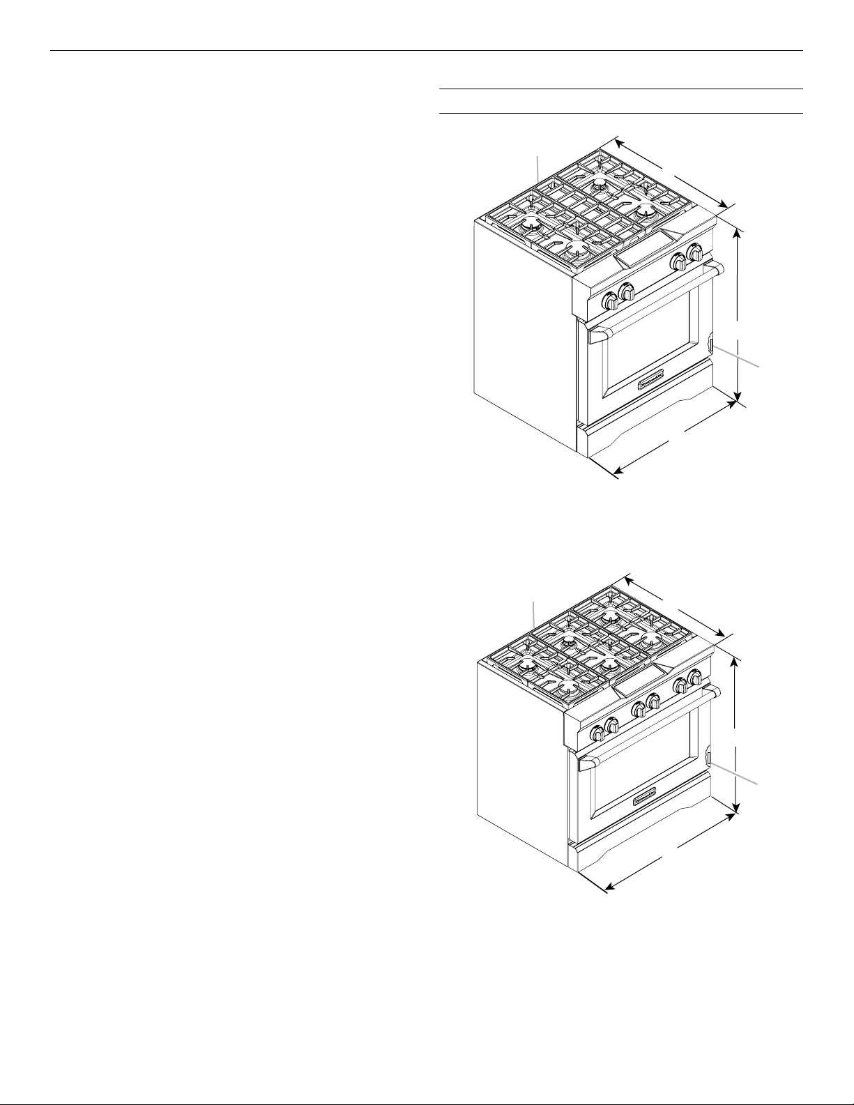
Product Dimensions
30" (76.2 cm) models
A
A. Optional backguard may be installed.
3
B. 27
/4" (70.5 cm) depth with control panel (See NOTE.)
3
C. 35
/4" (90.8 cm) cooktop height when sitting on the wheels
D. 30" (76.2 cm) width
E. Model/serial/rating plate location
36" (91.4 cm) models
A
B
C
D
B
C
D
A. Optional backguard may be installed.
3
B. 27
/4" (70.5 cm) depth with control panel (See NOTE.)
3
C. 35
/4" (90.8 cm) cooktop height when sitting on the
wheels
D. 36" (91.4 cm) width
E. Model/serial/rating plate location
6
Page 7
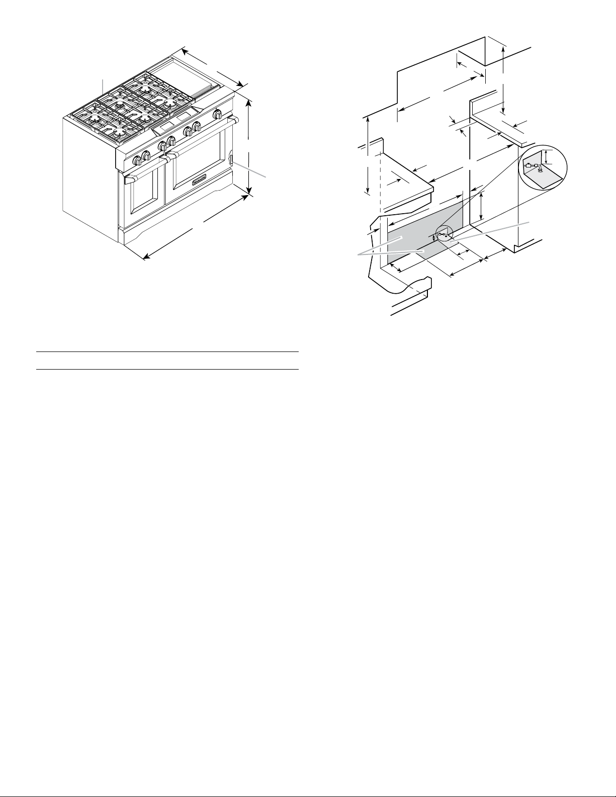
48" (121.9 cm) models
E
Electrical
installation
area*
installation
A
B
C
D
A. Optional backguard may be installed.
3
B. 27
/4" (70.5 cm) depth with control panel (See NOTE.)
3
C. 35
⁄4" (90.8 cm) cooktop height when sitting on the wheels
D. 48" (121.9 cm) width
E. Model/serial/rating plate location
NOTE: When installed in a 24" (61.0 cm) base cabinet with 25"
(63.5 cm) countertop; front of oven door protrudes 1
7
/8" (4.8 cm)
beyond 24" (61.0 cm) base cabinet.
Cabinet Requirements
Cabinet opening dimensions shown are for 25" (64.0 cm)
countertop depth, 24" (61.0 cm) base cabinet depth, and
36" (91.4 cm) countertop height. Dimensions must be met
in order to ensure a flush fit to back wall.
IMPORTANT: If installing a range hood or hood liner above
the range, follow the range hood or hood liner installation
instructions for dimensional clearances above the
cooktop surface.
C
**
D
B
O***
A
E
F
J
F
I
H
I
G
Gas
area
J
L
K
N
M
A. 18" (45.7 cm) upper cabinet to countertop
B. 30" (76.2 cm) model: 30" (76.2 cm) min. upper cabinet width
36" (91.4 cm) model: 36" (91.4 cm) min. upper cabinet width
48" (121.9 cm) model: 48" (121.9 cm) min. upper cabinet width
C. 13" (33 cm) max. upper cabinet depth
D. For minimum clearance to top of range**.
1
E. 30
/4" (76.8 cm) on 30" (76.2 cm) models
361/4" (92.1 cm) on 36" (91.4 cm) models
481/4" (122.6 cm) on 48" (121.9 cm) models
F. 6" (15.2 cm) min. clearance from both sides of range to side
wall or other combustible material
G. 15" (38.1 cm)
H. 22" (55.9 cm) on 30" (76.2 cm) models
28" (71.1 cm) on 36" (91.4 cm) models
40" (101.6 cm) on 48" (121.9 cm) models
1
I. 1
/2" (3.8 cm)
J. 3" (7.6 cm)
K. 5" (12.7 cm)
L. 6" (15.2 cm) on 30" (76.2 cm) models
14" (35.5 cm) on 36" (91.4 cm) models
24" (61.0 cm) on 48" (121.9 cm) models
1
M. 10
/2" (26.7 cm)
N. 6" (15.2 cm)
O. 6" (15.2 cm)***
* Receptacle must be rotated 90° for Canadian installation.
** Minimum Clearances
30" (76.2 cm) models: 30" (76.2 cm) minimum clearance
between the top of the cooking platform and the bottom of
an uncovered wood or metal cabinet
36" (91.4 cm) models: 42" (106.7 cm) minimum clearance
between the top of the cooking platform and the bottom of
an uncovered wood or metal cabinet
48" (121.9 cm) models: 42" (106.7 cm) minimum clearance
between the top of the cooking platform and the bottom of
an uncovered wood or metal cabinet
*** If the surface of the back wall is constructed of a combustible
material and a backguard is not installed, a 6" (15.2 cm)
minimum clearance is required for all models.
7
Page 8
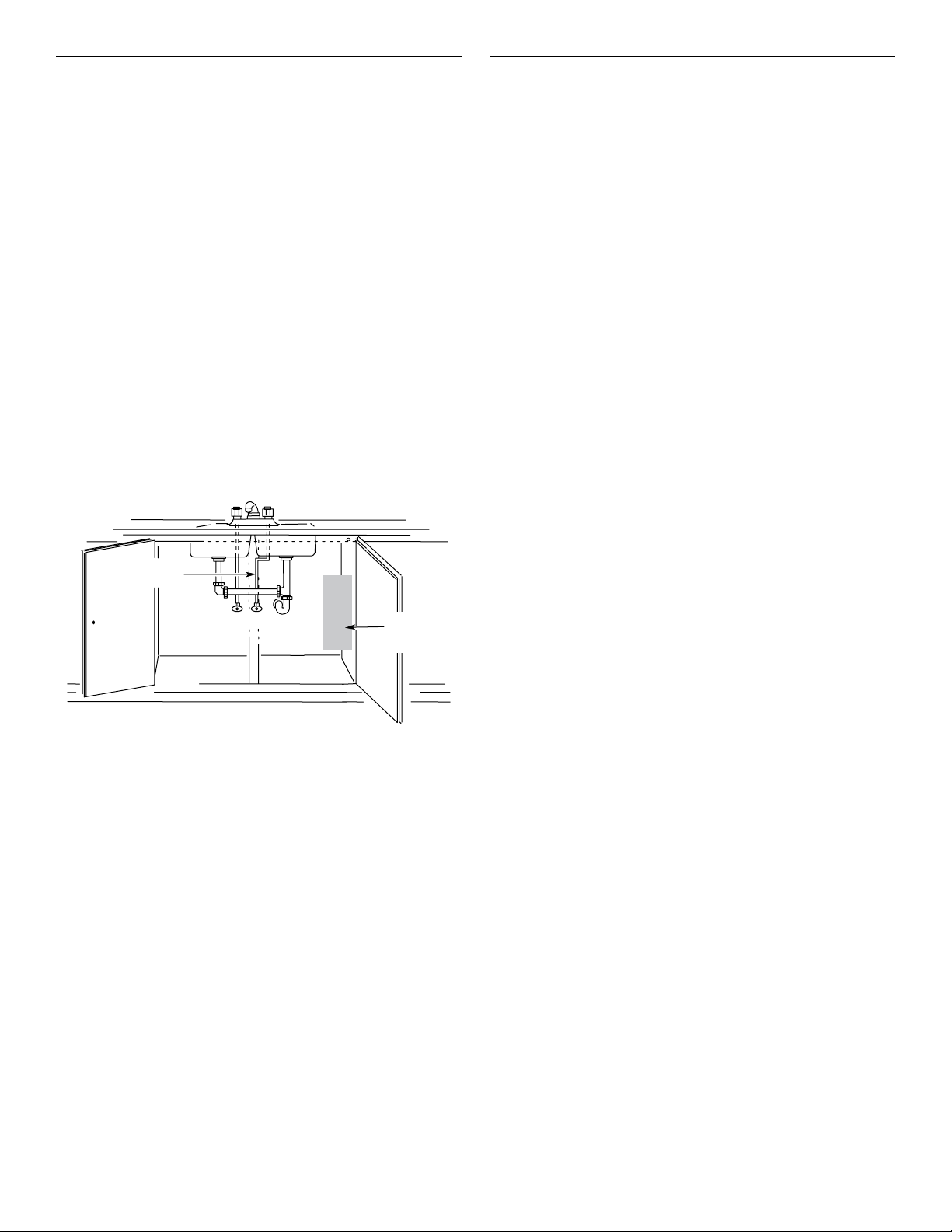
Water Filtration System
LocationRequirements
(on some models)
For best results, do not install the water filtration system outside
or in extreme hot or cold temperatures. Temperature of water
supply to the water filtration system must be between 40°F (4°C)
and 100°F (38°C). Do not install on hot water supply line.
Locate the water filtration system near the cold water supply
pipe under the kitchen sink to filter cold water.
Make sure that the water filter assembly is installed in the
upright position.
It will be necessary to drill a 1/2" (13 mm) minimum diameter
hole in the upper-right or left rear corner of the side wall of
the cabinet under the sink to route the water supply tubing
through to the range.
Depending on your installation configuration, more routing holes
may be required.
Coil enough flexible codes-approved water supply tubing
behind the range to allow for the connection to the range to
be made behind the range prior to setting the range in place.
Typical Installation Configuration
NOTE: For unique installations, contact a licensed plumber.
In Massachusetts, a licensed plumber is required and the
Commonwealth of Massachusetts Plumbing Code 248-CMR
will be adhered to.
Water Supply Requirements
A cold water supply with water pressure between 30 and
120 psi (207 and 827 kPa) is required to operate the steam
feature. In Massachusetts, plumbing code 248 CMR 3.00 and
10.00 must be followed, and a licensed plumber will be used.
If you have questions about your water pressure, call a licensed,
qualified plumber.
Reverse Osmosis Water Supply
IMPORTANT: The pressure of the water supply coming out of
a reverse osmosis system going to the water inlet valve of the
range needs to be between 30 and 120 psi (207 and 827 kPa).
If a reverse osmosis water filtration system is connected to your
cold water supply, the water pressure to the reverse osmosis
system needs to be a minimum of 40 psi (276 kPa).
If the water pressure to the reverse osmosis system is less than
40 psi (276 kPa):
■ Check to see whether the sediment filter in the reverse
osmosis system is blocked. Replace the filter, if necessary.
■ Allow the storage tank on the reverse osmosis system to refill
after heavy usage.
If you have questions about your water pressure, call a licensed,
qualified plumber.
Cold water
supply
Hot
Cold
Filter
assembly
location
8
Page 9
Electrical Requirements – U.S.A. Only
If codes permit and a separate ground wire is used, it is
recommended that a qualified electrical installer determine
that the ground path and wire gauge are in accordance with
local codes.
If codes permit and a separate ground wire is used, it is
recommended that a qualified electrician determine that
the ground path is adequate.
Do not use an extension cord.
Be sure that the electrical connection and wire size are adequate
and in conformance with the National Electrical Code, ANSI/
NFPA 70 — latest edition — and all local codes and ordinances.
A copy of the above code standards can be obtained from:
National Fire Protection Association
WARNING: Improper connection of the equipment-grounding
conductor can result in a risk of electric shock. Check with a
qualified electrician or service technician if you are in doubt as
to whether the appliance is properly grounded. Do not modify
the power supply cord plug. If it will not fit the outlet, have a
proper outlet installed by a qualified electrician.
Electrical Connection
To properly install your range, you must determine the type of
electrical connection you will be using and follow the instructions
provided for it here.
■ Range must be connected to the proper electrical voltage
and frequency as specified on the model/serial/rating plate.
The model/serial/rating plate is located under the console
on the right-hand side. Refer to the illustrations in “Product
Dimensions” in the “Location Requirements” section.
■ This range may be manufactured with a 4-wire power
supply cord or may not include a power supply cord. If your
range does not include a power supply cord, use a 4-wire
power supply cord rated at 250 volts, 40 or 50 amps, and
investigated for use with ranges.
Range Rating*
120/240 Volts 120/208 Volts Amps Range Size
8.8–16.5 kW 7.8–12.5 kW 40 or 50** 30" (76.2 cm),
16.6–22.5 kW 12.6–18.5 kW 50 48" (121.9 cm)
* The NEC calculated load is less than the total connected load
listed on the model/serial/rating plate.
** If connecting to a 50-amp circuit, use a 50-amp rated cord
with kit. For 50-amp rated cord kits, use kits that specify use
with a nominal 1
■ A circuit breaker is recommended.
■ Wire sizes and connections must conform with the rating
of the range.
■ The Tech Sheet is located behind the kick plate in a clear
plastic bag.
1 Batterymarch Park
Quincy, MA 02169-7471
Specified Rating of Power
Supply Cord Kit and
Circuit Protection
36" (91.4 cm)
3
/8" (3.49 cm) diameter connection opening.
If connecting to a 4‑wire system:
This range is manufactured with the ground connected to the
cabinet. The ground must be revised, so the green ground wire
of the 4-wire power supply cord is connected to the cabinet.
See the “Electrical Connection – U.S.A. Only” section.
Grounding through the neutral conductor is prohibited for
new branch-circuit installations (1996 NEC), mobile homes,
recreational vehicles, or an area where local codes prohibit
grounding through the neutral conductor.
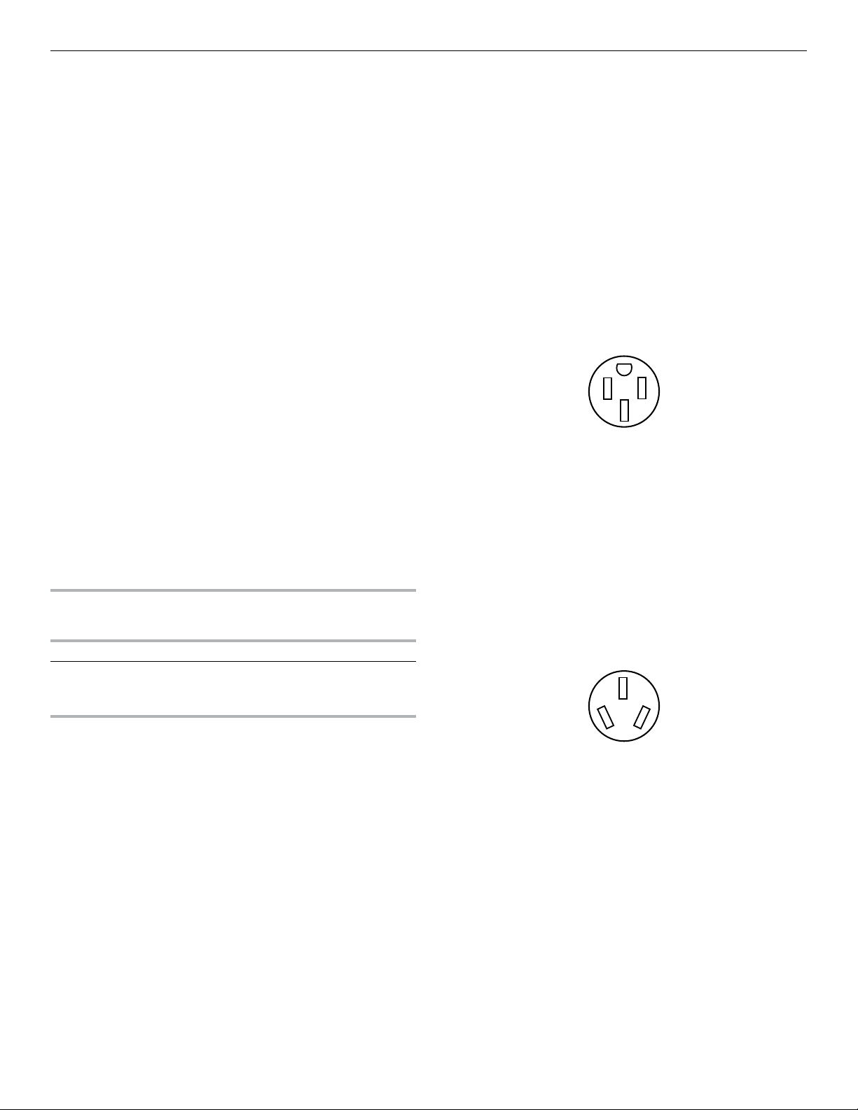
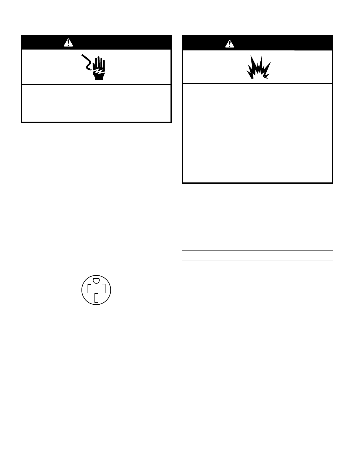
When a 4-wire receptacle of NEMA Type 14-50R is used, a
matching UL Listed, 4-wire, 250-volt, 40- or 50-amp, range
power supply cord must be used. This cord contains four copper
conductors with ring terminals or open-end spade terminals
with upturned ends, terminating in a NEMA Type 14-50R plug
on the supply end.
The fourth (grounding) conductor must be identified by a green
or green/yellow cover and the neutral conductor by a white
cover. Cord should be Type SRD or SRDT with a UL Listed strain
relief and be at least 4 ft (1.22 m) long.
4-wire receptacle
The minimum conductor sized for the copper 4-wire power
cord are:
40-amp circuit
2 No.-8 conductors
1 No.-10 white neutral
1 No.-10 green grounding
If connecting to a 3‑wire system:
Local codes may permit the use of a UL Listed, 3-wire, 250-volt,
40- or 50-amp range power supply cord (pigtail). This cord
contains three copper conductors with ring terminals or openend spade terminals with upturned ends, terminating in a NEMA
Type 10-50P plug on the supply end. Connectors on the
appliance end must be provided at the point the power supply
cord enters the appliance. This uses a 3-wire receptacle of
NEMA Type 10-50R.
3-wire receptacle (10-50R)
9
Page 10
Electrical Requirements – CanadaOnly
Gas Supply Requirements
WARNING
Electrical Shock Hazard
Electrically ground range.
Failure to do so can result in death, fire, or
electrical shock.
If codes permit and a separate ground wire is used, it is
recommended that a qualified electrical installer determine
that the ground path and wire gauge are in accordance with
local codes.
Be sure that the electrical connection and wire size are adequate
and in conformance with the CSA Standard C22.1, Canadian
Electrical Code, Part 1 — latest edition, and all local codes
and ordinances.
A copy of the above code standards can be obtained from:
Canadian Standards Association
178 Rexdale Blvd.
Toronto, ON M9W 1R3 CANADA
■ Check with a qualified electrical installer if you are not sure
the range is properly grounded.
■ When a 4-wire, single-phase 250-volt, 60 Hz., AC-only
electrical supply is available, a 40-amp minimum circuit
protection is required on 30" (76.2 cm) and 36" (91.4 cm)
ranges and a 50-amp minimum circuit protection is required
on 48" (121.9 cm) ranges, fused on both sides of the line.
■ A time-delay fuse or circuit breaker is recommended.
■ This range is equipped with a CSA International Certified
Power Cord intended to be plugged into a standard 14-50R
wall receptacle. Be sure the wall receptacle is within reach of
range’s final location.
■ Do not use an extension cord.
WARNING
Explosion Hazard
Use a new CSA International approved gas supply line.
Install a shut-off valve.
Securely tighten all gas connections.
If connected to propane, have a qualified person make
sure gas pressure does not exceed 14" (36 cm) water
column.
Examples of a qualified person include:
licensed heating personnel,
authorized gas company personnel, and
authorized service personnel.
Failure to do so can result in death, explosion, or fire.
Observe all governing codes and ordinances.
IMPORTANT: This installation must conform with all local codes
and ordinances. In the absence of local codes, installation
must conform with American National Standard, National Fuel
Gas Code ANSI Z223.1 — latest edition — or CAN/CGA B149
— latest edition.
IMPORTANT: Range must be connected to a regulated
gas supply.
IMPORTANT: Leak testing of the range must be conducted
according to the manufacturer’s instructions.
Type of Gas
Natural Gas:
The model/serial rating plate located on the right vertical surface
of the oven door frame has information on the types of gas that
can be used. If the types of gas listed do not include the type of
gas available, check with the local gas supplier.
Propane Gas conversion:
Conversion must be done by a qualified service technician.
No attempt shall be made to convert the range cooktop from
the gas specified on the model/serial/rating plate for use with
a different gas without consulting the serving gas supplier.
To convert to Propane gas, use the Propane gas conversion
kit provided with your range and see the “Gas Conversions”
section. The parts for this kit are in the package containing
literature supplied with the range.
10
Page 11
Gas Supply Line
A
C
Gas Pressure Regulator
■ Provide a gas supply line of 3/4" (19 mm) rigid pipe to the
cooktop location. A smaller size pipe on longer runs may
result in insufficient gas supply. With Propane gas, piping
or tubing size can be 1/2" (13 mm) minimum. Usually,
Propane gas suppliers determine the size and materials
used in the system.
NOTE: Pipe-joint compounds that resist the action of
Propane gas must be used. Do not use TEFLON
®†
tape.
Flexible metal appliance connector:
■ If local codes permit, a new CSA design-certified, 4-5 ft
(122-152 cm) long, 5/8" (16 mm) or 3/4" (19 mm) I.D.,
flexible metal appliance connector may be used for
connecting the cooktop to the gas supply line.
■ A 1/2" (13 mm) male pipe thread is needed for
connection to the female pipe threads of the inlet to the
appliance pressure regulator.
■ Do not kink or damage the flexible metal tubing when
moving the cooktop.
IMPORTANT: All connections must be wrench-tightened.
Do not make connections to the gas regulator too tight.
Making the connections too tight may crack the regulator
and cause a gas leak. Do not allow the regulator to turn or
move when tightening fittings.
■ Must include a shut-off valve:
Install a manual gas line shut-off valve in an easily accessible
location. Do not block access to shut-off valve. The valve is
for turning on or shutting off gas to the cooktop.
B
A. Gas supply line
B. Shut-off valve open position
C. To cooktop
The gas pressure regulator supplied with this cooktop must
be used. The inlet pressure to the regulator should be as
follows for proper operation:
Natural Gas:
Minimum pressure: 15.2 cm WCP
Maximum pressure: 35.6 cm WCP
Propane Gas:
Minimum pressure: 27.9 cm WCP
Maximum pressure: 35.6 cm WCP
Contact local gas supplier if you are not sure about the
inlet pressure.
Burner Input Rating — Altitude
Input ratings shown on the model/serial/rating plate are for
elevations up to 2,000 ft (609.6 m).
For elevations above 2,000 ft (609.6 m), ratings need to be
reduced at a rate of 4% for each 1,000 ft (304.8 m) above
sea level (not applicable for Canada).
Gas Supply Pressure Testing
Gas supply pressure for testing regulator must be at least 2.5 cm
water column pressure above the manifold pressure shown on
the model/serial/rating plate.
Line pressure testing above 1/2 psi (3.5 kPa) gauge
(35.6 cm WCP)
The cooktop and its individual shut-off valve must be
disconnected from the gas supply piping system during any
pressure testing of that system at test pressures in excess of
1/2 psi (3.5 kPa).
Line pressure testing at 1/2 psi (3.5 kPa) gauge
(35.6 cm WCP) or lower
The cooktop must be isolated from the gas supply piping
system by closing its individual manual shut-off valve during
any pressure testing of the gas supply piping system at test
pressures equal to or less than 1/2 psi (3.5 kPa).
†®TEFLON is a registered trademark of Chemours.
11
Page 12
INSTALLATION INSTRUCTIONS
B
Unpack the Range
WARNING
Excessive Weight Hazard
Use two or more people to move and install range.
Failure to do so can result in back or other injury.
1. Remove shipping materials, tape, and film from range.
Keep shipping pallet under range. Remove oven racks,
grates, and parts package from inside oven.
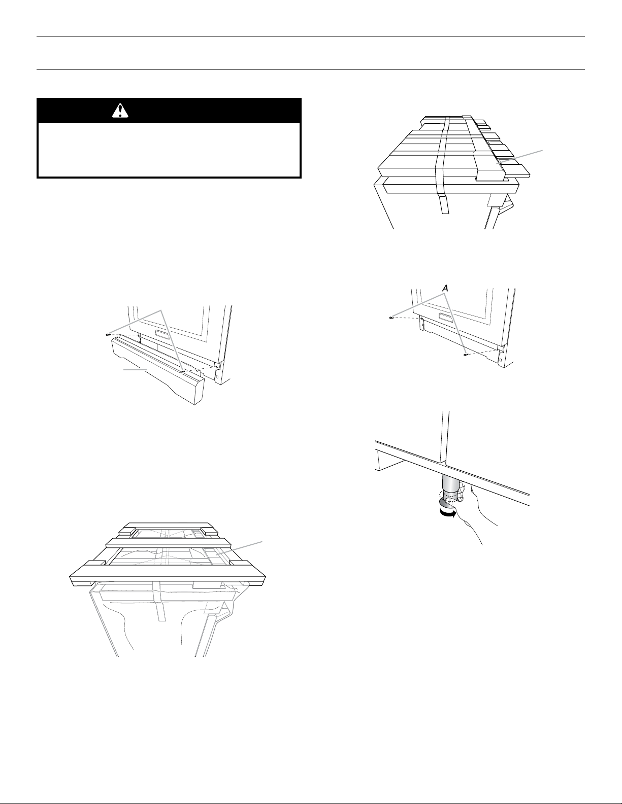
2. Remove kick plate.
Your range will either have the kick plate already installed
(follow Option 1) or packaged on top of the unit (follow
Option 2).
Option 1
a. Remove foam between door and kick plate.
b. Remove screws from kick plate.
Packaging removed
A
A. Kick plate
b. Lay kick plate to the side to avoid scratching the
stainless steel.
c. Remove screws from range.
A
A. Kick plate
B. Remove these screws.
c. Lift up on kick plate to release plate from shoulder
screws.
d. Lay kick plate to the side to avoid scratching the
stainless steel.
Option 2
a. Remove kick plate from top of range and grate pack.
In packaging
A
A. Remove these screws.
3. For 48" (121.9 cm) models only, rotate center support
counterclockwise off the pallet until it stops.
NOTE: This support is used only for shipping and is not
needed for installation.
4. Lay a piece of cardboard from side packaging on the floor
behind range. Using two or more people, firmly grasp
each side of range. Lift range up about 3" (8.0 cm) and
move it back until range is off shipping pallet. Set range
on cardboard to avoid damaging floor.
12
A. Kick plate
Page 13
Install Optional Backguard
C
B
A
B
A
All ranges may require a backguard. See “Cabinet Dimensions”
in the “Location Requirements” section. See the “Tools and
Parts” section for information on ordering.
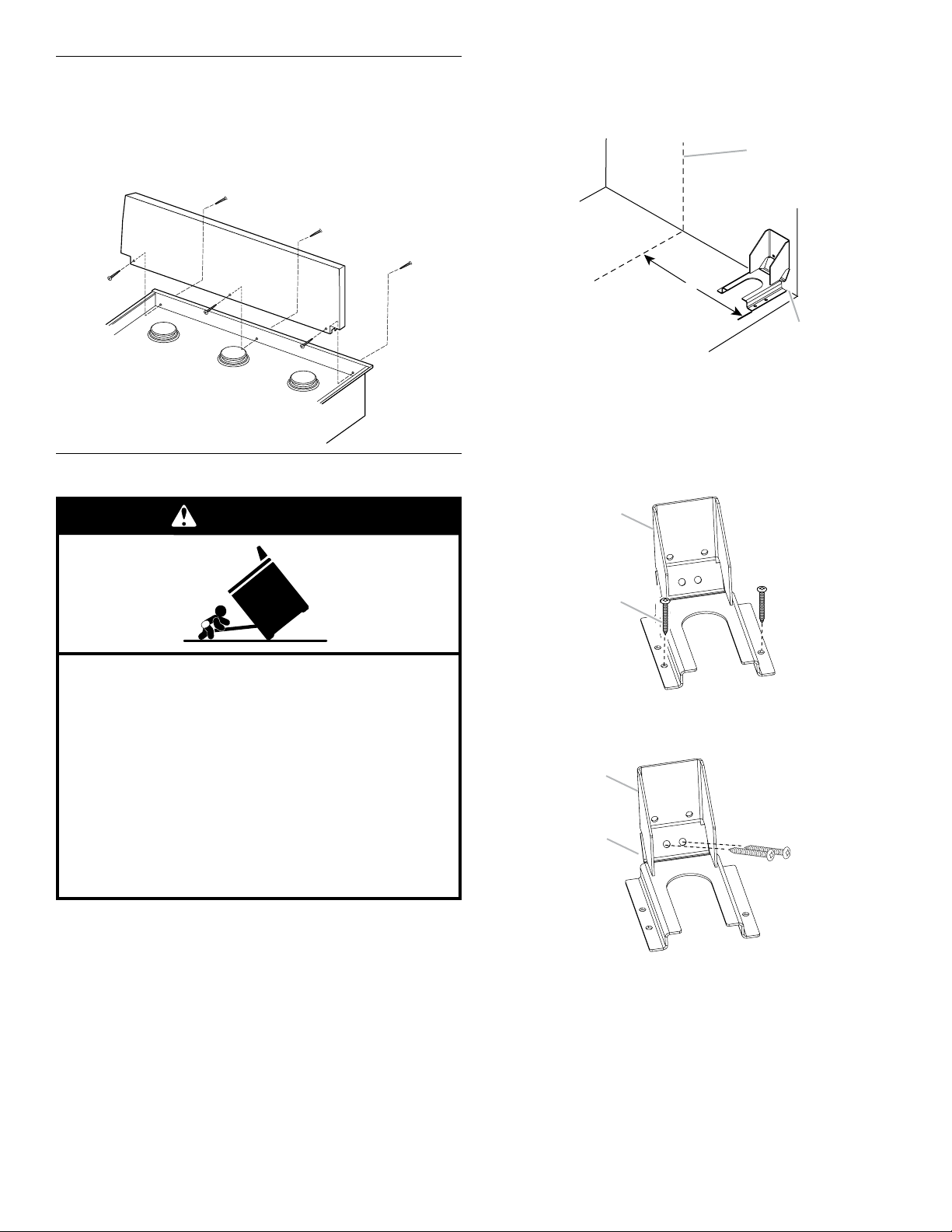
Remove island trim and attach backguard using six screws.
Insert three from the front and three from the back (9" [22.9 cm]
backguard shown).
Install Anti-Tip Bracket
Measurement C:
Optional distance from back wall. If back wall is constructed
of a combustible material and a backguard is not installed, a
6" (15.2 cm) minimum clearance is required for all models.
Install anti-tip bracket accordingly.
A
B
A. Centerline
B. Centerline of cutout to outside
edge of anti-tip bracket
C. Back wall to back of range
3. Drill two 1/8" (3.0 mm) holes that correspond to the bracket
holes of the determined mounting method. See the following
illustrations.
Floor Mounting
WARNING
Tip Over Hazard
A child or adult can tip the range and be killed.
Install anti-tip bracket to floor or wall per installation
instructions.
Wall Mounting
Slide range back so rear range foot is engaged in the
slot of the anti-tip bracket.
Re-engage anti-tip bracket if range is moved.
Do not operate range without anti-tip bracket installed
and engaged.
Failure to follow these instructions can result in death
or serious burns to children and adults.
1. Determine which mounting method to use: floor or wall.
If you have a stone or masonry floor, you can use the
wall mounting method.
2. Determine and mark centerline of the cutout space. The
mounting bracket must be installed on the right side of the
cutout. Position mounting bracket in cutout as shown in the
following illustration.
Measurement B:
30" (76.2 cm) ranges: 14
36" (91.4 cm) ranges: 17
48" (121.9 cm) ranges: 23
1
⁄4" (36.1 cm)
1
⁄4" (43.8 cm)
3
⁄8" (59.3 cm)
4. Using a Phillips screwdriver, mount anti-tip bracket
to the wall or floor with the two #12 x 1
screws provided.
Depending on the thickness of your flooring, longer screws
may be necessary to anchor the bracket to the subfloor.
Longer screws are available from your local hardware store.
5. Move range close enough to opening to allow for electrical
connections to be made. Remove shipping base, cardboard,
or hardboard from under range.
6. Continue installing your range using the following
installation instructions.
A. #12 x 15⁄8" (4.1 cm) screws
B. Anti-tip bracket
A. #12 x 15⁄8" (4.1 cm) screws
B. Anti-tip bracket
5
⁄8" (4.1 cm)
13
Page 14
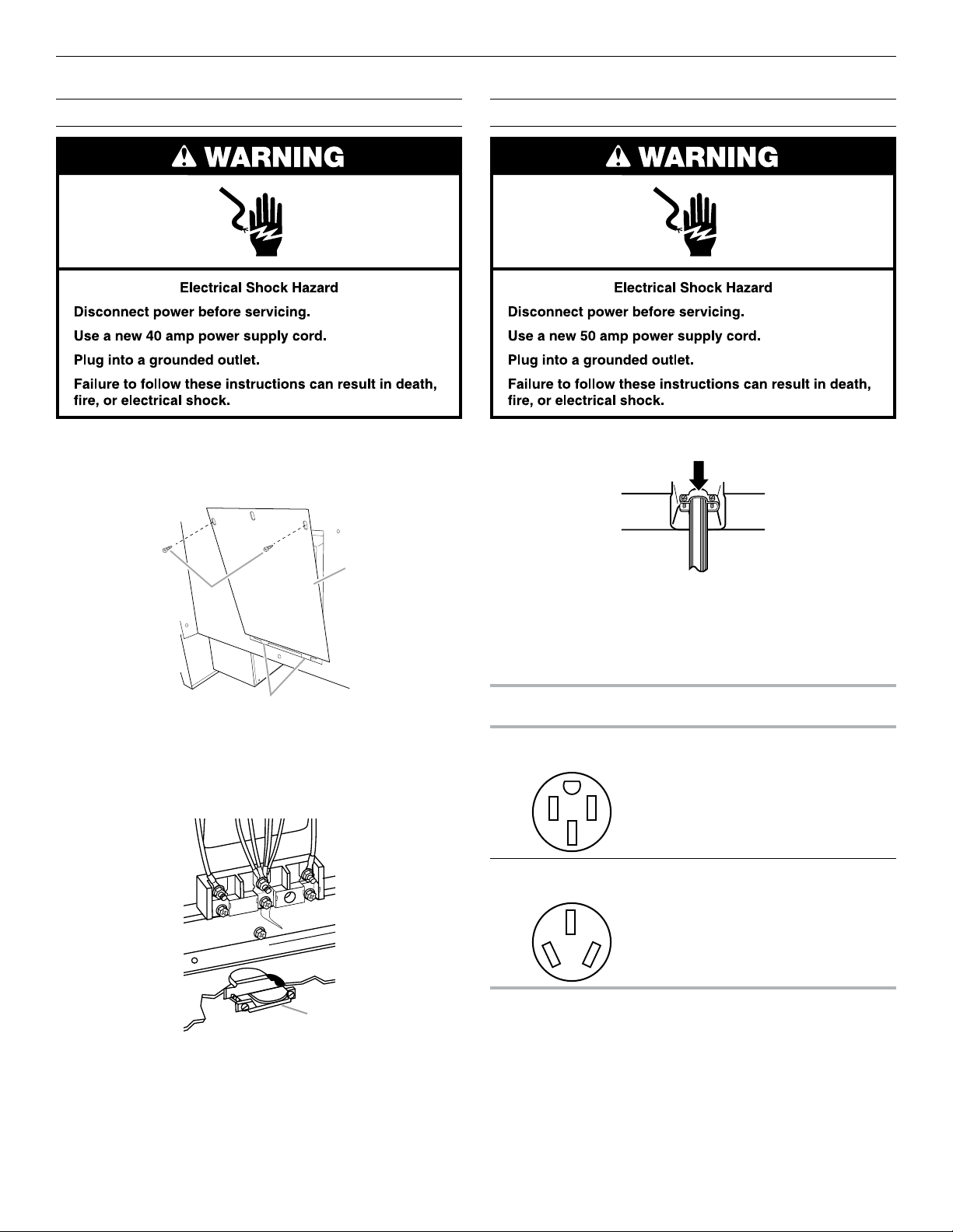
Electrical Connection – U.S.A. Only
B
C
30" (76.2 cm) and 36" (91.4 cm) Models 48" (121.9 cm) Models
1. Disconnect power.
2. Remove the terminal block cover screws and disengage
mounting tabs to remove terminal block cover from back
of range.
A
A. Phillips head screws
B. Terminal block cover
C. Two mounting tabs at bottom
3. Add power supply cord strain relief.
■ Assemble a UL Listed strain relief in the opening.
■ Tighten strain-relief screw against the power supply cord.
4. Complete installation following instructions for your type
of electrical connection:
4‑wire (recommended)
3‑wire (if 4-wire is not available)
Electrical Connection Options
If your home has:
4-wire receptacle
(NEMA type 14-50R)
3-wire receptacle
(NEMA type 10-50R)
And you will be
connecting to:
A UL Listed,
250-volt minimum,
40- or 50-amp,
range power supply
cord
A UL Listed,
250-volt minimum,
40- or 50-amp,
range power supply
cord
Go to
section:
4-Wire
Connection:
Power Supply
Cord
3-Wire
Connection:
Power Supply
Cord
14
A
A. UL Listed strain relief
Page 15
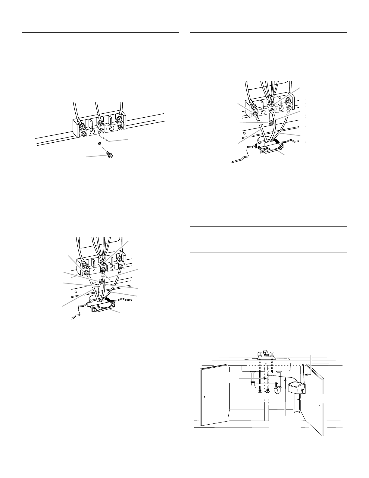
4‑Wire Connection: Power Supply Cord
A
A
B
E
F
G
H
C
Water supply
3‑Wire Connection: Power Supply Cord
Use this method for:
■ New branch-circuit installations (1996 NEC)
■ Mobile homes
■ Recreational vehicles
■ In an area where local codes prohibit grounding through
the neutral
1. Remove the ground-link screw from the range frame. Save
the ground-link screw. Bend the ground link away from the
range so that it does not contact the range.
B
A. Ground-link screw
B. Ground link bent away from range
2. Connect the green ground wire from the power supply
cord to the range using the ground-link screw. The ground
wire must be attached first and must not contact any other
terminal.
3. Use a 1/4" (64 mm) nut driver to remove the hex washer
head screws from the terminal blocks.
4. Connect the neutral (center) wire to the center terminal
connector using one of the hex washer head screws.
Securely tighten screw for proper electrical connection.
D
Use this method only if local codes permit connecting cabinetground conductor to neutral wire of power supply cord.
1. Use a 1/4" (64 mm) nut driver and remove the hex washer
head screws from the aluminum terminal blocks.
2. Connect the neutral (center) wire to the center terminal
connector using one of the hex washer head screws.
Securely tighten screw for proper electrical connection.
D
E
B
F
A
G
A. Line 1
B. Ground link
C. Hex washer head screw
D. Silver-colored terminal
block screw
E. Neutral (center) wire
F. Line 2
G. UL Listed strain relief
and 40- or 50-amp
range power supply cord
3. Connect the other two wires (lines 1 and 2) to the outer
terminal screws on the terminal block.
4. Tighten strain-relief screws.
5. Replace terminal block cover.
Install Water Filtration System
(on some models)
Install Model W10049700 Water Filter
C
1. Install the water filter near the cold water supply pipe under
the kitchen sink to filter the cold water.
IMPORTANT: Be sure to allow a minimum clearance of
1
/2" (3.8 cm) under the filter system for removing the
1
filter cartridge.
Make sure that the water filter assembly is installed
in the upright position.
A. Line 1
B. Green ground wire
C. Ground-link screw
D. Hex washer head screw
E. Silver-colored terminal
block screw
I
F. Ground link
G. Neutral (center) wire
H. Line 2
I. UL Listed strain relief
and 40- or 50-amp
range power supply cord
Typical Installation Configuration
NOTE: For unique installations, contact a licensed plumber.
In Massachusetts, a licensed plumber is required and the
Commonwealth of Massachusetts Plumbing Code 248-CMR
will be adhered to.
line to oven
5. Connect the other two wires (lines 1 and 2) to the outer
aluminum terminal blocks.
6. Securely tighten screws for proper electrical connection.
7. Tighten strain-relief screws.
8. Replace terminal block cover.
Cold water
supply
Hot
Cold
Water supply
line to cold
water supply
Filter
Assembly
15
Page 16

2. Attach the supplied water filter mounting ring and screw
Mounting ring and scre
A
B
A
W
suppl
connection
R
at the recommended location.
3. Attach filter to the mounting ring.
w
If you need to release tubing:
Push in collet to release tubing. With collet held in, pull tubing
straight out.
A. Collet
1½" (3.8 cm) clearance
Connect to Home Water Supply
1. Make connection to the cold water supply line.
■ A leak-tight connection to the 1/4" (6.4 mm) flexible
codes-approved water supply line must be provided.
■ Check local codes for type of connection required.
■ Flexible codes-approved water supply line must be
cut with a tubing cutter so the ends are concentric
and without burrs.
NOTE: It is recommended that the cold water line be soft water.
Connect to Water Filter Inlet (yellow)
NOTE: Use the quick-connect stem and/or elbow adapter
fittings in the combination needed for your installation
configuration.
1. Attach the supplied 3/8" (9.5 mm) to 1/4" (6.4 mm) stem
or 3/8" (9.5 mm) to 1/4" (6.4 mm) elbow quick-connect
adapter fitting to the yellow water filter inlet connection
by pushing the quick-connect fitting past the O-ring until
you hit the backstop.
Connect to Water Filter Outlet (blue)
1. Attach the supplied 3/8" (9.5 mm) to 1/4" (6.4 mm) stem
or 3/8" (9.5 mm) to 1/4" (6.4 mm) elbow quick-connect
adapter fitting to the blue water filter outlet connection by
pushing the quick-connect fitting past the O-ring until you
hit the backstop.
2. Connect another piece of flexible codes-approved water
supply line to the quick-connect adapter fitting you just
installed on the filter outlet (blue) side of the water filter.
3. Pull tube to ensure it is secured.
Water supply tubing to range
Sink
ater
y
Yellow
WATER
IN
Blue
WATE
OUT
Shutoff
valve
Water supply tubing
to cold water supply
Filter
2. Connect the flexible codes-approved water supply line
(not provided) from the home cold water supply pipe to
the quick-connect adapter fitting you just installed on
the filter inlet (yellow) side of the water filter.
3. Pull tube to ensure it is secured.
A
16
A. Quick-connect elbow adapter fitting
B. Quick-connect stem adapter fitting
B
A. 1/4" (6.4 mm) water supply tubing
B. O-ring
C. Backstop
4. Route flexible codes-approved water supply line
through under-sink cabinet and oven cabinet cutout.
C
Page 17

5. Connect the flexible codes-approved water supply line
B
F
A
FG
A
B
to the range copper tubing, using a 1/4" (6.4 mm) to
1/4" (6.4 mm) water supply union.
C
A
A. To home water supply
B. Rear of cabinet cutout
C. Flexible codes-approved water supply
line from home water supply
D. 1/4" (6.4 mm) to 1/4" (6.4 mm) water
supply union (supplied in water filter kit)
E. Oven copper tubing
F. Range front
6. Turn on water supply.
7. Check all connections for leaks.
NOTE: No flushing or conditioning of the water filter is required
prior to use.
D
E
Make Gas Connection
3. Attach one adapter to the gas pressure regulator and
the other adapter to the gas shut-off valve. Tighten both
adapters, being certain not to move or turn the gas pressure
regulator.
4. Use a 15/16" (24 mm) combination wrench and an adjustable
wrench to attach the flexible gas supply to the adapters.
Check that connector is not kinked.
IMPORTANT: All connections must be wrench-tightened.
Do not make connections to the gas regulator too tight. Making
the connections too tight may crack the regulator and cause a
gas leak. Do not allow the regulator to turn or move when
tightening fittings.
B
C
A. Gas pressure regulator
B. Use pipe-joint compound.
C. Adapter (must have 1/2"
[13 mm] male pipe thread)
D. Flexible connector
D
E
H
E. Manual gas shut-off valve
F. 1/2" (13 mm) or
3/4" (19 mm) gas pipe
G. Use pipe-joint compound.
H. Adapter
Complete Connection
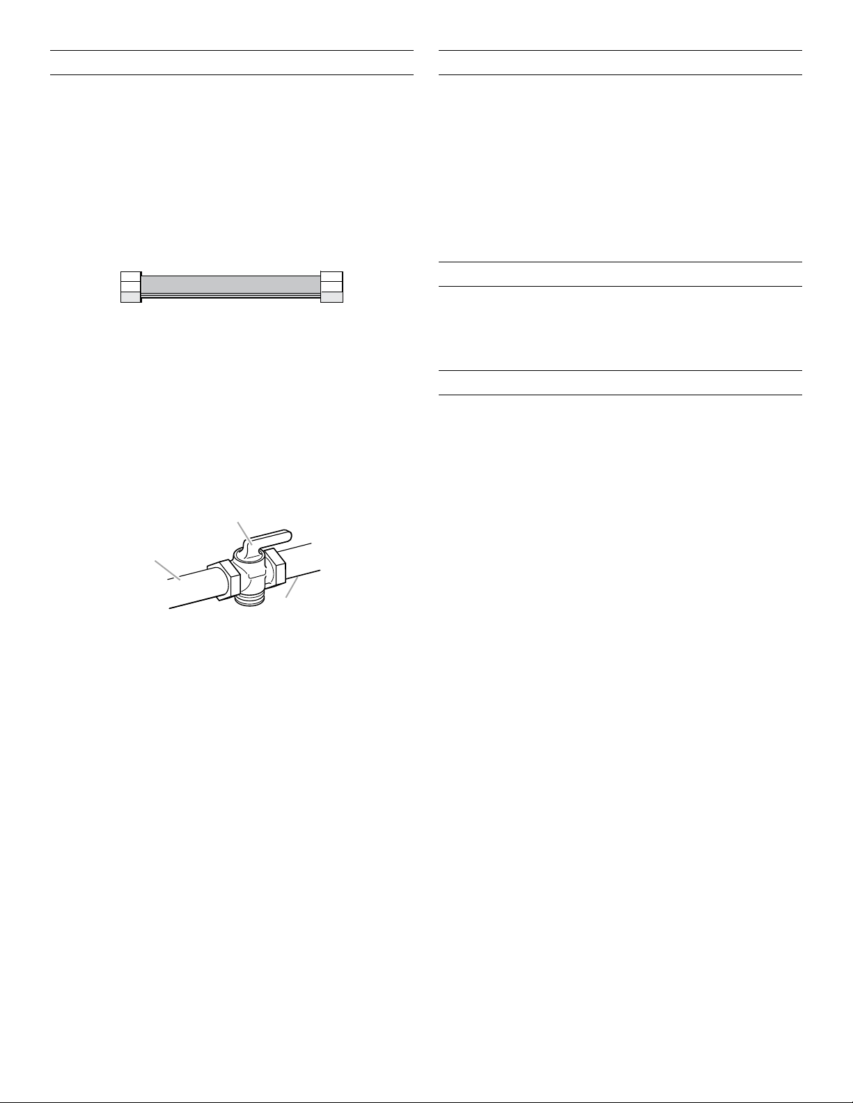
1. Open the manual shut-off valve in the gas supply line. The
valve is open when the handle is parallel to the gas pipe.
WARNING
Explosion Hazard
Use a new CSA International approved gas supply line.
Install a shut-off valve.
Securely tighten all gas connections.
If connected to propane, have a qualified person make
sure gas pressure does not exceed 14" (36 cm) water
column.
Examples of a qualified person include:
licensed heating personnel,
authorized gas company personnel, and
authorized service personnel.
Failure to do so can result in death, explosion, or fire.
1. Assemble flexible connector from gas supply pipe to
pressure regulator located in the middle rear of the range.
2. Apply pipe-joint compound made for use with Propane gas
to the smaller thread ends of the flexible connector adapters.
(See B and G in the following illustration.)
A. Closed valve
B. Open valve
2. Test all connections by brushing on an approved
noncorrosive leak-detection solution. If bubbles appear,
a leak is indicated. Correct any leak found.
3. Remove cooktop burner caps, burner bases, and grates
from parts package. Place burner bases on cooktop. Place
burner caps on burner bases. Place grates over burners
and caps.
4. Check that the range is plugged into the appropriate
grounded outlet. (See the “Electrical Requirements” section.)
5. Turn on power supply. For further information, please refer
to the user instructions located in the Use and Care Guide.
Verify Anti-Tip Bracket Location
1. Using a 5/16" (7.9 mm) socket or wrench, turn all four
leveling rods one full turn to raise the range and provide
enough clearance for the rear leveling leg to slide into the
anti-tip bracket.
2. Move range into its final location, making sure rear leveling
leg slides into anti-tip bracket.
3. Use a flashlight to look underneath the bottom of the range
and visually check that the rear range foot is inserted into
the slot of the anti-tip bracket.
17
Page 18

Level Range
A
B
A
B
A
A
A
A
C
D
NOTE: Range must be level for satisfactory baking performance.
1. Place rack in oven.
2. Place level on rack and check levelness of the range, first
side to side, then front to back.
3. If range is not level, adjust the leveling rods. Turn leveling
rods located behind the kick plate to level range and to raise
or lower range to the desired countertop height.
NOTE: All roller feet must be off the floor upon final installation.
B
2. Cut and remove tie strap from rear of burner assembly.
A. Tie strap
3. Lift burner assembly up and out to remove.
4. Slide drip tray into opening on the right front side of the grill
basin. There are guides to assure correct placement of the
drip tray.
A
A. Rear leveling rod
B. Front and brass leveling rod
Install Grill Grease Trays
(on grill models)
1. Remove flame spreader. Pull forward slightly on the flame
spreader to release the tabs from the rear slots and lift out.
A. Grill front
B. Rear tabs and slots
A. Drip tray
5. Insert the large grease tray all the way under the back edge
of the grill basin and hook it into the slots.
B
A. Large grease tray
B. Slots
6. Insert the small grease tray all the way under the front of the
grill basin and hook it into the slots.
When the two grease trays are installed properly, the small
grease tray will hook over the large grease tray.
B
A. Large grease tray
18
B. Grease tray connection
C. Small grease tray
D. Slots
Page 19

7. Insert the orifice tube on the front of the burner assembly
A
B
A
B
A
A
into the opening at the front of the grill basin and set burner
assembly into place.
A
A. Front opening
8. Insert front tabs of the flame spreader into slots at the front
of the grill basin, then the rear tabs into the rear slots.
Electronic Ignition System
Install Burner Bases and Burner Caps
Install the burner base, making sure the igniter electrode is
properly aligned with the base. Place burner caps on top
of burner bases. If burner caps are not properly positioned,
surface burners will not light.
Ultra Power™ Dual‑Flame Burner
A. Incorrect
B. Correct
Professional Burner
A. Incorrect
B. Correct
B
Simmer/Melt Burner
A. Front tabs and slots
B. Rear tabs and slots
9. Check the surface burner and grill flames. Refer to the
“Electronic Ignition System” section.
10. Place the wave tray on top of the flame spreader.
11. Place the grill grate into position.
Install Griddle
(on griddle models)
The griddle is factory installed.
1. Place drip tray in the well at the front of the griddle. Slide tray
toward the back until it stops.
A
B
A. Griddle drip tray
B. Griddle
2. Clean griddle before using. Refer to the Use and Care Guide.
A. Incorrect
B. Correct
B
Initial Lighting and Gas Flame Adjustments
Cooktop burners use electronic igniters in place of standing
pilots. When the cooktop control knob is turned to any position,
the system creates a spark to light the burner. This sparking
continues until the flame is lit or the knob is turned to OFF.
NOTE: The first time igniting the burners will take longer. This
allows the gas to reach the burners during the first use.
Check Operation of Cooktop Burners
Push in and turn each control knob to LITE.
NOTE: You will hear a clicking sound while the line clears.
The surface burners and grill flames should light within
4 seconds. The first time a burner is lit, it may take longer
than 4 seconds to light because of air in the gas line.
After verifying the proper burner operation, turn the control
knobs to OFF.
If burners do not light properly:
■ Turn cooktop control knob to OFF.
■ Check that the cooktop is plugged in and the circuit breaker
has not tripped or the fuse has not blown.
■ Check that the gas shut-off valves are set to the
open position.
■ Check that burner caps are properly positioned on
burner bases.
Repeat start-up. If a burner does not light at this point, contact
your dealer or authorized service company for assistance.
19
Page 20

Flame Height
A
B
A
A
A
B
The cooktop flame should be a steady blue flame approximately
1/4" (6.4 mm) high.
Dual Flame Burner
7. Put a control knob onto the valve stem of the burner
you want to adjust.
A. Upper (simmer) flame
B. Lower flame
Single Flame Burner
To Adjust Flame Height:
1. Unplug range or disconnect power.
2. Remove burner grates.
3. Remove the control knobs.
4. Open the oven door and remove the two screws on each
side of the range that hold the control console in place.
NOTE: Make sure to leave oven door open or the control
console will not rest in the side brackets properly once it
is detached.
5. Pull up on the control console and let it drop forward into
the notched console brackets on each side.
8. Turn the control knob to LO and, using a butane extension
lighter, light the burner.
9. Remove the control knob.
10. Use a 1/8" x 4
1
/4" (3.2 mm x 108 mm) flat-blade screwdriver
to adjust the flame height. Tighten screw to reduce flame
height. Loosen screw to increase flame height.
NOTE: When you are converting to Propane gas, the screw
should be tightened down completely on the single-output
valves. The dual-output valve should not be adjusted.
B
A. Single flame burner adjustment screw (on right side of valve)
B. Dual flame burner adjustment screw (on left side of valve)
11. When finished adjusting the flame height, put a control knob
back onto the valve stem and turn off the burner.
12. Remove the control knob.
13. Replace the round gasket.
14. Repeat steps 6 through 13 for any other burners that
need adjustment.
15. Lift up on the control console and set it back into place.
For a proper fit, the flange of the control console must hook
over the lip on the front of the range cooktop.
A. Control console bracket
6. Remove the round gasket from the valve stem.
A. Control console flange
B. Front lip of range cooktop
20
Page 21

16. Check that the control console is flush with the top edge
A
B
of the range.
A. Flush with range top
17. Replace the two screws on each side of the control console.
18. Replace the control knobs.
19. Replace burner grates.
20. Test the flame by turning the control from LO to HI,
checking the flame at each setting.
Reinstall Kick Plate
1. Align shoulder screw mounting holes with shoulder screws
on range.
2. Push kick plate down against front of range until the top
screw holes are aligned with the mounting holes on the front
of the range.
3. Reattach screws to the top of the kick plate.
C
A
Complete Installation
1. Check that all parts are now installed. If there is an
extra part, go back through the steps to see which
step was skipped.
2. Check that you have all of your tools.
3. Dispose of/recycle all packaging materials.
4. For oven use and cleaning, read the Use and Care Guide.
Check Operation of Oven(s)
1. Turn power on.
2. Start a Bake cycle. See the Use and Care Guide for
operating instructions.
If oven(s) does not operate, check the following:
■ Household fuse is intact and tight or circuit breaker
has not tripped.
■ Electrical supply is connected.
■ See the “Troubleshooting” section in the Use and
Care Guide.
3. When oven has been on for 10–15 minutes, open the oven
door and feel for heat.
If you do not feel heat or if an error code (“F” followed by
a number plus “E” followed by a number) appears in the
display, turn off the oven and contact a qualified technician.
4. Touch OFF.
To set the clock and other oven functions, refer to the Use
and Care Guide.
If you need Assistance or Service:
Please reference the “Assistance or Service” section of the
Use and Care Guide or contact the dealer from whom you
purchased your range.
D
A. Kick plate
B. Reattach these screws.
C. Top screw hole
D. Shoulder screw mounting hole
21
Page 22

GAS CONVERSIONS
A
B
C
IMPORTANT: Gas conversions from Natural gas to Propane gas
must be done by a qualified installer.
Propane Gas Conversion
WARNING
Explosion Hazard
Use a new CSA International approved gas supply line.
Install a shut-off valve.
Securely tighten all gas connections.
If connected to propane, have a qualified person make
sure gas pressure does not exceed 14" (36 cm) water
column.
Examples of a qualified person include:
licensed heating personnel,
authorized gas company personnel, and
authorized service personnel.
Failure to do so can result in death, explosion, or fire.
WARNING
Tip Over Hazard
A child or adult can tip the range and be killed.
Install anti-tip bracket to floor or wall per installation
instructions.
Slide range back so rear range foot is engaged in the
slot of the anti-tip bracket.
Re-engage anti-tip bracket if range is moved.
Do not operate range without anti-tip bracket installed
and engaged.
Failure to follow these instructions can result in death
or serious burns to children and adults.
1. Turn the manual shut-off valve to the closed position.
A. To range
B. Shut-off valve (closed position)
C. Gas supply line
2. Unplug range or disconnect power.
22
Page 23

To Convert Gas Pressure Regulator
A
A
B
C
A
B
CDE
A
A
Convert Surface Burners
1. Remove the access cap by using a wrench, turning
the access cap counterclockwise.
2. Remove spring retainer from the cap by pushing against the
flat side of the spring retainer. Look at the spring retainer to
locate the “NAT” or “LP” position. Turn over the spring
retainer so the “LP” is showing on the bottom. Snap the
spring retainer back into the cap. Reinstall the cap onto
the regulator.
A
B
A. Access cap
B. Gasket
C. Gas pressure regulator
D. LP position
E. NAT position
3. Test the gas pressure regulator and gas supply line.
The regulator must be checked at a minimum 2.5 cm water
column above the set pressure. The inlet pressure to the
regulator should be as follows for operation and checking
the regulator setting:
Propane Gas:
Minimum pressure: 27.9 cm WCP
Maximum pressure: 35.6 cm WCP
Gas Supply Pressure Testing
Gas supply pressure for testing regulator must be at least
2.5 cm water column pressure above the manifold pressure
shown on the model/serial/rating plate.
Line pressure testing above 1/2 psi (3.5 kPa) gauge
(35.6 cm WCP)
The range and its individual shut-off valve must be
disconnected from the gas supply piping system during
any pressure testing of that system at test pressures in
excess of 1/2 psi (3.5 kPa).
Line pressure testing at 1/2 psi (3.5 kPa) gauge
(35.6 cm WCP) or lower
The range must be isolated from the gas supply piping
system by closing its individual manual shut-off valve during
any pressure testing of the gas supply piping system at test
pressures equal to or less than 1/2 psi (3.5 kPa).
1. If the burner grates are installed, remove them.
2. Remove burner cap.
3. Remove the burner base.
B
Large Dual Burner
A. Burner cap
B. Burner base
Medium Burner
A. Burner cap
B. Burner base
C. Choke (for use with medium
burner, Propane gas only)
Small Burner
A. Burner cap
B. Burner base
4. Apply masking tape to the end of a 7 mm nut driver to help
hold the gas orifice spud in the nut driver while changing it.
Insert nut driver into the gas opening, and press down onto
the gas orifice spud, then remove by turning the gas orifice
spud counterclockwise and lifting out. Set gas orifice spud
aside.
5. Replace with correct Propane gas orifice spud. See the
“Propane Gas Orifice Spud/Hood Chart.”
Use the following chart to find the exact orifice spud
placement.
Fully insert choke into bottom of medium burner base.
Choke should snap into place.
Propane Gas Orifice Spud/Hood Chart
Burner
Rating
3,000
BTUs
11,000
BTUs
14,000
BTUs
Color Size Burner Style
Blue 0.55 mm Small burners
Yellow 0.97 mm Medium burners
Choke
Red/Green 1.05 mm
0.35 mm
Large burner – main
Larger burner – simmer
14,500
Black 1.18 mm Grill burner
BTUs
Burner orifice spud
A. Size stamp or color
Grill orifice hood
A. Size stamp
23
Page 24

6. Place Natural gas orifice in plastic parts bag for future use,
A
A
B
A
B
C
and keep with package containing literature.
NOTE: There may be extra orifices in your kit.
7. Replace the burner base.
8. Replace burner cap.
9. Repeat steps 2 through 8 for the remaining burners.
To Convert Grill Burner (on some models)
1. Remove grill grate, wave plate, flame spreader and burner
assembly. See “Install Grill Grease Trays” section for removal
instructions. Set parts aside.
2. Use a 1/2" (13 mm) deep-well socket to remove the Natural
gas orifice hood. Replace with correct grill Propane gas
orifice hood. See “Propane Gas Orifice Spud/Hood Chart.”
A. Grill orifice hood location
3. Turn Propane gas orifice hood down tightly onto orifice base.
4. Place Natural gas orifice hoods in plastic parts bag for future
use and keep with package containing literature.
5. Before replacing the burner assembly, loosen the screw at
the front of the burner and rotate the shutter so that the
opening is 5/16" (8 mm) wide.
Natural Gas Conversion
WARNING
Tip Over Hazard
A child or adult can tip the range and be killed.
Install anti-tip bracket to floor or wall per installation
instructions.
Slide range back so rear range foot is engaged in the
slot of the anti-tip bracket.
Re-engage anti-tip bracket if range is moved.
Do not operate range without anti-tip bracket installed
and engaged.
Failure to follow these instructions can result in death
or serious burns to children and adults.
1. Turn the manual shut-off valve to the closed position.
A. Shutter opening
B. Screw
6. Reinstall the burner assembly, flame spreader, wave plate,
and grill grate. See the “Install Grill Grease Trays” section for
installation instructions.
7. Open shut-off valve in the gas supply line. The valve is open
when the handle is parallel to the gas pipe.
REMEMBER: Once you have completed converting the
grill, test the range for leaks by brushing on an approved
noncorrosive leak-detection solution. Bubbles will show,
indicating a leak. Correct any leaks found.
8. Plug in range or reconnect power.
Complete Installation
1. Refer to the “Make Gas Connection” section for properly
connecting the range to the gas supply.
2. Refer to the “Electronic Ignition System” section for proper
burner ignition, operation, and burner flame adjustments.
IMPORTANT: You may have to adjust the Lo setting for each
cooktop burner.
Checking for proper cooktop burner flame is very important.
The small inner cone should have a very distinct blue flame
1/4" (6.4 mm) to 1/2" (13 mm) long. The outer cone is not as
distinct as the inner cone. Propane gas flames have a slightly
yellow tip.
3. Refer to “Complete Installation” in the “Installation
Instructions” section of this manual to complete
this procedure.
A. To range
B. Shut-off valve (closed position)
C. Gas supply line
2. Unplug range or disconnect power.
24
Page 25

To Convert Gas Pressure Regulator
A
A
B
C
A
B
CDE
A
A
Convert Surface Burners
1. Remove the access cap by using a wrench, turning
the access cap counterclockwise.
2. Remove spring retainer from the cap by pushing against the
flat side of the spring retainer. Look at the spring retainer to
locate the “LP” or “NAT” position. Turn over the spring
retainer so the “NAT” is showing on the bottom. Snap the
spring retainer back into the cap. Reinstall the cap onto
the regulator.
A
B
A. Access cap
B. Gasket
C. Gas pressure regulator
D. NAT position
E. LP position
3. Test the gas pressure regulator and gas supply line.
The regulator must be checked at a minimum 2.5 cm water
column above the set pressure. The inlet pressure to the
regulator should be as follows for operation and checking
the regulator setting:
Natural Gas:
Minimum pressure: 15.2 cm WCP
Maximum pressure: 35.6 cm WCP
Gas Supply Pressure Testing
Gas supply pressure for testing regulator must be at least
2.5 cm water column pressure above the manifold pressure
shown on the model/serial/rating plate.
Line pressure testing above 1/2 psi (3.5 kPa) gauge
(35.6 cm WCP)
The range and its individual shut-off valve must be
disconnected from the gas supply piping system during
any pressure testing of that system at test pressures in
excess of 1/2 psi (3.5 kPa).
Line pressure testing at 1/2 psi (3.5 kPa) gauge
(35.6 cm WCP) or lower
The range must be isolated from the gas supply piping
system by closing its individual manual shut-off valve during
any pressure testing of the gas supply piping system at test
pressures equal to or less than 1/2 psi (3.5 kPa).
1. If the burner grates are installed, remove them.
2. Remove burner cap.
3. Remove the burner base.
B
Large Dual Burner
A. Burner cap
B. Burner base
Medium Burner
A. Burner cap
B. Burner base
C. Choke (for use with medium
burner, Propane gas only)
Small Burner
A. Burner cap
B. Burner base
4. Apply masking tape to the end of a 7 mm nut driver to help
hold the gas orifice spud in the nut driver while changing it.
Insert nut driver into the gas opening, and press down onto
the gas orifice spud, then remove by turning the gas orifice
spud counterclockwise and lifting out. Set gas orifice spud
aside.
5. Replace with correct Natural gas orifice spud. See the
“Natural Gas Orifice Spud/Hood Chart.”
Use the following chart to find the exact orifice spud
placement.
Remove choke from medium burner base.
Natural Gas Orifice Spud/Hood Chart
Burner Rating Size Burner Style
5,000 BTUs 1.01 mm Small burners
15,000 BTUs 1.75 mm Medium burners
Choke
20,000 BTUs 2.10 mm
0.52 mm
Large burner – main
Large burner – simmer
18,000 BTUs 1.93 mm Grill burner
Burner orifice spud
A. Size stamp
Grill orifice hood
A. Size stamp
25
Page 26

6. Place Propane gas orifice in plastic parts bag for future use,
A
A
B
and keep with package containing literature.
NOTE: There may be extra orifices in your kit.
7. Replace the burner base.
8. Replace burner cap.
9. Repeat steps 2 through 8 for the remaining burners.
10. Replace burner grates.
To Convert Grill Burner (on some models)
1. Remove grill grate, wave plate, flame spreader and burner
assembly. See the “Install Grill Grease Trays” section for
removal instructions. Set parts aside.
2. Use a 1/2" (13 mm) deep-well socket to remove the Propane
gas orifice hood. Replace with correct grill Natural gas orifice
hood. See “Natural Gas Orifice Spud/Hood Chart.”
A. Grill orifice hood location
3. Turn Natural gas orifice hood down tightly onto orifice base.
4. Place Propane gas orifice hoods in plastic parts bag for
future use and keep with package containing literature.
5. Before replacing the burner assembly, loosen the screw at
the front of the burner and rotate the shutter so that the
opening is 3/8" (9.0 mm) wide.
6. Reinstall the burner assembly, flame spreader, wave plate,
and grill grate. See the “Install Grill Grease Trays” section for
installation instructions.
7. Open shut-off valve in the gas supply line. The valve is open
when the handle is parallel to the gas pipe.
REMEMBER: Once you have completed converting the
grill, test the range for leaks by brushing on an approved
noncorrosive leak-detection solution. Bubbles will show,
indicating a leak. Correct any leaks found.
8. Plug in range or reconnect power.
Complete Installation
1. Refer to the “Make Gas Connection” section for properly
connecting the range to the gas supply.
2. Refer to the “Electronic Ignition System” section for proper
burner ignition, operation, and burner flame adjustments.
IMPORTANT: You may have to adjust the Lo setting for each
cooktop burner.
Checking for proper cooktop burner flame is very important.
The small inner cone should have a very distinct blue flame
1/4" (6.4 mm) to 1/2" (13 mm) long. The outer cone is not as
distinct as the inner cone. Propane gas flames have a slightly
yellow tip.
3. Refer to “Complete Installation” in the “Installation
Instructions” section of this manual to complete
this procedure.
A. Shutter opening
B. Screw
26
Page 27

SÉCURITÉ DE LA CUISINIÈRE
AVERTISSEMENT : Si les renseignements dans ces instructions ne sont pas
exactement observés, un incendie ou une explosion peut survenir, causant des
dommages au produit, des blessures ou un décès.
– Ne pas entreposer ni utiliser de l’essence ou d’autres vapeurs ou liquides inflammables
à proximité de cet appareil ou de tout autre appareil électroménager.
– QUE FAIRE DANS LE CAS D’UNE ODEUR DE GAZ :
Ne pas tenter d’allumer un appareil.
•
Ne pas toucher à un commutateur électrique.
•
Ne pas utiliser le téléphone se trouvant sur les lieux.
•
Appeler immédiatement le fournisseur de gaz à partir du téléphone d'un voisin. Suivre
•
ses instructions.
À défaut de joindre votre fournisseur de gaz, appeler les pompiers.
•
– L’installation et l’entretien doivent être effectués par un installateur qualifié, une agence
de service ou le fournisseur de gaz.
27
Page 28

IMPORTANT : Ne pas installer un système de ventilation avec évacuation de l'air vers le bas, qui évacuerait l'air vers cet
appareil de cuisson à gaz. Ce type de système de ventilation peut causer des problèmes d'allumage et de combustion avec cet
appareil de cuisson à gaz et entraîner des blessures corporelles ou le fonctionnement non désiré de cet appareil.
Dans l’État du Massachusetts, les instructions d’installation suivantes sont applicables :
■ Les travaux d’installation et réparation doivent être exécutés par un plombier ou tuyauteur qualifié ou licencié, ou par le
personnel qualifié d’une entreprise licenciée par l’État du Massachusetts.
■ Remplacer par des dispositifs de fermeture acceptables : Les robinets de gaz et robinets à bille installés pour l'utilisation
devraient être indiqués.
■ Si un conduit de raccordement flexible est utilisé, sa longueur ne doit pas dépasser 4 pi (121,9 cm).
AVERTISSEMENT
Risque de basculement
Un enfant ou une personne adulte peut faire basculer la cuisinière ce qui peut causer un décès.
Joindre la bride antibasculement au pied arrière de la cuisinière.
Joindre de nouveau la bride antibasculement si la cuisinière est déplacée.
Voir détails dans les instructions d'installation.
Le non-respect de ces instructions peut causer un décès ou des brûlures graves aux enfants et
aux adultes.
La bride
antibasculement
Le pied de la cuisinière
Assurez-vous qu'une bride antibasculement est installée :
• Glisser la cuisinière vers l'avant.
• Vérifier que la bride antibasculement est bien fixée au plancher ou au mur.
• Glisser de nouveau la cuisinière vers l'arrière de sorte que le pied est sous la bride
antibasculement.
28
Page 29

EXIGENCES D’INSTALLATION
Outillage et pièces
Rassembler les outils et pièces nécessaires avant d’entreprendre l’installation. Lire et suivre les instructions fournies avec chacun des
outils de la liste ci-dessous.
Outils nécessaires
Clé à tuyauterie Clé à molette ou clé
Perceuse Clé à cliquet de 3/8" (95 mm) Clé mixte de 15/16" (24 mm) Pince
Niveau Coupe‑tube Tourne‑écrou de
Foret à maçonnerie à pointe
carburée de 3/16" (4,8 mm)
de 5/8" (16 mm)
Foret de 1/8" (3,2 mm) Composé d’étanchéité
Tournevis à lame
plate de 1/8" x 4
(3,2 mm x 108 mm)
1/4" (6,4 mm), 3/8" (9,5 mm),
5/16" (7,9 mm)
des raccords filetés –
résistant au gaz propane
1
/4"
Tournevis Phillips n° 2
Marqueur ou crayon
Solution non corrosive
de détection des fuites
Mètre‑ruban
Pour conversions pour gaz propane/naturel
Douille longue de 1/2"
(13 mm)
Clé à tuyauterie Tourne‑écrou de 7 mm Mètre‑ruban
29
Page 30

Pièces fournies
B
Vérifier que toutes les pièces sont présentes.
■ Trousse de bride antibasculement
A
A. Bride antibasculement
B. Quatre vis à tête Phillips n° 8-18 x 1" (2,5 cm)
REMARQUE : La bride antibasculement doit être solidement
fixée au sous-plancher. La profondeur du plancher peut
nécessiter des vis plus longues pour l’ancrage de la bride
dans le sous-plancher. Des vis plus longues sont disponibles
auprès de votre quincaillerie locale. Voir la section
“Installation de la bride antibasculement”.
■ Détendeur
■ Grilles de brûleur
■ Têtes et chapeaux de brûleurs
■ Plateau d’égouttement de la plaque à frir e (sur modèles
avec plaque à frire)
■ Plateau ondulé (sur modèles avec gril)
■ Répartiteur de flammes (sur modèles avec gril)
■ Burner assembly (sur modèles avec gril)
■ Grease trays (2) (sur modèles avec gril)
■ Griddle drip tray (sur modèles avec plaque à frire)
■ Grill drip tray (sur modèles avec gril)
■ Garniture d’îlot
■ Ensemble de gicleurs pour gaz propane (W10393255)
■ Étiquette de conversion (W10839411)
REMARQUE : La table de cuisson est conçue pour une
utilisation au gaz naturel. Pour effectuer une conversion au gaz
propane, voir la section “Conversions pour changement de gaz”.
Pièces supplémentaires fournies avec les modèles
à injection de vapeur
■ Ensemble de filtre à eau modèle W10049700
■ Raccord d’alimentation en eau de 1/4" (6,4 mm) par
1/4" (6,4 mm)
Pièces nécessaires
■ Ensemble de cordon d’alimentation électrique :
■ Modèles de 30" (76,2 cm) et 36" (91,4 cm) : Un ensemble
de cordon d’alimentation homologué de UL 40 ampères
■ Modèles de 48" (121,9 cm) : Un ensemble de cordon
d’alimentation homologué UL de 50 ampères compatible
avec des ouvertures de raccord de diamètre nominal de
3
/8" (3,5 cm)
1
■ Un serre-câble homologué UL
■ Connecteurs de fils (homologation UL)
■ Tous les modèles doivent être installés avec un dosseret
si l’installation se fait sans dégagement entre l’appareil et
une paroi arrière combustible comme un mur en gypse.
Une installation sans dégagement est permise si la totalité
de la surface de la paroi au-dessus et au-dessous de
la hotte est couverture d’un matériau non combustible,
comme des carreaux de céramique ou de l’acier inoxydable.
Voir “Dimensions du placard” à la section “Exigences
d’emplacement” pour les spécifications concernant
l’installation.
■ Dosseret rétractable de 30" (76,2 cm)
Commander la pièce numéro 8285148
■ Dosseret rétractable de 36" (91,4 cm)
Commander la pièce numéro 8284756
■ Dosseret rétractable de 48" (121,9 cm)
Commander la pièce numéro 8284755
■ Dosseret de 9" (22,9 cm) pour cuisinières de 30"
(76,2 cm)
Commander la pièce numéro W10115773
■ Dosseret de 9" (22,9 cm) pour cuisinières de 36"
(91,4 cm)
Commander la pièce numéro W10115776
■ Dosseret de 9" (22,9 cm) pour cuisinières de 48"
(121,9 cm)
Commander la pièce numéro W10115777
■ Dosseret de 22" (55,9 cm) pour cuisinières à tablette
de 30" (76,2 cm)
Commander la pièce numéro W10225950
■ Dosseret de 22" (55,9 cm) pour cuisinières à tablette
de 36" (91,4 cm)
Commander la pièce numéro W10225949
■ Dosseret de 22" (55,9 cm) pour cuisinières à tablette
de 48" (121,9 cm)
Commander la pièce numéro W10225948
Pour commander, voir la section “Assistance ou service”
du Guide d’utilisation et d’entretien.
Pièces supplémentaires nécessaires pour les modèles
à injection de vapeur
■ Agrafes/attaches de tuyau
■ Tuyau d’alimentation flexible homologué par les codes
en vigueur de diamètre externe de 1/4" (6,4 mm)
(pour la réalisation du raccordement en eau)
■ Dispositif de raccordement de l’eau (pour raccorder
le tuyau de diamètre externe de 1/4" (6,4 mm)
à l’alimentation en eau). Vérifier les codes locaux pour
connaître le type de raccordement exigé.
Vérifier les codes locaux et consulter le fournisseur de gaz.
Vérifier l’alimentation en gaz et l’alimentation électrique
existantes. Voir les sections “Spécifications électriques”
et “Spécifications de l’alimentation en gaz”.
Il est recommandé de faire réaliser tous les raccordements
électriques par un électricien qualifié agréé.
Conversion pour utilisation en haute altitude
Pour convertir la table de cuisson pour des altitudes
supérieures à 6 560 pi (1 999,5 m), commander un ensemble
pour conversion en haute altitude.
■ Pièce numéro W10394296 : gaz propane pour haute altitude
■ Pièce numéro W10394295 : gaz naturel pour haute altitude
Pour commander, voir la section “Assistance ou service”
du Guide d’utilisation et d’entretien.
30
Page 31

Exigences d’emplacement
E
E
IMPORTANT : Observer les dispositions de tous les codes et
règlements en vigueur. Ne pas obstruer le flux de combustion
et de ventilation.
■ C’est à l’installateur qu’incombe la responsabilité de
respecter les distances de séparation spécifiées sur la
plaque signalétique de l’appareil. La plaque signalétique se
trouve sous la console, du côté droit.
■ Il est recommandé qu’une hotte de cuisinière de 600 pi
(17,0 m
■ Il n’est pas recommandé de monter un ensemble hotte/four
3
/h) ou plus soit installée au-dessus de la cuisinière.
à micro-ondes au-dessus de la cuisinière.
■ Dans le cas d’une cuisinière encastrée, l’enceinte doit
recouvrir complètement les côtés et l’arrière de la cuisinière.
■ Toutes les ouvertures dans le mur ou le plancher de
l’emplacement d’installation de la cuisinière doivent être
scellées.
■ Ne pas réaliser de scellement entre la cuisinière et les
placards latéraux.
■ Respecter les dimensions indiquées pour les ouvertures à
découper dans les placards. Ces dimensions constituent les
valeurs minimales des dégagements.
■ La bride antibasculement doit être installée. Pour
l’installation de la bride antibasculement fournie avec
la cuisinière, voir la section “Installation de la bride
antibasculement”.
■ Une source d’électricité avec liaison à la terre est nécessaire.
Voir la section “Spécifications électriques”.
■ Un raccordement adéquat à l’alimentation en gaz doit être
disponible. Voir la section “Spécifications de l’alimentation
en gaz”.
■ Contacter un installateur de revêtement de sol qualifié, qui
pourra déterminer si le revêtement de sol peut résister à
une température d’au moins 200°F (93°C). Dans le cas de
l’installation de la cuisinière par dessus un tapis ou sur de la
moquette, placer sous la cuisinière une plaque d’appui isolée
ou une plaque de contreplaqué de 1/4" (0,64 cm).
IMPORTANT : Afin d’éviter d’endommager les placards,
consulter le constructeur de la maison ou le fabricant des
placards pour déterminer si les matériaux utilisés peuvent
subir un changement de couleur, une déstratification ou
d’autres dommages. Ce four a été conçu conformément aux
exigences des normes UL et CSA International et respecte les
températures maximales permises de 194°F (90°C) pour les
placards en bois.
3
/min
Dimensions du produit
Modèles de 30" (76,2 cm)
A
A. On peut installer un dosseret facultatif
3
B. 27
/4" (70,5 cm) de profondeur avec le
tableau de commande (Voir REMARQUE.)
3
C. 35
/4" (90,8 cm) de hauteur de table de
cuisson lors de l’installation des roulettes
D. 30" (76,2 cm) de largeur
E. Emplacement de la plaque signalétique
Modèles de 36" (91,4 cm)
A
B
C
D
B
Résidence mobile – Spécifications additionnelles
à respecter lors de l’installation
L’installation de cette cuisinière doit être conforme aux
dispositions de la norme Manufactured Home Construction
and Safety Standard, Title 24 CFR, Part 3280 (anciennement
Federal Standard for Mobile Home Construction and Safety, Title
24, HUD Part 280). Lorsque cette norme n’est pas applicable,
l’installation doit satisfaire aux critères de la norme Standard for
Manufactured Home Installations, ANSI A225.1/NFPA 501A ou
aux dispositions des codes locaux.
Au Canada, l’installation de cette cuisinière doit satisfaire aux
stipulations de la version la plus récente de la norme CAN/
CSAZ240 ou des codes locaux en vigueur.
Autres critères à respecter pour une installation
en résidence mobile :
Dans le cas de l’installation de cette cuisinière dans une
résidence mobile, la cuisinière doit être fixée au plancher durant
tout déplacement du véhicule. Toute méthode de fixation de
la cuisinière est adéquate dans la mesure où elle satisfait aux
critères des normes mentionnées ci-dessus.
D
A. On peut installer un dosseret facultatif
3
B. 27
/4" (70,5 cm) de profondeur avec le
tableau de commande (Voir REMARQUE.)
3
C. 35
/4" (90,8 cm) de hauteur de table de
cuisson lors de l’installation des roulettes
D. 36" (91,4 cm) de largeur
E. Emplacement de la plaque signalétique
C
31
Page 32

Modèles de 48" (121,9 cm)
E
Zone
d'installation
électrique*
d'installation
A
B
C
D
A. On peut installer un dosseret facultatif
3
B. 27
/4" (70,5 cm) de profondeur avec le
tableau de commande (Voir REMARQUE.)
3
C. 35
/4" (90,8 cm) de hauteur de table de
cuisson lors de l’installation des roulettes
D. 48" (121,9 cm) de largeur
E. Emplacement de la plaque signalétique
REMARQUE : En cas d’installation entre des placards au sol de
24" (61, cm) avec plan de travail de 25" (63,5 cm), l’avant de la
porte du four dépasse de 1
7
/8" (4,8 cm) au-delà des placards au
sol de 24" (61,0 cm).
Dimensions du placard
Les dimensions de l’espace d’installation entre les placards sont
valides pour l’installation entre des placards de 24" (61,0 cm) de
profondeur avec plan de travail de 25" (64,0 cm) de profondeur
et 36" (91,4 cm) de hauteur. Les dimensions doivent être
respectées pour que les éléments soient en affleurement avec
la paroi arrière.
REMARQUE : En cas d’installation d’une hotte ou d’un
revêtement de hotte au-dessus de la cuisinière, suivre les
instructions fournies avec la hotte ou le revêtement de hotte
concernant les dimensions de dégagement à respecter audessus de la surface de la table de cuisson.
B
A
F
H
I
J
K
A. 18" (45,7 cm) entre le placard
supérieur et le plan de travail
B. Modèle de 30" (76,2 cm) :
Largeur min. du placard
supérieur 30" (76,2 cm)
Modèle de 36" (91,4 cm) :
Largeur min. du placard
supérieur 36" (91,4 cm)
Modèle de 48" (121,9 cm) :
Largeur min. du placard
supérieur 48" (121,9 cm)
C. Profondeur maximale des
placards supérieurs de
13" (33 cm)
D. Pour la distance libre minimale
à partir de la partie supérieure
de la table de cuisson**.
1
E. 30
/4" (76,8 cm) sur les
modèles de 30" (76,2 cm)
361/4" (92,1 cm) sur les
modèles de 36" (91,4 cm)
481/4" (122,6 cm) sur les
modèles de 48" (121,9 cm)
C
O***
**
D
F
E
I
G
L
N
M
F. Dégagement minimal de 6"
(15,2 cm) entre les deux côtés
de la cuisinière et la paroi
latérale ou d’autres matériaux
combustibles
G. 15" (38,1 cm)
H. 22" (55,9 cm) sur les
modèles de 30" (76,2 cm)
28" (71,1 cm) sur les
modèles de 36" (91,4 cm)
40" (101,6 cm) sur les
modèles de 48" (121,9 cm)
1
I. 1
/2" (3,8 cm)
J. 3" (7,6 cm)
K. 5" (12,7 cm)
L. 6" (15,2 cm) sur les
modèles de 30" (76,2 cm)
14" (35,5 cm) sur les
modèles de 36" (91,4 cm)
24" (61,0 cm) sur les
modèles de 48" (121,9 cm)
1
M. 10
/2" (26,7 cm)
N. 6" (15,2 cm)
O. 6" (15,2 cm)***
J
Zone
de gaz
32
* Pour installation au Canada, il est nécessaire de faire pivoter la
prise de 90°.
** Dégagements minimums
Modèles de 30" (76,2 cm) : Distance de séparation minimale
de 30" (76,2 cm) entre le dessus de la table de cuisson et le
fond d’un placard de bois ou de métal non protégé.
Modèles de 36" (91,4 cm) : Distance de séparation minimale
de 42" (106,7 cm) entre le dessus de la table de cuisson et le
fond d’un placard de bois ou de métal non protégé.
Modèles de 48" (121,9 cm) : Distance de séparation minimale
de 42" (106,7 cm) entre le dessus de la table de cuisson et le
fond d’un placard de bois ou de métal non protégé.
*** Si la surface de la paroi arrière est fabriquée d’un matériau
combustible et qu’aucun dosseret n’est installé, un dégagement minimal de 6" (15,2 cm) est nécessaire pour tous les
modèles.
Page 33

Exigences d’emplacement du
systèmedefiltration de l’eau
(sur certains modèles)
Pour des résultats optimaux, ne pas installer le système
de filtration de l’eau à l’extérieur ou l’exposer à des températures
extrêmement élevées ou basses. La température en provenance
de l’alimentation en eau jusqu’au système de filtration de
l’eau doit être comprise entre 40°F/4°C et 100°F/38°C. Ne pas
installer sur une canalisation d’alimentation en eau chaude.
Localiser le système de filtration d’eau près de la canalisation
d’alimentation en eau froide situé sous l’évier de la cuisine pour
filtrer l’eau froide.
S’assurer que l’ensemble de filtre à eau est installé en position
verticale.
Il faudra percer un trou d’un diamètre minimum de 1/2"
(13 mm) dans le coin supérieur droit ou arrière gauche de
la paroi latérale du placard sous l’évier pour acheminer la
canalisation d’alimentation en eau jusqu’à la cuisinière.
Selon la configuration d’installation, il faudra peut-être percer
davantage de trous pour l’acheminement des canalisations.
Enrouler suffisamment de tuyau d’alimentation flexible
homologué par les codes en vigueur derrière la cuisinière pour
que le raccordement à la cuisinière puisse être réalisé derrière
la cuisinière avant la mise en place de celle-ci.
Configuration d’installation typique
REMARQUE : Pour des installations particulières, contacter
un plombier agréé.
Au Massachusetts, un plombier agréé est exigé et le code de
plomberie 248-CMR du Commonwealth du Massachusetts
doit être respecté.
Spécifications de l’alimentation en eau
Une alimentation en eau froide avec une pression comprise
entre 30 et 120 lb/po² (207 et 827 kPa) est nécessaire pour que
la caractéristique de cuisson à la vapeur puisse fonctionner.
Au Massachusetts, le code de plomberie 248 CMR 3.00 et
10.00 doit être respecté et on doit faire appel à un plombier
agréé. Si vous avez des questions au sujet de la pression
de votre eau, faire appel à un plombier qualifié agréé.
Alimentation en eau par osmose inverse
IMPORTANT : La pression de l’alimentation en eau entre
le système d’osmose inverse et le robinet d’arrivée d’eau
de la cuisinière doit être comprise entre 30 et 120 lb/po²
(207 et 827 kPa).
Si un système de purification de l’eau par osmose inverse
est raccordé à votre alimentation en eau froide, la pression de
l’eau au système par osmose inverse doit être d’un minimum
de 40 lb/ po² (276 kPa).
Si la pression de l’eau au système par osmose inverse est
inférieure à 40 lb/po² (276 kPa) :
■ Vérifier si le filtre à sédiment dans le système à osmose
inverse est obstrué. Remplacer le filtre si nécessaire.
■ Laisser le réservoir du système d’osmose inverse se remplir
après une utilisation intense.
Si vous avez des questions au sujet de la pression de votre eau,
faire appel à un plombier qualifié agréé.
Canalisation
d'arrivée d'eau froide
Eau
chaude
Eau
froide
Filtre
33
Page 34

Spécifications de l’installation électrique
Spécifications de l’alimentationen gaz
AVERTISSEMENT
Risque de choc électrique
Relier la cuisinière à la terre.
Le non-respect de cette instruction peut causer
un décès, un incendie ou un choc électrique.
Si les codes en vigueur le permettent et qu’un conducteur
distinct de liaison à la terre est utilisé, on recommande qu’un
électricien qualifié vérifie que la liaison à la terre et la taille du
conducteur de liaison à la terre sont conformes aux prescriptions
des codes locaux.
Vérifier que le raccordement à la source d’électricité et le calibre
des conducteurs sont adéquats et conformes aux prescriptions
de la plus récente édition de la norme CSA C22.1, partie 1 —
Code canadien de l’électricité, et de tout code ou règlement
local en vigueur.
On peut obtenir un exemplaire de la norme ci-dessus auprès de :
Canadian Standards Association
178 Rexdale Blvd.
Toronto, ON M9W 1R3 CANADA
■ En cas de doute quant à la qualité de la liaison à la terre de
la cuisinière, consulter un électricien qualifié.
■ Lorsqu’on dispose d’une alimentation électrique
monophasée à 4 conducteurs de 250 volts, 60 Hz, et CA
uniquement, une protection de circuit de 40 ampères
minimum est requise pour les cuisinières de 30" (76,2 cm)
et 36" (91,4 cm), et une protection de circuit de 50 ampères
minimum est requise pour les cuisinières de 48" (121,9 cm);
dans chaque cas, la protection de circuit doit être protégée
par fusible aux deux extrémités de la ligne.
■ On recommande l’emploi d’un fusible temporisé ou d’un
disjoncteur.
■ Cette cuisinière est dotée d’un cordon d’alimentation
(homologation CSA International) destiné à être branché sur
une prise de courant murale standard 14-50R. Veiller à ce
que la prise de courant murale soit placée à portée de la
position de service finale de la cuisinière.
■ Ne pas utiliser de câble de rallonge.
AVERTISSEMENT
Risque d'explosion
Utiliser une canalisation neuve d'arrivée de gaz
approuvée par la CSA International.
Installer un robinet d'arrêt.
Bien serrer chaque organe de connexion de la
canalisation de gaz.
En cas de connexion au gaz propane, demander à une
personne qualifiée de s'assurer que la pression de gaz
ne dépasse pas 36 cm (14 po) de la colonne d'eau.
Par personne qualifiée, on comprend :
le personnel autorisé de chauffage,
le personnel autorisé d'une compagnie de gaz, et
le personnel d'entretien autorisé.
Le non-respect de ces instructions peut causer
un décès, une explosion ou un incendie.
Respecter les dispositions de tous les codes et règlements
en vigueur.
IMPORTANT : L’installation doit satisfaire aux critères de tous
les codes et règlements locaux. En l’absence de code local,
l’installation doit satisfaire aux prescriptions de la plus récente
édition du American National Standard, National Fuel Gas Code
ANSI Z223.1/NFPA 54 ou CAN/CGA B149.
IMPORTANT : La table de cuisson de la cuisinière doit être
raccordée à une source d’alimentation en gaz régulée.
IMPORTANT : Les tests de fuite de la table de cuisson
de la cuisinière doivent être effectués selon les instructions
du fabricant.
Type de gaz
Gaz naturel :
La plaque signalétique des numéros de modèle et de série située
sur la surface verticale à droite du châssis de la porte du four
indique les types de gaz utilisables. Si le type de gaz disponible
n’est pas mentionné sur la plaque signalétique, consulter le
fournisseur de gaz local.
Conversion pour l’alimentation au propane :
L’opération de conversion doit être exécutée par un technicien
de réparation qualifié.
Ne pas entreprendre de convertir la table de cuisson de la
cuisinière pour une utilisation avec un gaz différent de celui
indiqué sur la plaque signalétique sans d’abord consulter le
fournisseur de gaz. Pour la conversion au gaz propane, utiliser la
trousse de conversion au gaz propane fournie avec la cuisinière
et voir la section “Conversions pour changement de gaz”.
Les pièces pour cette trousse se trouvent dans le sachet de
documentation fourni avec la cuisinière.
34
Page 35

Canalisation de gaz
A
C
Détendeur
■ Installer une canalisation d’alimentation en gaz rigide de
3/4" (19 mm) jusqu’à l’emplacement d’installation de la
cuisinière. L’emploi d’une canalisation de plus petit diamètre
pour les circuits plus longs peut causer une déficience du
débit d’alimentation. Pour l’alimentation au gaz propane,
le diamètre des canalisations doit être de 1/2" (13 mm) ou
plus. En général, le fournisseur de gaz propane détermine
les matériaux à utiliser et le diamètre approprié.
REMARQUE : On doit utiliser un composé d’étanchéité
pour tuyauteries résistant à l’action du gaz propane.
Ne pas utiliser de ruban adhésif TEFLON
®†
.
Raccord métallique flexible :
■ Si les codes locaux le permettent, on peut utiliser un
raccord métallique flexible (homologation CSA), de 4
à 5 pi (122 à 152,4 cm) de long, de diamètre interne de
5⁄8" (16 mm) ou 3/4" (19 mm) pour le raccordement de
la cuisinière à la canalisation d’alimentation en gaz.
■ Un raccord avec filetage mâle de 1/2" (13 mm) est
nécessaire pour la connexion sur le raccord à filetage
femelle à l’entrée du détendeur de la cuisinière.
■ Ne pas déformer/écraser/endommager le tube métallique
flexible lors d’un déplacement de la cuisinière.
IMPORTANT : Tous les raccords doivent être bien serrés à
l’aide d’une clé. Ne pas serrer excessivement la connexion
sur le détendeur. Un serrage excessif pourrait provoquer une
fissuration du détendeur et une fuite de gaz. Lors du serrage
des raccords, empêcher le détendeur de tourner
ou de bouger.
■ Robinet d’arrêt manuel nécessaire :
Procéder à l’installation d’une vanne de fermeture manuelle
pour la conduite de gaz dans un endroit facile d’accès. Ne
pas entraver l’accès au robinet d’arrêt manuel. Le robinet
permet d’ouvrir ou de fermer l’alimentation en gaz de la
cuisinière.
B
Le détendeur fourni avec cette cuisinière doit être utilisé. La
pression d’alimentation du détendeur doit être comme suit pour
un fonctionnement correct :
Gaz naturel :
Pression minimale : 15,2 cm colonne d’eau
Pression maximale : 35,6 cm colonne d’eau
Gaz propane :
Pression minimale : 27,9 cm colonne d’eau
Pression maximale : 35,6 cm colonne d’eau
En cas d’incertitude quant à la pression d’alimentation à établir,
contacter le fournisseur de gaz local.
Débit thermique des brûleurs — Altitude
Les débits thermiques indiqués sur la plaque signalétique
correspondent à une altitude d’utilisation inférieure ou égale
à 2 000 pi (609,6 m).
Lorsque l’appareil est utilisé à une altitude supérieure à 2 000 pi
(609,6 m), on doit réduire le débit thermique indiqué de 4 % pour
chaque tranche de 1 000 pi (304,8 m).
Test de pressurisation de la canalisation de gaz
On doit tester le détendeur sous une pression supérieure
d’au moins 2,5 cm (colonne d’eau) à la pression de la tubulure
de distribution indiquée sur la plaque signalétique.
Pressurisation à une pression supérieure à 1/2 lb/po²
(3,5 kPa) (35,6 cm – colonne d’eau)
Pour tout test de pressurisation du système à une pression
supérieure à 1/2 lb/po² (3,5 kPa), on doit déconnecter la
table de cuisson et son robinet d’arrêt des canalisations
d’alimentation en gaz à pressuriser.
Pressurisation à une pression de 1/2 lb/po²
(3,5 kPa) (35,6 cm – colonne d’eau) ou moins
La cuisinière devra être isolée des canalisations d’alimentation
en gaz par la fermeture du robinet d’arrêt manuel individuel
durant tout test de pressurisation des canalisations
d’alimentation en gaz à une pression égale ou inférieure
à 1/2 lb/po² (3,5 kPa).
A. Canalisation d’alimentation en gaz
B. Robinet d’arrêt manuel en position d’ouverture
C. Vers la cuisinière
†®TEFLON est une marque déposée de Chemours.
35
Page 36

INSTRUCTIONS D’INSTALLATION
B
Déballage de la cuisinière
AVERTISSEMENT
Risque du poids excessif
Utiliser deux ou plus de personnes pour déplacer et
installer la cuisinière.
Le non-respect de cette instruction peut causer
une blessure au dos ou d'autre blessure.
1. Ôter les matériaux d’emballage, le ruban adhésif et la
pellicule protectrice de la cuisinière. Maintenir la palette
d’expédition sous la cuisinière. Retirer les grilles de four
et le sachet de pièces de l’intérieur du four.
2. Enlever le garde-pieds.
La cuisinière comporte soit un garde-pieds déjà installé
(consulter l’option 1) ou un garde-pieds emballé sur le
dessus de l’appareil (consulter l’option 2).
Option 1
a. Enlever la bande de mousse entre la porte et le
garde-pieds.
b. Enlever les vis du garde-pieds.
Emballage enlevé
A
A. Garde-pieds
b. Placer le garde-pieds sur le côté pour éviter d’érafler
l’acier inoxydable.
c. Enlever les vis de la cuisinière.
A
A. Garde-pieds
B. Retirer ces vis.
c. Appuyer sur le garde-pieds pour dégager la plaque
des vis à épaulement.
d. Placer le garde-pieds sur le côté pour éviter d’érafler
l’acier inoxydable.
Option 2
a. Enlever le garde-pieds du dessus de la cuisinière
et de l’emballage.
À l’intérieur de l’emballage
A
A. Retirer ces vis.
3. Pour les modèles de 48" (121,9 cm) uniquement, faire pivoter
le support central dans le sens antihoraire pour le dégager
de la palette jusqu’à la butée.
REMARQUE : Ce support est utilisé uniquement pour
l’expédition et n’est pas nécessaire à l’installation.
4. Disposer un morceau de carton (provenant du côté de
l’emballage) sur le plancher derrière la cuisinière. À deux
personnes ou plus, saisir fermement chaque côté de la
cuisinière. Soulever la cuisinière d’environ 3" (8,0 cm) et la
déplacer vers l’arrière jusqu’à la faire descendre de la palette
d’expédition. Installer la cuisinière sur le carton pour éviter
d’endommager le plancher.
36
A. Garde-pieds
Page 37

Installation du dosseret facultatif
C
B
A
B
A
Toutes les cuisinières nécessitent un dosseret. Voir “Dimensions
du placard” à la section “Exigences d’emplacement”. Voir la
section “Outillage et pièces” pour des renseignements sur le
processus de commande.
Ôter la garniture périphérique et fixer le dosseret à l’aide de six
vis; insérer trois vis à l’avant et trois depuis l’arrière (dosseret
illustré de 9" [22,9 cm]).
Installation de la bride antibasculement
AVERTISSEMENT
Mesure B :
1
Cuisinières de 30" (76,2 cm) : 14
Cuisinières de 36" (91,4 cm) : 17
Cuisinières de 48" (121,9 cm) : 23
⁄4" (36,1 cm)
1
⁄4" (43,8 cm)
3
⁄8" (59,3 cm)
Mesure C :
Autre distance possible à partir de la paroi arrière. Si la paroi
arrière est fabriquée à partir d’un matériau combustible et
qu’aucun dosseret n’est installé, un dégagement minimal de
6" (15,2 cm) est nécessaire pour tous les modèles. Adapter
l’installation de la bride antibasculement.
A
B
A. Axe central
B. Axe central de l’ouverture découpée jusqu’au
bord extérieur de la bride antibasculement
C. Paroi arrière à l’arrière de la cuisinière
3. Percer deux trous de 1/8" (3,0 mm) qui correspondent aux
trous de la bride selon la méthode de montage déterminée.
Voir l’illustration ci-dessous.
Montage au plancher
Risque de basculement
Un enfant ou une personne adulte peut faire basculer la
cuisinière, ce qui peut causer un décès.
Fixer la bride antibasculement au plancher ou au mur,
conformément aux instructions d'installation.
Faire glisser de nouveau la cuisinière de façon à ce que
le pied arrière de la cuisinière se trouve dans la fente
de la bride antibasculement.
Réengager la bride antibasculement si la cuisinière a
Montage au mur
A. Vis n° 12 x 15⁄8" (4,1 cm)
B. Bride antibasculement
été déplacée.
Ne pas faire fonctionner la cuisinière si la bride
antibasculement n'est pas installée et engagée.
Le non-respect de ces instructions peut causer un
décès ou des brûlures graves aux enfants et aux
adultes.
1. Déterminer la méthode de montage à utiliser : au plancher
ou au mur.
Pour un plancher en pierre ou en briquetage, on peut utiliser
la méthode de montage au mur.
2. Déterminer et marquer l’axe central de l’espace à découper.
On doit installer la bride de montage du côté droit de
A. Vis n° 12 x 15⁄8" (4,1 cm)
B. Bride antibasculement
l’ouverture découpée. Placer la bride de montage dans
l’ouverture découpée tel qu’indiqué dans l’illustration
suivante.
37
Page 38

4. À l’aide d’un tournevis Phillips, monter la bride
d'eau froide
Conduit d'alimentation
d'eau froide
Conduit d'alimentation
Bague d'accr
Bague d'accr
A
B
A
B
antibasculement au mur ou au plancher avec les
deux vis n° 12 x 1
5
⁄8" (4,1 cm) fournies.
En fonction de l’épaisseur du plancher, des vis plus longues
peuvent s’avérer nécessaires pour fixer la bride au sousplancher. Des vis plus longues sont disponibles auprès de
votre quincaillerie locale.
5. Déplacer la cuisinière suffisamment près de l’ouverture pour
pouvoir effectuer les raccordements électriques. Retirer la
base d’expédition, le carton ou le panneau de fibres dur de
sous la cuisinière.
6. Poursuivre l’installation de la cuisinière en utilisant les
instructions d’installation suivantes.
Installation du système de filtration de
l’eau
(sur certains modèles)
Installation du modèle de filtre à eau W10049700
1. Localiser le filtre à eau près de la canalisation d’alimentation
en eau froide situé sous l’évier de la cuisine pour filtrer l’eau
froide.
IMPORTANT : Veiller à laisser un dégagement minimal
1
/2" (3,8 cm) sous le système de filtration pour la dépose
de 1
de la cartouche de filtre.
S’assurer que l’ensemble de filtre à eau est installé
en position verticale.
Configuration d’installation typique
REMARQUE : Pour des installations particulières, contacter
un plombier agréé.
Au Massachusetts, un plombier agréé est exigé et le code de
plomberie 248-CMR du Commonwealth du Massachusetts doit
être respecté.
du four
du four
Canalisation
Canalisation
d'arrivée d'eau froide
d'arrivée d'eau froide
2. Fixer l’anneau de montage et la vis de filtre à eau fournis
à l’emplacement recommandé.
3. Fixer le filtre à l’anneau de montage.
ochage et vis
ochage et vis
Espace libre de 1½" (3,8 cm)
Espace libre de 1½" (3,8 cm)
Raccordement à l’alimentation en eau du domicile
1. Effectuer le raccordement à la canalisation d’alimentation
d’eau froide.
■ On doit effectuer un raccordement parfaitement étanche
de la canalisation flexible d’alimentation en eau de 1/4"
(6,4 mm), homologuée par les codes en vigueur.
■ Vérifier les codes locaux pour connaître le type
de raccordement exigé.
■ La canalisation flexible d’alimentation en eau,
homologuée par les codes en vigueur, doit être
sectionnée avec un coupe-tube de manière à ce que les
extrémités soient concentriques et la coupe sans bavure.
REMARQUE : Il est recommandé d’acheminer de l’eau douce
par la canalisation d’alimentation en eau froide.
Raccordement à l’entrée du filtre à eau (jaune)
REMARQUE : Utiliser une tige à branchement rapide et/ou des
raccords à adaptateur coudés, et les diverses autres pièces
requises pour la configuration de l’installation.
1. Fixer le raccord à adaptateur de la tige de 3/8" (9,5 mm)
par 1/4" (6,4 mm) ou le raccord à adaptateur coudé et à
branchement rapide de 3/8" (9,5 mm) par 1/4" (6,4 mm)
fournis au raccord d’entrée jaune du filtre à eau en enfonçant
le raccord à branchement rapide au-delà du joint torique,
jusqu’à la butée.
38
Eau
Eau
Eau
Eau
chaude
chaude
froide
froide
Conduit
Conduit
d'alimentation
d'alimentation
du filtre, vers
du filtre, vers
canalisation
canalisation
Filtre
Filtre
A. Raccord d’adaptation coudé et à branchement rapide
A. Raccord d’adaptation coudé et à branchement rapide
B. Raccord d’adaptation de tige à branchement rapide
B. Raccord d’adaptation de tige à branchement rapide
2. Raccorder la canalisation flexible d’alimentation en eau,
homologuée par les codes en vigueur, (non fournie) à partir
de la canalisation d’alimentation en eau froide du domicile au
raccord à adaptateur et à branchement rapide que l’on vient
d’installer du côté de l’entrée (jaune) du filtre à eau.
3. Tirer sur le tuyau pour s’assurer qu’il est bien fixé.
A
A. Tuyau d’alimentation en eau de 1/4" (6,4 mm)
B. Joint torique
C. Butée
B
C
Page 39

Si l’on doit dégager le tuyau :
A
A
à l'alimentation
TIE
à l'alimentation
TIE
B
F
AVERTISSEMENT
Enfoncer le collet pour libérer le tuyau. Tout en maintenant
le collet enfoncé, retirer le tuyau en ligne droite.
5. Raccorder la canalisation flexible d’alimentation en eau,
homologuée par les codes en vigueur, à la canalisation
en cuivre de la cuisinière à l’aide d’un raccord d’alimentation
en eau de 1/4" (6,4 mm) par 1/4" (6,4 mm).
A. Collet
Raccordement à la sortie du filtre à eau (bleu)
1. Fixer le raccord à adaptateur de la tige de 3/8" (9,5 mm)
par 1/4" (6,4 mm) ou le raccord à adaptateur coudé et à
branchement rapide de 3/8" (9,5 mm) par 1/4" (6,4 mm)
fournis au raccord de sortie bleu du filtre à eau, en enfonçant
le raccord à branchement rapide au-delà du joint torique,
jusqu’à la butée.
2. Raccorder une autre canalisation flexible d’alimentation
en eau, homologuée par les codes en vigueur, au raccord
à adaptateur et à branchement rapide que l’on vient
d’installer du côté de la sortie (bleue) du filtre à eau.
3. Tirer sur le tuyau pour s’assurer qu’il est bien fixé.
Tuyau d'alimentation en
Tuyau d'alimentation en
eau vers la cuisinière
eau vers la cuisinière
Évier
Évier
Raccordement
Raccordement
en eau
en eau
ENTRÉE
ENTRÉE
D'EAU
D'EAU
(jaune)
(jaune)
C
D
A
E
A. Vers l’alimentation en eau du domicile
B. Arrière de l’ouverture découpée dans le placard
C. Canalisation flexible d’alimentation en eau,
homologuée par les codes en vigueur, à partir
du point d’alimentation en eau du domicile
D. Raccord d’alimentation en eau de 1/4" (6,4 mm) par
1/4" (6,4 cm) (fourni avec l’ensemble de filtre à eau)
E. Canalisation en cuivre du four
F. Avant de la cuisinière
6. Ouvrir l’alimentation en eau.
7. Contrôler tous les raccords pour vérifier l’absence de fuites.
REMARQUE : Il n’est pas nécessaire de rincer ou de traiter
le filtre à eau avant de l’utiliser.
Raccordement au gaz
4. Acheminer la canalisation flexible d’alimentation en eau,
homologuée par les codes en vigueur, par-dessous le
placard sous évier et l’ouverture découpée dans le placard
pour le four.
Tuyau d'alimentation
Tuyau d'alimentation
en eau vers alimentation
Robinet
Robinet
d'arrêt
d'arrêt
en eau vers alimentation
en eau froide
en eau froide
Filtre
Filtre
SOR
SOR
D'EAU
D'EAU
(bleu)
(bleu)
Risque d'explosion
Utiliser une canalisation neuve d'arrivée de gaz
approuvée par la CSA International.
Installer un robinet d'arrêt.
Bien serrer chaque organe de connexion de la
canalisation de gaz.
En cas de connexion au gaz propane, demander à une
personne qualifiée de s'assurer que la pression de gaz
ne dépasse pas 36 cm (14 po) de la colonne d'eau.
Par personne qualifiée, on comprend :
le personnel autorisé de chauffage,
le personnel autorisé d'une compagnie de gaz, et
le personnel d'entretien autorisé.
Le non-respect de ces instructions peut causer
un décès, une explosion ou un incendie.
1. Assembler le connecteur flexible de la canalisation
d’alimentation en gaz sur le détendeur situé au milieu
de la cuisinière.
2. Appliquer un composé d’étanchéité des filetages résistant
au propane sur l’extrémité filetée la plus petite des raccords
d’adaptation flexibles. (Voir B et G dans l’illustration
suivante.)
39
Page 40

3. Fixer un raccord d’adaptation sur le détendeur et l’autre
A
FG
A
B
A
B
raccord d’adaptation sur le robinet d’arrêt de la canalisation
de gaz. Serrer les deux raccords d’adaptation en s’assurant
de ne pas bouger ou tourner le détendeur.
4. Utiliser une clé mixte de 15/16" (24 mm) et une pince
multiprise pour fixer le raccord flexible sur les raccords
d’adaptation. S’assurer que le raccord n’est pas déformé.
REMARQUE : Tous les raccords doivent être bien serrés
à l’aide d’une clé. Ne pas serrer excessivement la connexion
sur le détendeur. Un serrage excessif pourrait provoquer une
fissuration du détendeur et une fuite de gaz. Lors du serrage
des raccords, empêcher le détendeur de tourner ou de bouger.
B
C
D
E
H
A. Détendeur
B. Utiliser un composé
d’étanchéité pour
tuyauteries.
C. Raccord d’adaptation
(doit comporter un filetage
mâle de 1/2" [13 mm])
D. Raccord flexible
E. Robinet d’arrêt manuel
F. Tuyau de gaz de 1/2"
(13 mm) ou 3/4" (19 mm)
G. Utiliser un composé
d’étanchéité pour
tuyauteries..
H. Raccord d’adaptation
Achever le raccordement
1. Ouvrir le robinet d’arrêt manuel sur la canalisation de gaz. Le
robinet est ouvert lorsque la poignée est parallèle au conduit
d’alimentation en gaz.
Vérification de l’emplacement dela bride
antibasculement
1. À l’aide d’une d’une clé à molette ou d’une douille de 5/16"
(7,9 mm), tourner les quatre mires de nivellement d’un tour
complet pour soulever la cuisinière et fournir suffisamment
de dégagement pour que le pied de nivellement arrière
puisse pénétrer dans la bride anti-basculement.
2. Déplacer la cuisinière vers son emplacement final
en s’assurant que le pied de nivellement arrière glisse
dans la bride antibasculement.
3. À l’aide d’une lampe de poche, inspecter le dessous de
la cuisinière pour vérifier que le pied arrière de la cuisinière
se trouve dans la fente de la bride antibasculement.
Réglage de l’aplomb delacuisinière
REMARQUE : La cuisinière doit être d’aplomb pour que les
résultats de cuisson au four soient satisfaisants.
1. Placer la grille dans le four.
2. Placer un niveau sur la grille et contrôler l’aplomb de la
cuisinière, d’abord transversalement, puis dans le sens
avant/arrière.
A. Robinet fermé
B. Robinet ouvert
2. Vérifier tous les raccordements en les badigeonnant d’une
solution de détection des fuites non corrosive approuvée.
L’apparition de bulles indique une fuite. Réparer toute fuite
éventuelle.
3. Ôter les chapeaux, bases et grilles de brûleur de la table de
cuisson du sachet de pièces. Placer les bases de brûleur sur
la table de cuisson puis placer les chapeaux de brûleur sur
les bases de brûleur. Ensuite, placer les grilles de brûleur sur
les brûleurs et chapeaux.
4. Brancher la cuisinière sur une prise à 3 alvéoles reliée
à la terre. (Voir la section “Spécifications électriques”.)
5. Ouvrir la source d’alimentation. Pour plus de
renseignements, consulter les instructions pour
l’utilisateur dans le Guide d’utilisation et d’entretien.
3. Si la cuisinière n’est pas d’aplomb, ajuster les mires de
nivellement. Tourner les mires de nivellement situées derrière
le garde-pieds pour mettre la cuisinière d’aplomb et pour
soulever ou abaisser la cuisinière à la hauteur du plan de
travail désirée.
REMARQUE : Aucun pied à roulettes ne doit être en contact
avec le sol lors de l’installation finale.
B
A
A. Mire de nivellement arrière
B. Mire de nivellement avant et en laiton
40
Page 41

Installation des plateaux à graisse du gril
A
B
A
A
A
A
C
D
A
B
(sur les modèles avec gril)
1. Ôter le répartiteur de flammes. Tirer le répartiteur de flammes
légèrement vers l’avant pour libérer les onglets des encoches
arrière et le soulever.
A. Avant du gril
B. Onglets et encoches arrière
2. Couper et retirer l’attache de fixation de l’arrière de
l’ensemble de brûleur.
6. Insérer complètement le petit plateau à graisse sous le
rebord avant du bac du gril et l’engager dans les encoches.
Lorsque les 2 plateaux à graisse sont correctement installés,
le petit plateau à graisse s’emboîte sur le grand plateau à
graisse.
B
A. Grand plateau à graisse
B. Connexion du plateau à graisse
C. Petit plateau à graisse
D. Encoches
7. Insérer le tube à orifices à l’avant de l’ensemble de brûleur,
dans l’ouverture située à l’avant du bac du gril et mettre
l’ensemble de brûleur en place.
A. Attache de fixation
3. Soulever l’ensemble de brûleur et le tirer vers l’extérieur
pour l’extraire.
4. Faire glisser le plateau d’égouttement dans l’ouverture du
côté droit du bac du gril. Il y a des guides pour s’assurer
de la position correcte du plateau d’égouttement.
A. Plateau d’égouttement
5. Insérer complètement le grand plateau à graisse sous le
rebord arrière du bac du gril et l’engager dans les encoches.
A
A. Ouverture avant
8. Insérer les onglets avant du répartiteur de flammes dans les
encoches situées à l’avant du bac du gril, puis les onglets
arrière dans les encoches arrière.
A. Onglets et encoches avant
B. Onglets et encoches arrière
9. Contrôler les flammes sur les brûleurs du gril et de surface.
Voir “Système d’allumage électronique”.
10. Placer le plateau ondulé par-dessus le répartiteur de
flammes.
A. Grand plateau à graisse
B. Encoches
B
11. Mettre la grille de gril en position.
41
Page 42

Installation de la plaque à frire
A
B
A
A
A
B
(sur modèles avec plaque à frire)
La plaque à frire est installée à l’usine.
1. Placer le plateau d’égouttement dans la cavité à l’avant de la
plaque à frire. Faire glisser le plateau vers l’arrière jusqu’à la
position de butée.
A
B
A. Plateau d’égouttement de la plaque à frire
B. Plaque à frire
2. Nettoyer la plaque à frire avant de l’utiliser. Consulter le
Guide d’utilisation et d’entretien.
Système d’allumage électronique
Installation des bases et des chapeaux de brûleur
Installer la base du brûleur et s’assurer que l’électrode
d’allumage est correctement alignée avec la base. Placer les
chapeaux de brûleurs sur la tête des bases des brûleurs. Si les
chapeaux de brûleurs ne sont pas correctement installés, les
brûleurs de surface ne s’allumeront pas.
Brûleur à double flamme Ultra Power™
Allumage initial et réglages des flammes de gaz
À la place de flammes de veille, les brûleurs de la table de
cuisson sont dotés d’allumeurs électroniques. Lorsqu’on place
le bouton de commande de la table de cuisson dans n’importe
quelle position, le système génère une étincelle pour allumer le
brûleur. Les étincelles continuent d’être générées jusqu’à ce que
la flamme soit allumée ou que l’on tourne le bouton à OFF (arrêt).
REMARQUE : L’allumage des brûleurs prend plus de temps la
première fois. Cela permet au gaz d’arriver aux brûleurs lors de
la première utilisation.
Contrôle du fonctionnement des brûleurs
de la table de cuisson
Enfoncer et tourner chaque bouton de commande à LITE
(allumage).
REMARQUE : Un déclic retentit lorsque la canalisation se vide.
Les brûleurs de surface et les flammes du gril doivent s’allumer
en moins de 4 secondes. La première fois que l’on allume un
brûleur, il peut prendre plus de 4 secondes pour s’allumer à
cause de l’air se trouvant dans la canalisation de gaz.
Après avoir vérifié le bon fonctionnement du brûleur, tourner
les boutons de commande à OFF (arrêt).
Si les brûleurs ne s’allument pas correctement :
■ Tourner le bouton de commande de la table de cuisson à la
position OFF (arrêt).
■ Vérifier que la cuisinière est branchée et que le disjoncteur
n’est pas ouvert ou qu’un fusible n’a pas grillé.
■ Vérifier que chaque robinet d’arrêt de gaz est à la position
“open” (ouverture).
■ Vérifier que les chapeaux de brûleurs sont correctement
placés sur la base des brûleurs.
Répéter le processus de mise en marche. Si à ce stade
un brûleur ne s’allume pas, contacter le revendeur ou un
dépanneur agréé.
Brûleur professionnel
B
Brûleur pour faire mijoter/fondre
B
A. Incorrect
B. Correct
A. Incorrect
B. Correct
A. Incorrect
B. Correct
Hauteur de flamme
La flamme de la table de cuisson doit correspondre à une
flamme bleue stable d’environ 1/4" (6,4 mm) de hauteur.
Brûleur à double flamme
A. Flamme (mijotage) supérieure
B. Flamme inférieure
Brûleur à flamme simple
42
Page 43

Réglage de la taille des flammes :
A
A
A
B
A
1. Débrancher la cuisinière ou déconnecter la source
de courant électrique.
2. Ôter les grilles de brûleur.
3. Ôter les boutons de commande.
4. Ouvrir la porte du four et ôter les 2 vis qui maintiennent
la console de commande en place de chaque côté de
la cuisinière.
REMARQUE : Veiller à laisser la porte du four entrouverte,
sans quoi la console de commande ne reposera pas
correctement sur les brides latérales une fois détachée.
5. Tirer la console de commande vers le haut et la laisser
retomber vers l’avant dans les brides à encoche de la
console situées de chaque côté.
9. Ôter le bouton de commande.
10. Régler la hauteur de flamme à l’aide d’un tournevis à lame
plate de 1/8" x 4
1
/4" (3,2 mm x 108 mm). Serrer la vis pour
réduire la hauteur de la flamme. Desserrer la vis pour
augmenter la hauteur de flamme.
REMARQUE : Pour la conversion pour l’alimentation au
propane, serrer complètement la vis de réglage sur les
robinets à sortie unique. Aucun réglage n’est nécessaire
sur le robinet à deux sorties.
B
A. Vis de réglage du brûleur à flamme simple (du côté droit du robinet))
B. Vis de réglage du brûleur à double flamme (du côté gauche du robinet)
11. Lorsque l’on a terminé de régler la hauteur de flamme,
replacer le bouton de commande sur la tige de réglage
du robinet et éteindre le brûleur.
12. Ôter le bouton de commande.
13. Remettre en place le joint circulaire.
14. Répéter les étapes 6 à 13 pour tout autre brûleur nécessitant
un réglage.
15. Soulever la console de commande et la remettre en place.
Pour que les deux soient bien emboîtées, le rebord de la
console de commande doit se rabattre par-dessus la bordure
de l’avant de la table de cuisson de la cuisinière.
A. Bride de la console de commande
6. Ôter le joint circulaire de la tige de réglage du robinet.
7. Placer un bouton de commande sur la tige de réglage
du brûleur que l’on souhaite régler.
8. Tourner le bouton de commande à LO (faible) et allumer
le brûleur avec un briquet à butane allongé.
A. Rebord de la console de commande
B. Bordure avant de la table de
cuisson de la cuisinière
16. Vérifier que la console de commande est en affleurement
avec le bord supérieur de la cuisinière.
A. En affleurement avec le dessus de la cuisinière
17. Remettre en place les deux vis de chaque côté de la console
de commande.
18. Réinstaller les boutons de commande.
19. Réinstaller les grilles des brûleurs.
20. Tester la flamme en tournant le bouton de commande pour
le faire passer de LO (basse) à HI (élevée) et observer les
flammes pour chaque réglage.
43
Page 44

Réinstallation du garde-pieds
B
1. Aligner les trous de montage des vis à épaulement avec
les vis à épaulement de la cuisinière.
2. Redresser le garde-pieds et le pousser contre l’avant de la
cuisinière jusqu’à ce que les trous de vis supérieurs soient
alignés avec les trous de montage à l’avant de la cuisinière.
3. Réinstaller les vis au sommet du garde-pieds.
C
A
D
A. Garde-pieds
B. Visser à nouveau ces vis.
C. Trou de vis supérieur
D. Trou de montage de vis à épaulement
Achever l’installation
1. Vérifier que toutes les pièces sont maintenant installées. S’il
reste une pièce, passer en revue les différentes étapes pour
découvrir laquelle aurait été oubliée.
2. Vérifier la présence de tous les outils.
3. Éliminer/recycler tous les matériaux d’emballage.
4. Pour l’utilisation et le nettoyage du four, lire le Guide
d’utilisation et d’entretien.
Contrôle du fonctionnement du/des four(s)
1. Mettre l’appareil sous tension.
2. Lancer un programme de cuisson au four. Consulter le Guide
d’utilisation et d’entretien pour obtenir des instructions
détaillées.
Si le(s) four(s) ne fonctionne(nt) pas, contrôler ce
qui suit :
■ Les fusibles du domicile sont intacts et serrés;
le disjoncteur n’est pas déclenché.
■ L’appareil est raccordé à l’alimentation électrique.
■ Voir la section “Dépannage” dans le guide d’utilisation
et d’entretien.
3. Après 10 à 15 minutes de fonctionnement du four, ouvrir
la porte du four et voir s’il y a de la chaleur.
Si aucune émission de chaleur n’est perceptible, ou si un
code d’anomalie (“F” suivi d’un chiffre plus “E” suivi d’un
chiffre) apparaît sur l’afficheur, interrompre l’alimentation du
four et contacter un technicien qualifié.
4. Appuyer sur OFF (arrêt).
Pour le réglage de l’horloge et d’autres fonctions du four,
consulter le Guide d’utilisation et d’entretien.
Si vous avez besoin d’assistance ou de service :
Consulter la section “Assistance ou service” du Guide
d’utilisation et d’entretien ou contacter le marchand chez
qui vous avez acheté votre cuisinière.
44
Page 45

CONVERSIONS POUR CHANGEMENT DE GAZ
A
B
C
IMPORTANT : L’opération de conversion de l’appareil (pour
l’alimentation au gaz propane au lieu du gaz naturel) doit être
exécutée par un installateur qualifié.
Conversion pour l’alimentation
aupropane
AVERTISSEMENT
Risque d'explosion
Utiliser une canalisation neuve d'arrivée de gaz
approuvée par la CSA International.
Installer un robinet d'arrêt.
Bien serrer chaque organe de connexion de la
canalisation de gaz.
En cas de connexion au gaz propane, demander à une
personne qualifiée de s'assurer que la pression de gaz
ne dépasse pas 36 cm (14 po) de la colonne d'eau.
Par personne qualifiée, on comprend :
le personnel autorisé de chauffage,
le personnel autorisé d'une compagnie de gaz, et
le personnel d'entretien autorisé.
Le non-respect de ces instructions peut causer
un décès, une explosion ou un incendie.
AVERTISSEMENT
Risque de basculement
Un enfant ou une personne adulte peut faire basculer la
cuisinière, ce qui peut causer un décès.
Fixer la bride antibasculement au plancher ou au mur,
conformément aux instructions d'installation.
Faire glisser de nouveau la cuisinière de façon à ce que
le pied arrière de la cuisinière se trouve dans la fente
de la bride antibasculement.
Réengager la bride antibasculement si la cuisinière a
été déplacée.
Ne pas faire fonctionner la cuisinière si la bride
antibasculement n'est pas installée et engagée.
Le non-respect de ces instructions peut causer un
décès ou des brûlures graves aux enfants et aux
adultes.
1. Tourner le robinet d’arrêt manuel pour le placer à la position
de fermeture.
A. Vers la cuisinière
B. Robinet d’arrêt (position de fermeture)
C. Canalisation d’alimentation en gaz
2. Débrancher la cuisinière ou déconnecter la source
de courant électrique.
45
Page 46

Conversion du détendeur
A
A
B
C
A
B
CDE
A
A
1. Utiliser une clé pour enlever le chapeau de l’ouverture
d’accès; faire tourner le chapeau dans le sens antihoraire.
2. Ôter le ressort de retenue qui se trouve sous le chapeau en
poussant contre le côté plat du ressort de retenue. Examiner
le ressort de retenue pour identifier la position “NAT” (gaz
naturel) ou “LP” (gaz propane). Orienter correctement le
ressort de retenue pour que la mention “LP” soit au fond.
Réinstaller le ressort de retenue dans le chapeau. Réinstaller
le chapeau sur le détendeur.
A
B
A. Chapeau de
l’ouverture d’accès
B. Joint d’étanchéité
3. Tester le détendeur et la canalisation de gaz.
On doit tester le détendeur sous une pression supérieure
d’au moins 2,5 cm (colonne d’eau) à la pression de réglage.
Pour le fonctionnement et le contrôle du réglage du
détendeur, il faut que la pression d’admission au détendeur
corresponde aux indications ci-dessous :
Gaz propane :
Pression minimale : 27,9 cm (colonne d’eau)
Pression maximale : 35,6 cm (colonne d’eau)
Test de pressurisation de la canalisation de gaz
On doit tester le détendeur sous une pression supérieure
d’au moins 2,5 cm (colonne d’eau) à la pression de la
tubulure de distribution indiquée sur la plaque signalétique.
Pressurisation à une pression supérieure à 1/2 lb/po²
(3,5 kPa) (35,6 cm – colonne d’eau)
Pour tout test de pressurisation du système à une pression
supérieure à 1/2 lb/po² (3,5 kPa), on doit déconnecter
la cuisinière et son robinet d’arrêt des canalisations
d’alimentation en gaz à pressuriser.
Pressurisation à une pression de 1/2 lb/po² (3,5 kPa)
(35,6 cm – colonne d’eau) ou moins
La cuisinière devra être isolée des canalisations
d’alimentation en gaz par la fermeture du robinet d’arrêt
manuel individuel durant tout test de pressurisation des
canalisations d’alimentation en gaz à une pression égale
ou inférieure à 1/2 lb/po² (3,5 kPa).
C. Détendeur
D. Position LP
E. Position NAT
3. Ôter la base du brûleur.
Gros brûleur à double flamme
B
A. Chapeau de brûleur
B. Base du brûleur
Brûleur moyen
A. Chapeau de brûleur
B. Base du brûleur
C. Douille de réduction (pour
utilisation avec le brûleur de
moyenne puissance, uniquement
pour l’alimentation au propane)
Petit brûleur
A. Chapeau de brûleur
B. Base du brûleur
4. Appliquer du ruban adhésif de masquage à l’extrémité d’un
tourne-écrou de 7 mm pour retenir le gicleur du brûleur dans
le tourne-écrou durant l’extraction. Insérer le tourne-écrou
dans l’ouverture de gaz, appuyer sur le gicleur et le retirer en
le faisant tourner dans le sens antihoraire et en le soulevant.
Conserver à part le gicleur du brûleur.
5. Remplacer le gicleur par un gicleur pour gaz propane de
taille correcte. Voir le “Tableau de sélection des gicleurs/
injecteurs pour gaz propane”.
Suivre les indications du tableau ci-dessous pour pouvoir
déterminer l’emplacement exact de chaque gicleur de brûleur.
Insérer complètement la douille de réduction au fond de
la base du brûleur de moyenne puissance. La douille doit
s’emboîter en place.
Tableau de sélection des gicleurs/injecteurs
pour gaz propane
Puissance
thermique
3 000 BTUs Bleu 0,55 mm Petits brûleurs
11 000 BTUs Jaune 0,97 mm Brûleurs moyens
14 000 BTUs Rouge/
Couleur Taille Style de brûleur
Douille
Vert
1,05 mm
0,35 mm
Gros brûleur –
principal
Gros brûleur –
mijotage
Conversion des brûleurs de surface
1. Enlever les grilles de brûleur si elles sont installées.
2. Ôter le chapeau de brûleur.
46
14 500 BTUs Noir 1,18 mm Brûleur du gril
Gicleur de brûleur
A. Marquage ou couleur pour
identification de la taille
Injecteur femelle du gril
A. Marquage pour
identification de la taille
Page 47

6. Placer le gicleur pour gaz naturel dans le sachet en plastique
A
A
B
A
B
C
contenant les pièces et conserver le tout avec le sachet de
documentation pour pouvoir le réutiliser ultérieurement.
REMARQUE : Il peut y avoir des trous supplémentaires dans
votre trousse.
7. Réinstaller la base du brûleur.
8. Réinstaller le chapeau de brûleur.
9. Répéter les étapes 2 à 8 pour les autres brûleurs.
Conversion du brûleur du gril (sur certains modèles)
1. Ôter la grille du gril, le plateau ondulé, le répartiteur de
flamme et l’ensemble de brûleur. Voir la section “Installation
des plateaux à graisse du gril” pour des instructions sur la
dépose. Conserver les pièces à part.
2. Retirer l’injecteur pour gaz naturel à l’aide d’une douille
longue de 1/2" (13 mm). Remplacer le gicleur par un
injecteur de gaz propane pour gril de taille correcte.
Voir le “Tableau de sélection des gicleurs/injecteurs pour gaz
propane”.
A. Emplacement de l’injecteur du gril
3. Tourner l’injecteur pour gaz propane vers le bas jusqu’à ce
qu’il soit bien serré contre la base de l’injecteur.
4. Placer les injecteurs pour gaz naturel dans le sachet de
pièces en plastique et les conserver avec le sachet de
documentation, pour pouvoir les réutiliser ultérieurement.
5. Avant de remettre le brûleur en place, desserrer la vis à
l’avant du brûleur et faire pivoter la virole de réglage de façon
à ce que l’ouverture fasse 5/16" (8,0 mm) de largeur.
A. Ouverture de la virole de réglage
B. Vis
6. Réinstaller le brûleur, le répartiteur de flammes, le plateau
ondulé, et la grille du gril. Voir la section “Installation des
plateaux à graisse du gril” pour les instructions d’installation.
7. Ouvrir le robinet d’arrêt de la canalisation de gaz. Le robinet
est ouvert lorsque la manette est parallèle à la canalisation
de gaz.
NE PAS OUBLIER : Après avoir exécuté la conversion du
gril, effectuer un test de recherche des fuites au niveau de
la cuisinière : appliquer une solution de détection des fuites
homologuée non corrosive. La formation de bulles identifie
une fuite. Veiller à éliminer toute fuite détectée.
8. Brancher la cuisinière ou reconnecter la source de courant
électrique.
Achever l’installation
1. Pour le raccordement correct de la cuisinière à
la canalisation de gaz, se reporter à la section
“Raccordement au gaz”.
2. Pour l’allumage et l’utilisation corrects du brûleur ainsi que le
réglage des flammes sur le brûleur, voir la section “Système
d’allumage électronique”.
IMPORTANT : Il peut être nécessaire de modifier le réglage
des flammes à la position du débit thermique minimum Lo
(faible) pour chaque brûleur de la table de cuisson.
Il est très important de vérifier l’établissement de flammes
correctes sur les brûleurs de la table de cuisson. Le petit
cône interne doit comporter une flamme bleue très distincte
de 1/4" (6,4 mm) à 1/2" (13 mm) de longueur. Le cône
externe n’est pas aussi distinct que le cône interne. Les
flammes d’un brûleur alimenté au propane comportent
une pointe légèrement jaune.
3. Voir le paragraphe “Achever l’installation” de la section
“Instructions d’installation” du présent manuel pour
achever cette procédure.
Conversion pour l’alimentation
augaznaturel
AVERTISSEMENT
Risque de basculement
Un enfant ou une personne adulte peut faire basculer la
cuisinière, ce qui peut causer un décès.
Fixer la bride antibasculement au plancher ou au mur,
conformément aux instructions d'installation.
Faire glisser de nouveau la cuisinière de façon à ce que
le pied arrière de la cuisinière se trouve dans la fente
de la bride antibasculement.
Réengager la bride antibasculement si la cuisinière a
été déplacée.
Ne pas faire fonctionner la cuisinière si la bride
antibasculement n'est pas installée et engagée.
Le non-respect de ces instructions peut causer un
décès ou des brûlures graves aux enfants et aux
adultes.
1. Tourner le robinet d’arrêt manuel pour le placer à la position
de fermeture.
A. Vers la cuisinière
B. Robinet d’arrêt (position de fermeture)
2. Débrancher la cuisinière ou déconnecter la source
de courant électrique.
C. Canalisation d’alimentation en gaz
47
Page 48

Conversion du détendeur
A
A
B
C
A
B
CDE
A
A
1. Utiliser une clé pour enlever le chapeau de l’ouverture
d’accès; faire tourner le chapeau dans le sens antihoraire.
2. Ôter le ressort de retenue qui se trouve sous le chapeau en
poussant contre le côté plat du ressort de retenue. Examiner
le ressort de retenue pour identifier la position “LP” (gaz
propane) ou “NAT” (gaz naturel). Orienter correctement le
ressort de retenue pour que la mention “NAT” soit au fond.
Réinstaller le ressort de retenue dans le chapeau. Réinstaller
le chapeau sur le détendeur.
B
Gros brûleur à double flamme
A. Chapeau de brûleur
B. Base du brûleur
Brûleur moyen
A. Chapeau de brûleur
B. Base du brûleur
C. Douille de réduction (pour
utilisation avec le brûleur
de moyenne puissance,
uniquement pour l’alimentation
au propane)
A
B
A. Chapeau de
l’ouverture d’accès
B. Joint d’étanchéité
C. Détendeur
D. Position NAT
E. Position LP
3. Tester le détendeur et la canalisation de gaz.
On doit tester le détendeur sous une pression supérieure
d’au moins 2,5 cm (colonne d’eau) à la pression de réglage.
Pour le fonctionnement et le contrôle du réglage du
détendeur, il faut que la pression d’admission au détendeur
corresponde aux indications ci-dessous :
Gaz naturel :
Pression minimale : 15,2 cm (colonne d’eau)
Pression maximale : 35,6 cm (colonne d’eau)
Test de pressurisation de la canalisation de gaz
On doit tester le détendeur sous une pression supérieure
d’au moins 2,5 cm (colonne d’eau) à la pression de la
tubulure de distribution indiquée sur la plaque signalétique.
Pressurisation à une pression supérieure à 1/2 lb/po²
(3,5 kPa) (35,6 cm – colonne d’eau)
Pour tout test de pressurisation du système à une pression
supérieure à 1/2 lb/po² (3,5 kPa), on doit déconnecter
la cuisinière et son robinet d’arrêt des canalisations
d’alimentation en gaz à pressuriser.
Pressurisation à une pression de 1/2 lb/po² (3,5 kPa)
(35,6 cm – colonne d’eau) ou moins
La cuisinière devra être isolée des canalisations
d’alimentation en gaz par la fermeture du robinet d’arrêt
manuel individuel durant tout test de pressurisation des
canalisations d’alimentation en gaz à une pression égale
ou inférieure à 1/2 lb/po² (3,5 kPa).
Conversion des brûleurs de surface
1. Enlever les grilles de brûleur si elles sont installées.
2. Ôter le chapeau de brûleur.
3. Ôter la base du brûleur.
Petit brûleur
A. Chapeau de brûleur
B. Base du brûleur
4. Appliquer du ruban adhésif de masquage à l’extrémité d’un
tourne-écrou de 7 mm pour retenir le gicleur du brûleur dans
le tourne-écrou durant l’extraction. Insérer le tourne-écrou
dans l’ouverture de gaz, appuyer sur le gicleur et le retirer en
le faisant tourner dans le sens antihoraire et en le soulevant.
Conserver à part le gicleur du brûleur.
5. Remplacer le gicleur par un gicleur pour gaz naturel de taille
correcte. Voir le “Tableau de sélection des gicleurs/injecteurs
pour gaz naturel”.
Suivre les indications du tableau ci-dessous pour pouvoir
déterminer l’emplacement exact de chaque gicleur de
brûleur.
Retirer la douille de la base du brûleur moyenne puissance.
Tableau de sélection des gicleurs/injecteurs pour gaz
naturel
Puissance
thermique
5 000 BTUs 1,01 mm Petits brûleurs
15 000 BTUs 1,75 mm Brûleurs moyens
20 000 BTUs 2,10 mm
18 000 BTUs 1,93 mm Brûleur du gril
Gicleur de brûleur
Taille Style de brûleur
Douille
Gros brûleur – principal
0,52 mm
Gros brûleur – mijotage
Injecteur femelle du gril
A. Marquage pour
identification de la taille
A. Marquage pour
identification de la taille
48
Page 49

6. Placer les gicleurs pour propane dans le sachet de pièces en
A
A
B
plastique et avec les documents fournis avec l’appareil, pour
pouvoir les réutiliser ultérieurement.
REMARQUE : Il peut y avoir des trous supplémentaires dans
votre trousse.
7. Réinstaller la base du brûleur.
8. Réinstaller le chapeau de brûleur.
9. Réinstaller les grilles des brûleurs.
10. Répéter les étapes 2 à 9 pour les autres brûleurs.
Conversion du brûleur du gril (sur certains modèles)
1. Ôter la grille du gril, le plateau ondulé, le répartiteur de
flamme et l’ensemble de brûleur. Voir la section “Installation
des plateaux à graisse du gril” pour des instructions sur la
dépose. Conserver les pièces à part.
2. Retirer l’injecteur pour gaz propane à l’aide d’une douille
longue de 1/2" (13 mm). Remplacer le gicleur par un
injecteur pour gaz naturel pour gril de taille correcte.
Voir le “Tableau de sélection des gicleurs/injecteurs
pour gaz naturel”.
Achever l’installation
1. Pour le raccordement correct de la cuisinière à
la canalisation de gaz, se reporter à la section
“Raccordement au gaz”.
2. Pour l’allumage et l’utilisation corrects du brûleur ainsi que le
réglage des flammes sur le brûleur, voir la section “Système
d’allumage électronique”.
IMPORTANT : Il peut être nécessaire de modifier le réglage
des flammes à la position du débit thermique minimum Lo
(faible) pour chaque brûleur de la table de cuisson.
Il est très important de vérifier l’établissement de flammes
correctes sur les brûleurs de la table de cuisson. Le petit
cône interne doit comporter une flamme bleue très distincte
de 1/4" (0,64 cm) à 1/2" (1,3 cm) de longueur. Le cône
externe n’est pas aussi distinct que le cône interne. Les
flammes d’un brûleur alimenté au propane comportent
une pointe légèrement jaune.
3. Voir le paragraphe “Achever l’installation” de la section
“Instructions d’installation” du présent manuel pour
achever cette procédure.
A. Emplacement de l’injecteur du gril
3. Tourner l’injecteur pour gaz naturel vers le bas jusqu’à ce
qu’il soit bien serré contre la base de l’injecteur.
4. Placer les injecteurs pour gaz propane dans le sachet de
pièces en plastique et les conserver avec le sachet de
documentation, pour pouvoir les réutiliser ultérieurement.
5. Avant de remettre le brûleur en place, desserrer la vis à
l’avant du brûleur et faire pivoter la virole de réglage de
façon à ce que l’ouverture fasse 3/8" (9,5 mm) de largeur.
A. Ouverture de la virole de réglage
B. Vis
6. Réinstaller le brûleur, le répartiteur de flammes, le plateau
ondulé, et la grille du gril. Voir la section “Installation des
plateaux à graisse du gril” pour les instructions d’installation.
7. Ouvrir le robinet d’arrêt de la canalisation de gaz. Le robinet
est ouvert lorsque la manette est parallèle à la canalisation
de gaz.
NE PAS OUBLIER : Après avoir exécuté la conversion du
gril, effectuer un test de recherche des fuites au niveau de
la cuisinière : appliquer une solution de détection des fuites
homologuée non corrosive. La formation de bulles identifie
une fuite. Veiller à éliminer toute fuite détectée.
8. Brancher la cuisinière ou reconnecter la source de courant
électrique.
49
Page 50

W11090456A
®
/™ ©2017 KitchenAid. Used under license in Canada. All rights reserved.
Utilisée sous licence au Canada. Tous droits réservés.
04/17
 Loading...