

KitchenAid KDRP707RSS00, KDRP707RSS01, KDRP767RSS01, KDRP767RSS00 Installation Guide
KitchenAid ®
30" (76.2 CM) AND 36" (91.4 CM)
CLASSIC COMMERCIAL-STYLE DUAL FUEL
CONVECTION RANGE WITH STEAM-ASSIST
INSTALLATION INSTRUCTIONS
ii!:_iiiii_iiiii:,_ii!!!_i!!iii_:iii!_!il_i!i!!!_;:ii_iiii:_iiiii!!iiiii_ii:iii_!!ii;_ii!!!¸oi;i!ii_iiiiiiI,,,¸¸
Table of Contents ............................................................................................................ 2
9758978
TABLE OF CONTENTS
RANGE SAFETY ......................................................................... 3
INSTALLATION REQUIREMENTS ................................................ 4
Tools and Parts ............................................................................ 4
Location Requirements ................................................................ 4
Electrical Requirements ............................................................... 7
Gas Supply Requirements ........................................................... 7
INSTALLATION INSTRUCTIONS .................................................. 9
Unpack Range .............................................................................. 9
Level Range .................................................................................. 9
Install Anti-Tip Bracket ................................................................. 9
Make Electrical Cennectien ....................................................... 10
Attach Backguard or Island Trim ............................................... 11
Make Gas Connection ............................................................... 11
Electronic Ignition System ......................................................... 12
Reinstall Bottom Vent ................................................................ 13
Complete Installation ................................................................. 13
WIRING DIAGRAMS ..................................................................... 13
RANGE SAFETY
Your safety and the safety of others are very important.
We have provided many important safety messages in this manual and on your appliance. Always read and obey all safety
messages.
This is the safety alert symbol.
This symbol alerts you to potential hazards that can kill or hurt you and others.
All safety messages will follow the safety alert symbol and either the word "DANGER" or "WARNING."
These words mean:
You can be killed or seriously injured if you don't immediately
follow instructions.
You can be killed or seriously injured if you don't follow
instructions.
All safety messages will tell you what the potential hazard is, tell you how to reduce the chance of injury, and tell you what can
happen if the instructions are not followed.
I WARNING: For your safety, the information in this manual must be followed to minimizethe risk of fire or explosion, or to prevent property damage, personal injury, or death.
- Do not store or use gasoline or other flammable vapors and liquids in the vicinity of this
or any other appliance.
- WHAT TO DO IF YOU SMELL GAS:
• Do not try to light any appliance.
• Do not touch any electrical switch; do not use any phone in your building.
• Clear the room, building, or area of all occupants.
• Immediately call your gas supplier from a neighbor's phone. Follow the gas supplier's
instructions.
• If you cannot reach your gas supplier, call the fire department.
- Installation and service must be performed by a qualified installer, service agency, or
the gas supplier.
In the State of Massachusetts, the following installation instructions apply:
m Installations and repairs must be performed by a qualified or licensed contractor, plumber, or gasfitter qualified or licensed by
the State of Massachusetts.
m If using a ball valve, it shall be a T-handle type.
m A flexible gas connector, when used, must not exceed 3 feet.
Achildoradultcantiptherangeandbekilled.
ConnectantFtipbrackettowallbehindrange,
ReconnecttheantFtipbracket,iftherangeismoved.
Failuretofollowtheseinstructionscanresultindeathorseriousburnstochildrenandadults.
INSTALLATION REQUIREMENTS
Gather the required tools and parts before starting installation.
Read and follow the safety instructions provided with any tools
listed here.
Tools needed
• Tape measure • 15/16"combination wrench
• Flat-blade screwdriver • Marker or pencil
• Phillips screwdriver • Masking tape
• Level • Pipe-joint compound
• Hand or electric drill
• Channel lock pliers • Noncorrosive leak-detection
• Pipe wrench
Parts needed
• A UL listed or CSA approved conduit connector
• ULlisted wire nuts
Parts supplied
Check that all parts are included.
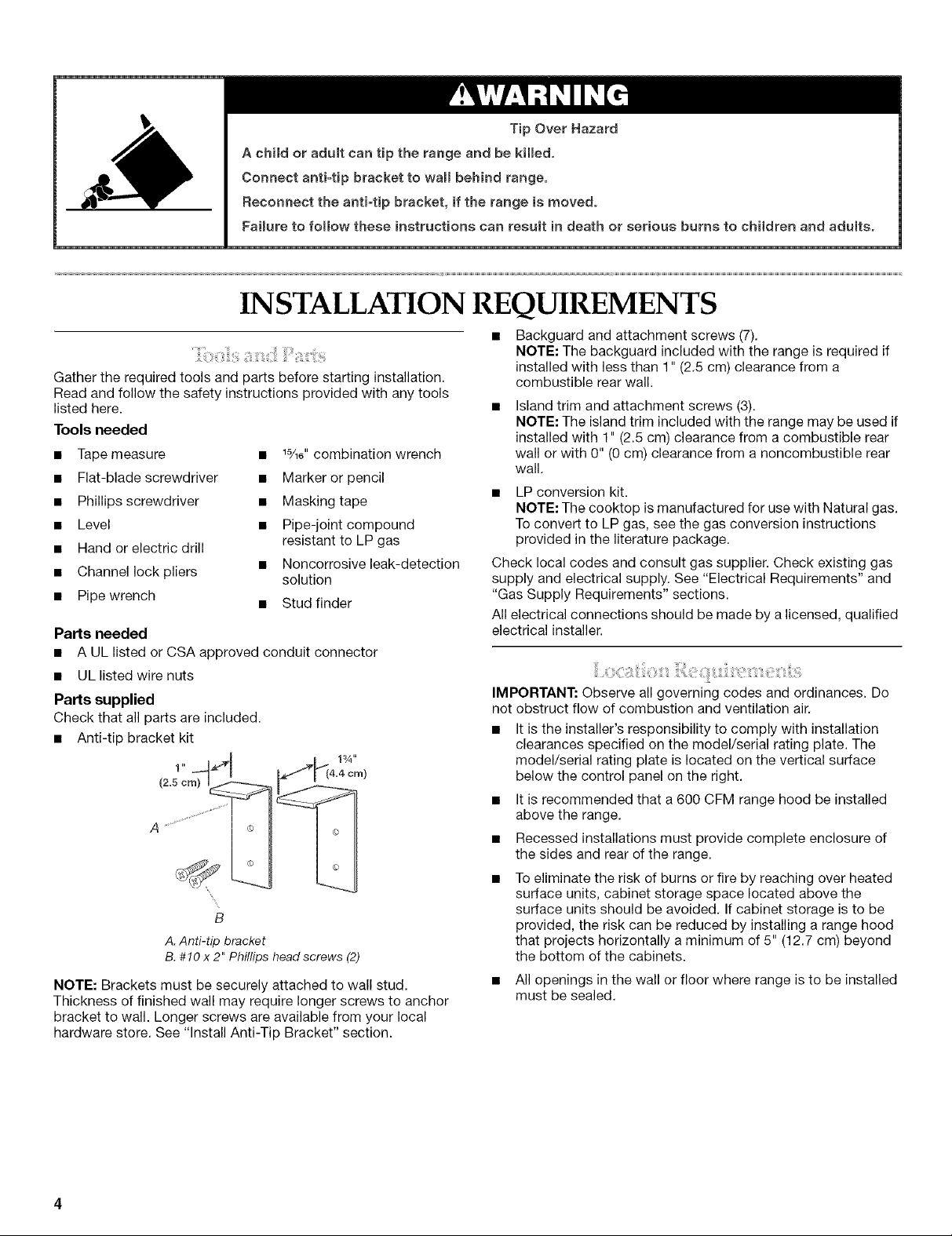
• Anti-tip bracket kit
(2.51"cm)"_ 11_ I_'Jv_4.4 crn)
B
A. Anti-tip bracket
B.#!0 x 2" Phillips headscrews (2)
NOTE: Brackets must be securely attached to wall stud.
Thickness of finished wall may require longer screws to anchor
bracket to wall. Longer screws are available from your local
hardware store. See "Install Anti-Tip Bracket" section.
resistant to LP gas
solution
• Stud finder
TipOverHazard
• Backguard and attachment screws (7).
NOTE: The backguard included with the range is required if
installed with less than 1" (2.5 cm) clearance from a
combustible rear wall.
Island trim and attachment screws (3).
NOTE: The island trim included with the range may be used if
installed with 1" (2.5 cm) clearance from a combustible rear
wall or with 0" (0 cm) clearance from a noncombustible rear
wall.
LP conversion kit.
NOTE: The cooktop is manufactured for use with Natural gas.
To convert to LP gas, see the gas conversion instructions
provided in the literature package.
Check local codes and consult gas supplier. Check existing gas
supply and electrical supply. See "Electrical Requirements" and
"Gas Supply Requirements" sections.
All electrical connections should be made by a licensed, qualified
electrical installer.
IMPORTANT: Observe all governing codes and ordinances. Do
not obstruct flow of combustion and ventilation air.
• It is the installer's responsibility to comply with installation
clearances specified on the model/serial rating plate. The
model/serial rating plate is located on the vertical surface
below the control panel on the right.
• It is recommended that a 600 CFM range hood be installed
above the range.
• Recessed installations must provide complete enclosure of
the sides and rear of the range.
To eliminate the risk of burns or fire by reaching over heated
surface units, cabinet storage space located above the
surface units should be avoided. If cabinet storage is to be
provided, the risk can be reduced by installing a range hood
that projects horizontally a minimum of 5" (12.7 cm) beyond
the bottom of the cabinets.
• All openings in the wall or floor where range is to be installed
must be sealed.
Donotsealtherangetothesidecabinets.
Cabinetopeningdimensionsthatareshownmustbeused.
Givendimensionsareminimumclearances.
Thewallanti-tipbracketmustbeinstalled.Toinstalltheanti-
tipbracketshippedwiththerange,see"InstallAnti-Tip
Bracket"section.
Groundedelectricalsupplyisrequired.See"Electrical
Requirements"section.
Propergassupplyconnectionmustbeavailable.See"Gas
SupplyRequirements"section.
Contactaqualifiedfloorcoveringinstallertocheckthatthe
floorcoveringcanwithstandatleast200°F(93°C).Usean
insulatedpador1A"(0.64cm)plywoodovercarpetandunder
rangeifinstallingrangeovercarpeting.
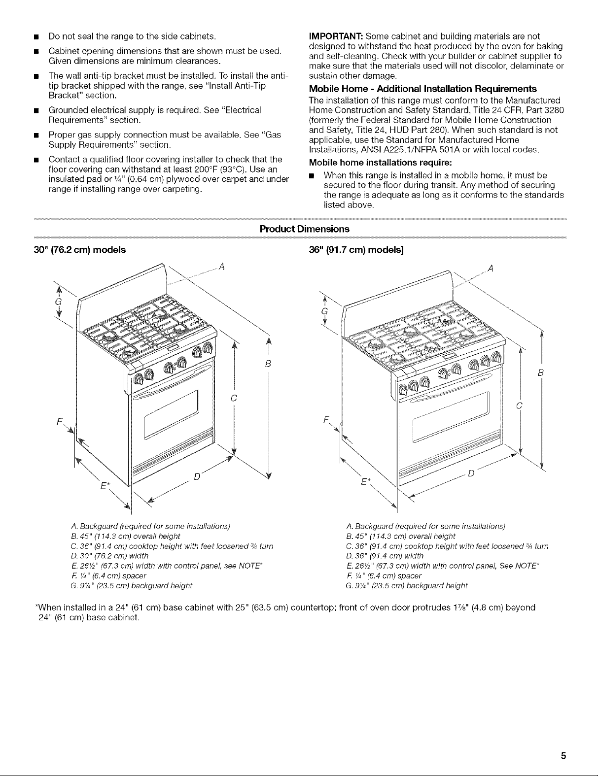
Product Dimensions
30" (76.2 cm) models 36" (91.7 cm) models]
IMPORTANT:Somecabinetandbuildingmaterialsarenot
designedtowithstandtheheatproducedbytheovenforbaking
andself-cleaning.Checkwithyourbuilderorcabinetsupplierto
makesurethatthematerialsusedwillnotdiscolor,delaminateor
sustainotherdamage.
Mobile Home - Additional Installation Requirements
The installation of this range must conform to the Manufactured
Home Construction and Safety Standard, Title 24 CFR, Part 3280
(formerly the Federal Standard for Mobile Home Construction
and Safety, Title 24, HUD Part 280). When such standard is not
applicable, use the Standard for Manufactured Home
Installations, ANSI A225.1/NFPA 501A or with local codes.
Mobile home installations require:
• When this range is installed in a mobile home, it must be
secured to the floor during transit. Any method of securing
the range is adequate as long as it conforms to the standards
listed above.
C
F
E*
\
A. Backguard (required for some installations)
B.45" (114.3 cm) overall height
C. 36" (91.4 cm) cooktop height with feet loosened 3/_turn
D. 30" (76.2 cm) width
EL26_/2"(67.3 cm) width with control panel, see NOTE*
F. _/4"(6.4 cm) spacer
G. 9¼" (23.5 cm) backguard height
*When installed in a 24" (61 cm) base cabinet with 25" (63.5 cm) countertop; front of oven door protrudes 1%" (4.8 cm) beyond
24" (61 cm) base cabinet.
A. Backguard (required for some installations)
B. 45" (114.3 cm) overall height
C. 36" (91.4 cm) cooktep height with feet loosened _/_turn
D. 36" (91.4 cm) width
E. 26_" (67.3 cm) width with control panel, See NOTE*
F. ¼" (6.4 cm) spacer
G. 9_/4"(23.5 cm) backguard height
B
 Loading...