

Page 1

KD-27A SERIES
DISHWASHERS
FORM 4171083 (153138) 3-86
INSTALLATION
INSTRUCTIONS
Page 2

THIS PAGE
INTENTIONALLY LEFT
BLANK
Page 3
BEFORE STARTING:
Please read these installation instructions COMPLETELY AND CAREFULLY. They will save you time, work, and
help to ensure optimum dishwasher performance.
For Replacement Installation - Review these complete instructions to be sure that previous connections are
compatible.
For New Installations - Plumbing and electrical connections must be provided before the dishwasher is moved
into place.
These instructions are intended for use by qualified workers who will observe all local codes and ordinances for
plumbing connections as well as local codes and/or the national Electrical Code for electrical connections.
YOU WILL NEED THESE TOOLS:
Phillips Screwdriver
Flat Blade Screwdriver
Adjustable Wrenches (2) (if copper fittings are used)
Pipe Wrenches (2) (if galvanized or iron fittings are used)
Nut Driver or Socket Set
Wire Cutters
Tape Measure
Spirit/Bubble Level
Electric Drill
1” Drill Bit or Hole Saw
Square
. . .
112”
3/g” Pipe (of sufficient length for your installation), Shut-off Valve, and Fittings (for galvanized water supply line)
3%~” NPT Street Elbow (you will need 2 for galvanized water supply line) or 90° Compression Elbow (3%” NPT
g/I6” ID Heat and Detergent Resistant Rubber Hose and Clamps or5/g” OD Copper Tubing and Fittings (of sufficient
10” Length of s/a” OD Soft Copper Tubing, Formed Into a Semicircle (if high loop drain is required - see page 7)
115 Volt, 15 Amp, 2 Wire, Properly Grounded, Branch Circuit
AND THESE MATERIALS:
OD Copper Tubing (of sufficient length for your installation), Shut-off Valve, and Fittings (for copper water
supply line)
one end, for copper water supply line) See Fig. 13 page. 10.
length to accommodate your drain line)
-3-
Page 4
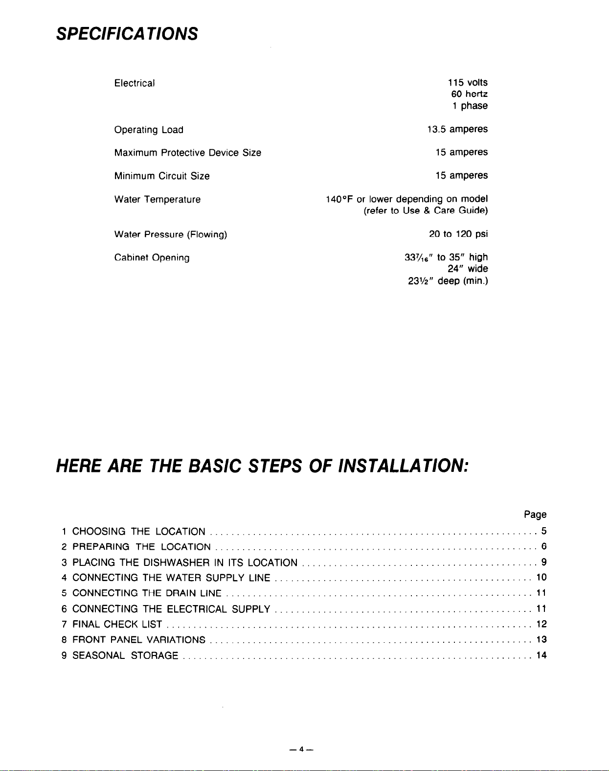
SPECIFICA T/O/W
Electrical
Operating Load
Maximum Protective Device Size
Minimum Circuit Size
Water Temperature
Water Pressure (Flowing)
Cabinet Opening
115 volts
60 hertz
1
phase
13.5 amperes
15 amperes
15 amperes
140°F or lower depending on model
(refer to Use & Care Guide)
20 to 120 psi
337/1grr to 35” high
24” wide
23’/2” deep (min.)
HERE ARE THE BASIC STEPS OF INSTALLATION:
1 CHOOSING THE LOCATION
2 PREPARING THE LOCATION
3 PLACING THE DISHWASHER IN ITS LOCATION
4 CONNECTING THE WATER SUPPLY LINE
5 CONNECTING THE DRAIN LINE
6 CONNECTING THE ELECTRICAL SUPPLY
7 FINAL CHECK LIST
8 FRONT PANEL VARIATIONS
9 SEASONAL STORAGE
-4-
.............. 5
..............
..............
............. 10
............. 11
............. 11
............. 12
.............
.............
Page
6
9
13
14
Page 5
1
CHOOSING THE LOCA T/ON
For easy access to plumbing, it is most convenient to have your dishwasher located near the kitchen sink.
Any built-in dishwasher must be fully enclosed on the top, both sides, and the back. Therefore, the cabinet space
below your kitchen counter is probably the best location. If the dishwasher is being installed at the end of a cabinet
or free standing then side panels and a wood top can be purchased from your KitchenAid dealer to enclose the
dishwasher.
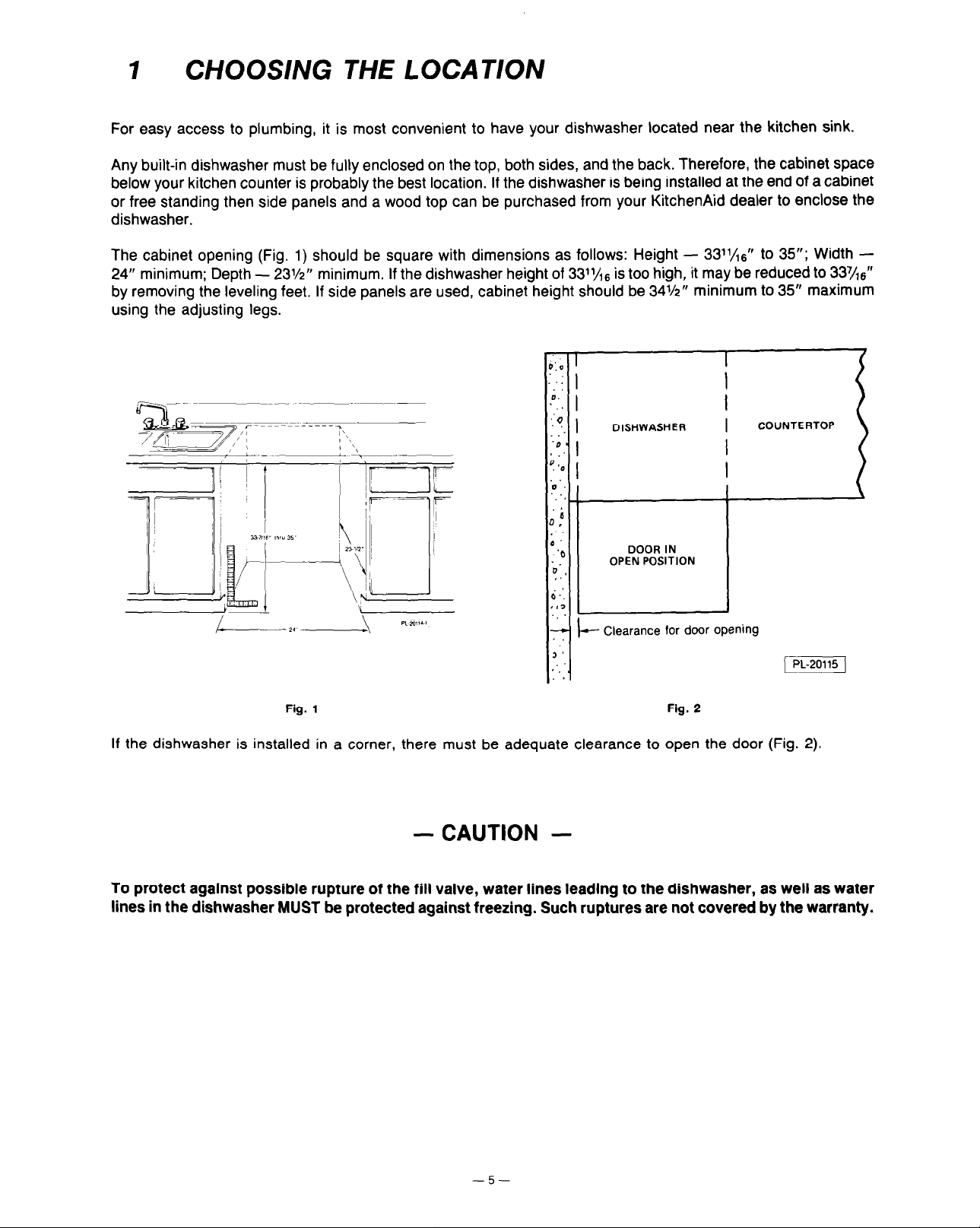
The cabinet opening (Fig. 1) should be square with dimensions as follows: Height - 3311/16” to 35”; Width 24” minimum; Depth -
23X” minimum. If the dishwasher height of 3311/r6 is too high, it may be reduced to 337/16”
by removing the leveling feet. If side panels are used, cabinet height should be 34%” minimum to 35” maximum
using the adjusting legs.
7
I-
‘:O
D.
‘0
.D
! ‘a
0‘
1 ,
,
-‘C
il
.
6 _I
IL
‘_
4
1
6
DISHWASHER
DOOR IN
OPEN POSITION
- Clearance for door
I
opening
COUNTERTOP
Fig. 1
Fig. 2
If the dishwasher is installed in a corner, there must be adequate clearance to open the door (Fig. 2).
- CAUTION -
To protect against possible rupture of the fill valve, water lines leading to the dishwasher, as well as water
lines in the dishwasher MUST be protected against freezing. Such ruptures are not covered by the warranty.
-5-
Page 6

2 PREPARING THE LOCATION
Access holes in the cabinets, floor, or rear wall for the hot water supply line, drain line, and electrical supply must
be located within the shaded area in Fig. 3 in order to avoid interference with the dishwasher frame or other
components.
HOT WATER SUPPLY LINE
WARNING:
PLUMBING CODES.
Water supply should be 140°F or lower depending on model (refer to Use and Care Guide).
The hot water supply line should be l/2” OD copper tubing or 3/g” galvanized pipe. The dishwasher fill valve has
a 3/B” NPT female connection.
After determining where the water supply line will enter the dishwasher opening, drill a 1” access hole and run
the line to the approximate fill valve location as shown in Fig. 4.
PLUMBING CONNECTIONS MUST COMPLY WITH APPLICABLE SANITARY, SAFETY, AND
-6-
Page 7

For service convenience, a shut-off valve (not supplied) should be installed in the supply line in a readily accessible
location (such as beneath the sink) and a union (not supplied) should be installed in the supply line near the
dishwasher fill valve.
- CAUTION -
To prevent heat damage to the fill valve, ALL solder connections must be made BEFORE the water line is
connected to the dishwasher.
DRAIN LINE
The drain line should be 9/16” ID (minimum) flexible hose or 5/l’ OD copper tubing. Flexible hose must be resistant
to heat and detergent and may be obtained from a plumbing, hardware, or automotive supply outlet. DO NOT use
any fittings anywhere in the drain line that are less than l/z”
If drain line is copper, clamp a 12” length of s6” ID flexible hose (heat and detergent resistant) to the end of the
copper tubing. This will facilitate connection of the drain line to dishwasher check valve.
If the drain line is going to be connected to a food waste disposer, BE SURE to remove the knockout or
plug from the fitting on the disposer before connecting drain line. Rubber adapter fitting may be required.
(KitchenAid part number 115729 or available from local hardware or plumbing stores.)
Typical drain connections to sink plumbing are shown
Illal” 01 d,sprer connecllon
ID. The access hole for the drain line should be 1”.
in
Fig. 5 & 6.
Fig. 5
Fig. 6
Typical drain connection to an air gap (if required by local code) are shown in Fig. 6.
If drain is rounted to a connection point less than 20” above the floor, the drain line MUST be made to form
a high loop tube (shown in Fig. 7).
CAUTION: Failure to provide either the proper drain connection height (20” above floor level) or a 20” high
loop will result in improper draining of the machine which may cause damage to the machine.
To form the high loop tube, see inset on Fig. 7. Make sure that no kinks develop in the hose or copper tubing.
Fig. 7
-7-
Page 8

ELECTRICAL SUPPLY
WARNING: ELECTRICAL AND GROUNDING CONNECTIONS MUST COMPLY WITH THE NATIONAL
ELECTRICAL CODE AND/OR OTHER LOCAL CODES.
WARNING: DISCONNECT ELECTRICAL POWER SUPPLY.
The electrical supply must be a 115 volt, 15 amp, properly grounded, positioned as shown in Fig. 8, and should
be installed by a qualified electrician. No other appliances or outlets should be on this circuit.
4
CHANNEL
2
TAB
Fig. 9
ADJUbABLE
\
KICKBOARD
Fig. 9
Page 9

3 PLACING THE DISHWASHER IN ITS LOCATION
The adjustable kickboard and lower panel (Fig. 9) must be removed for access to dishwasher connections. Remove
the kickboard (5) by removing the two screws (one with lock washer) that secure it. Remove two screws (1) and
pull out the bottom of lower panel to unhook tabs (2) from frame. Remove the lower panel by pulling it downward
to slide panel flanges (3) from behind the support channel (4).
Set the dishwasher in front of the prepared cabinet opening and evenly.adjust the four leveling feet to the desired
height.
Slide the dishwasher into the cabinet opening, being careful to avoid damage to the floor or interference with water,
drain, and electrical lines. DO NOT remove the rear cross channel.
Back of dishwasher
Rear cross channel
in alternate position
Step 3 - Loosen
this screw
( Step 4 - Line up the lower cross
1
I/
channel hole with the
upper hole in frame.
Fasten securely Tighten the
screw at other end
Step 2 - Remove
Unlatch and open the door and remove the foam shipping cushions from upper corners of the door. Check to assure
that cabinet clearance is equal on both sides of the dishwasher and that cabinet interference does not distort
dishwasher tank.
With the door still open, place a spirit/bubble level against the front tank flange (Fig. 11) and level the dishwasher
front-to-back and side-to-side by adjusting the leveling legs (Fig. 12) in or out as necessary.
this screw
Fig. 10
b
Rear cross channel
in original position
STEP 1 - Remove
these screws
,
Fig. 11
If the dishwasher is not properly leveled or if it is distorted by cabinet interference, the door may not seal properly
and may leak. If necessary, the leveling leg may be further adjusted to correct any distortion and align tank for
equal clearance on both sides (Fig. 12).
-9-
‘PL-loiio-1’
Page 10

To maintain dishwasher position and alignment, locate the adjustable brackets at the upper tank corners as shown
in Fig. 13 and secure them to the counter top with self drilling flat head wood screws (supplied).
sure screw heads will not interfere with the top of the door.
countertop, the dishwasher may be anchored to the floor with a VI”
If these brackets are not compatible with your
lag bolt (not supplied) through the hole in
CAUTION
:Make
each side of the dishwasher frame as shown in Fig. 12.
Fig. 13
4
CONNECTING THE WATER SUPPLY LINE
The water supply line should be flushed to clear any foreign material BEFORE connecting to dishwasher.
Make sure there are no sharp bends or kinks which might restrict water flow.
To facilitate connection of the water line from the rear of the dishwasher, it is recommended that a j/a” NPT street
elbow be connected to the fill valve and a 90° compression elbow (3/8” NPT one end) be connected to the street
elbow. The supply line can then be connected to the compression elbow (see Fig. 14).
NOTE:
If galvanized pipe
is used, substitute a second 3/8” street elbow for the compression elbow.
Turn on water supply and check for leaks.
Compression Sleeve
l/Z” 00 copper
wIl,er llfw
(3/S” NPT one end)
Fig. 14
-lO-
Page 11

5 CONNECTING THE DRAIN LINE
Remove the red plug from the dishwasher check valve and use a hose clamp (not supplied) to connect the prepared
drain line directly to the dishwasher check valve (Fig. 15).
Make sure there are no sharp bends or kinks anywhere in the drain line which might restrict water flow.
Fig. 15
Fig. 16
6 CONNECTING THE ELECTRlCAL SUPPLY
WARNING: BE SURE ELECTRICAL POWER IS TURNED OFF AT CIRCUIT BREAKER OR FUSE BOX.
The dishwasher must be properly grounded before operating by connecting to a suitable ground in compliance
with the National Electrical Code and/or local electrical codes.
A - Remove junction box from dishwasher, B -
white lead to white lead and back lead to black lead with wire nuts, and secure ground wire under the green ground
screw (Fig. 16). D - Reinstall junction box.
Install a UL Lised connector or strain relief bushing. C - Connect
When house wiring is aluminum, use UL listed aluminum to copper connectors.
WARNING: MAKE SURE THAT WATER SUPPLY LINE, DRAIN LINE, AND WIRING DO NOT TOUCH ANY
EXPOSED TERMINALS OF DISHWASHER WIRING.
- 11 -
Page 12

7 FlNAL CHECK LIST
Open the dishwasher door and remove all cardboard, and literature. DO NOT remove the white plastic plug buttons
(Fig. 17) from sides of door or the white plastic bumpers on front corners of the lower rack. DO NCrr remove the
two spring retainers (Fig. 18) attached to the tank water heater if dishwasher is so equipped.
Fig. 17 Fig. 18
Turn on the electrical power supply.
Test dishwasher operation:
1.
Push buffon models - Close and latch the door. Press Cancel Cycle button, timer will automatically advance
to off. Lift the door handle and allow several seconds for the timer to reset. Latch the door handle, press Normal
Wash button, and allow the dishwasher to run through a complete cycle,
2. Cycle Selection Dial Models - Close and latch the door. Turn the dial clockwise until it clicks into the Normal
Wash position. Press Start or Normal Wash button and allow the dishwasher to run through a complete cycle.
3. Solid State Models - Close and latch door. PF appears in display. Press Cancel
Turn off the electrical power and check for leaks
under the dishwasher. Make sure that no kinks
have developed in the fill or drain lines.
The lower panel and adjustable kickboard (Fig. 19)
must be replaced. Line up panel flanges (3) to fit
under lip of channel (4). Slide panel up until it
stops and then push up tabs (2) to hook over the
frame. Secure the lower panel with two screws (1).
Replace the kickboard using two screws (one with
lock washer). Check to assure that the opening
at the bottom of the kickboard is not obstructed
(e.g., by carpet, molding, etc.). This area must be
open to provide air circulation to cool the motor.
This completes dishwasher installation. For more
information about the dishwasher, please refer
to your Use and Care Guide.
- 12 -
Page 13

8 FRONT PANEL VARIATIONS
Vari-Front Panel Pack -
All KitchenAid dishwashers are equipped with reversible front panels. If you wish to change
the color of your dishwasher panels, consult your Use and Care Guide for instructions on how to reverse these panels.
Custom Panels - If custom wood or decorator front panels are to be used, they should be I/,” thick. Length and
width dimensions should be the same as the Vari-Front panel inserts. If wood panels are less than %I” thick, they
must be shimmed up to the required I/,” with appropriately sized back up board (corrugated cardboard, masonite,
etc.). If wood panels are thicker than I/,“,
the edges will have to be trimmed down on all four sides as shown in
Fig. 20. CAUTION: The finish applied to custom wood panels should be applied to the front, back, and all
edges, and must be waterproof since a certain amount of moist air is discharged from the machine.
Fig. 20
Fig. 21
The use of custom panels may necessitate adjustment of the door tension. The door should be counterbalanced
(i.e. doesn’t fall open when unlatched or pull itself closed from the open position).
If the door pulls itself closed from the open (horizontal) position, close the door and adjust the door springs
by moving the adjustable door spring brackets (Fig. 21) upward to alternate holes. Move brackets downward
if the door falls open too quickly.
If the custom panels are too heavy and the door still falls open when unlatched, heavy duty door springs should
be ordered from your KitchenAid dealer.
- 13 -
Page 14

9 SEASONAL STORAGE
- CAUTION -
To protect against possible rupture of the fill valve, water lines leading to the diwasher, as well as water
lines in the dishwasher MUST BE PROTECTED AGAINST FREEZING. Such ruptures are not covered by the
warranty.
For installation where the dishwasher is to be left unused and subjected to freezing temperatures, it must
be prepared as outlined in your Use and Care Guide.
-
14
-
Page 15

THIS PAGE
INTENTIONALLY LEFT
BLANK
Page 16

KitchenAid
Major Appliances
FORM 4171083 (153138) 3-86
PRINTED IN U.S.A.
 Loading...