

A
B
C
D
E
F
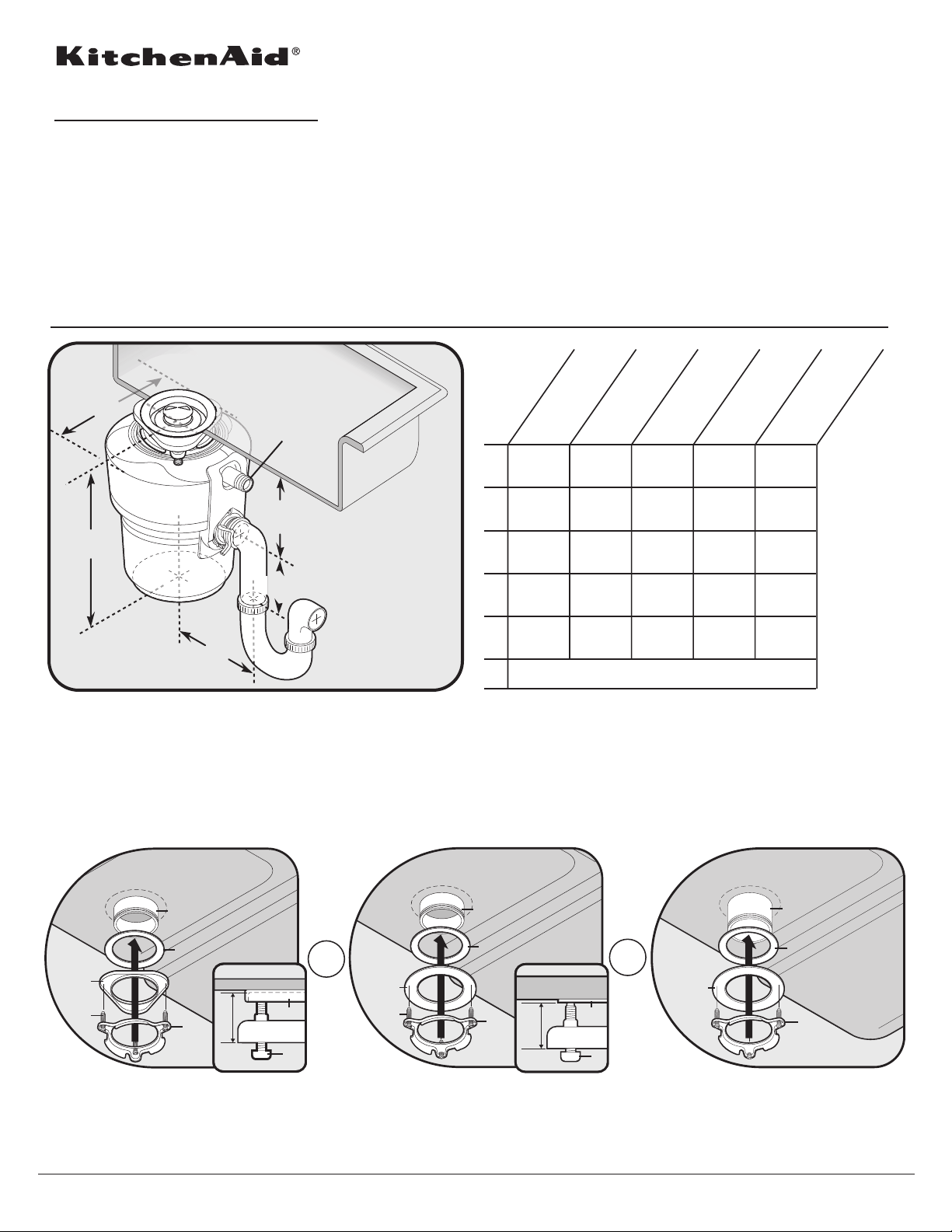
Food Waste Disposer
PRODUCT MODEL NUMBER
KCDB250G KCDS100T
KCDI075V KBDS100T
KCDS075T
Electrical: This disposer is intended to be direct-wired to the electrical supply. If junction box is used, connect the junction box to the switch
on a separate 15- or 20-amp 115 Volt circuit with the appropriate cable. (Use 14 gauge wire with 15-amp circuit, and 12 gauge wire with 20-amp
circuit.) This disposer requires a switch marked "Off" position (wired to disconnect all ungrounded supply conductors) installed within sight of the
disposer sink opening. (1 hp minimum rating.)
OVERALL DIMENSIONS
Installations on thicker sinks (such as solid surface, porcelain, or cast iron) may require the use of alternate parts.
FIGURE A: Thin Sink
All Models
(< 3/8")
KCDB250G
6 5/16"
A
(16.0 cm)
3
11
B
C
D
E
/8"
(28.9 cm)
3
5
/4"
(14.6 cm)
4"
(10.2 cm)
6"
(15.2 cm)
F
See instructions below for installation with various thicknessess:
KCDI075V
1
8
/2"
(21.6 cm)
3
12
/4"
(30.5 cm)
3
5
/4"
(14.6 cm)
4"
(10.2 cm)
11
6
/16"
(17 cm)
Dishwasher Drain Connection
9"
(22.9 cm)
3
12
/4"
(30.5 cm)
3
5
/4"
(14.6 cm)
4"
(10.2 cm)
11
6
/16"
(17 cm)
FIGURE B: Thick Sink
All Models
(> 3/8")
KCDS075T
KCDS100T
9"
(22.9 cm)
3
12
/4"
(30.5 cm)
3
5
/4"
(14.6 cm)
4"
(10.2 cm)
11
6
/16"
(17 cm)
KBDS100T
9"
(22.9 cm)
3
12
/4"
(30.5 cm)
3
5
/4"
(14.6 cm)
4"
(10.2 cm)
11
6
/16"
(17 cm)
FIGURE C: Extra Thick Sink
For Model KBDS100T Only
(> 3/4")
C
E1
G1
For thin sinks insert ber gasket (D), backup
ange (E1) and mounting ring (F). Hold in place
while inserting the snap ring.
C = Standard Sink Flange
G1 = 1 1/2" screws
G2 = 1 1/8" screws
Because Whirlpool Corporation policy includes a continuous commitment to improve
our products, we reserve the right to change materials and specifications without notice.
D
F
1-1/8”
or
E1
F
G1
C
D
E2
G2
For thick sinks insert ber gasket (D), backup
ange (E2) and mounting ring (F). Hold in place
while inserting the snap ring.
F
7/8”
Dimensions are for planning purposes only. For complete details, see Installation
Instructions packed with product. Specifications subject to change without notice.
E2
F
G2
or
N
D
E2
F
For extra thick sinks use extended sink ange (N),
to order in US call 1-800-422-1230, in Canada
call 1-800-6777. Insert ber gasket (D), backup
ange (E2) and mounting ring (F). Hold in place
while inserting the snap ring.
W10118055 Rev. A
02-20-09
 Loading...