

KitchenAid KBPU182VSS00 Owner’s Manual
I_itchen_kid ®
OUTDOOR BUILT-IN POWER TMBURNER
For questions about features, operation/performance, parts, accessories or service, call: 1-800-422-1230
In Canada, call for assistance, installation and service, call: 1-800-807-6777
or visit our website at www.kitchenaid.com
or visit our website at www.KitchenAid.ca
BRULEUR HAUTE PUISSANCE ENCASTRE
P
POWER TMPOUR USAGE EXTERIEUR
Au Canada, pour assistance, installation ou service composez le 1-800-807-6777 ou visitez notre site Web a...
www.KitchenAid.ca
Table of Contents/Table des matieres ............................................................................. 4
iMPORTANT:
Save for local electrical inspector's use.
Installer: Leave installation instructions with the homeowner.
Homeowner: Keep installation instructions for future reference.
iMPORTANT :
_, conserver pour consultation par I'inspecteur local des installations _lectriques.
InstaHateur : Remettre les instructions d'installation au propri_taire.
Propri6taire : Conserver les instructions d'installation pour r_f_rence ult_rieure.
Model/Modele KBPU182VSS
W10243318A
OUTDOOR BUILT-IN POWER TMBURNER SAFETY
Your safety and the safety of others are very important.
We have provided many important safety messages in this manual and on your appliance. Always read and obey all safety
messages.
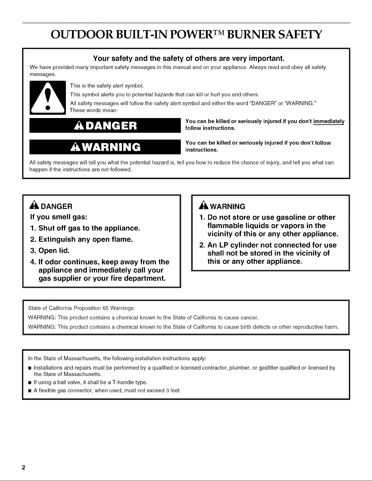
This is the safety alert symbol.
This symbol alerts you to potential hazards that can kill or hurt you and others.
All safety messages will follow the safety alert symbol and either the word "DANGER" or "WARNING."
These words mean:
You can be killed or seriously injured if you don't immediately
follow instructions.
You can be killed or seriously injured if you don't follow
instructions.
All safety messages will tell you what the potential hazard is, tell you how to reduce the chance of injury, and tell you what can
happen if the instructions are not followed.
_, DANGER
If you smell gas:
1. Shut off gas to the appliance.
,_ WARNING
1. Do not store or use gasoline or other
flammable liquids or vapors in the
vicinity of this or any other appliance.
2. Extinguish any open flame.
2. An LP cylinder not connected for use
3. Open lid.
4. If odor continues, keep away from the
shall not be stored in the vicinity of
this or any other appliance.
appliance and immediately call your
gas supplier or your fire department.
State of California Proposition 65 Warnings:
WARNING: This product contains a chemical known to the State of California to cause cancer.
WARNING: This product contains a chemical known to the State of California to cause birth defects or other reproductive harm.
In the State of Massachusetts, the following installation instructions apply:
m Installations and repairs must be performed by a qualified or licensed contractor, plumber, or gasfitter qualified or licensed by
the State of Massachusetts.
m If using a ball valve, it shall be a T-handle type.
m A flexible gas connector, when used, must not exceed 3 feet.
2
IMPORTANT: This Power TM burner is manufactured for outdoor use only. For Power TMburners that are to be used at elevations
above 2000 ft (609.6 m) orifice conversion is required. See "Gas Supply Requirements" section. It is the responsibility of the installer to
comply with the minimum installation clearances specified on the model/serial rating plate. The model/serial rating plate can be found
on the right-hand side panel.
Copies of the standards listed may be obtained from:
National Fire Protection Association CSA International
One Batterymarch Park 8501 East Pleasant Valley Rd.
Quincy, Massachusetts 02269 Cleveland, Ohio 44131-5575
iMPORTANT SAFETY iNSTRUCTiONS
WARNING: To reduce the risk of fire, electrical shock,
injury to persons, or damage when using the outdoor cooking
gas appliance, follow basic precautions, including the
following:
m Do not install portable or built-in outdoor cooking gas
appliances in or on a recreational vehicle, portable trailer,
boat or in any other moving installation.
m Always maintain minimum clearances from combustible
construction, see "Location Requirements" section.
m The outdoor cooking gas appliance shall not be located
under overhead unprotected combustible construction.
m This outdoor cooking gas appliance shall be used only
outdoors and shall not be used in a building, garage, or any
other enclosed area.
m Keep any electrical supply cord and fuel supply hose away
from any heated surfaces.
m Keep outdoor cooking gas appliance area clear and free
from combustible materials, gasoline and other flammable
vapors and liquids.
[] Do not obstruct the flow of combustion and ventilation air.
Keep the ventilation openings of the cylinder enclosure free
and clear from debris.
[] Inspect the gas cylinder supply hose before each use of the
outdoor cooking gas appliance. If the hose shows
excessive abrasion or wear, or is cut, it MUST be replaced
before using the outdoor cooking gas appliance. Contact
your dealer and use only replacement hoses specified for
use with the outdoor cooking gas appliance.
[] Visually check the burner flames. They should be blue.
Slight yellow tipping is normal for LP gas.
[] Check and clean burner/venturi tube for insects and insect
nest. A clogged tube can lead to fire under the outdoor
cooking gas appliance.
[] The LP gas supply cylinder to be used must be:
- constructed and marked in accordance with the
Specification for LP Gas Cylinders of the U.S. Department
of Transportation (DOT) or the National Standard of
Canada, CAN/CSA-B339, Cylinders, Spheres, and Tubes
for Transportation of Dangerous Goods; and Commission.
- provided with a listed overfilling prevention device.
- provided with a cylinder connection device compatible
with the connection for outdoor cooking gas appliances.
[] Always check connections for leaks each time you connect
and disconnect the LP gas supply cylinder. See
"Installation Instructions" section.
[] When the outdoor cooking gas appliance is not in use, the
gas must be turned off at the supply cylinder.
[] Storage of an outdoor cooking gas appliance indoors is
permissible only if the cylinder is disconnected and
removed from the outdoor cooking gas appliance.
[] Cylinders must be stored outdoors and out of the reach of
children and must not be stored in a building, garage, or
any other enclosed area.
[] The pressure regulator and hose assembly supplied with
the outdoor cooking gas appliance must be used. A
replacement pressure regulator and hose assembly
specific to your model is available from your outdoor
cooking gas appliance dealer.
[] Gas cylinder must include a collar to protect the cylinder
valve.
[] For appliances designed to use a CGA791 Connection:
Place a dust cap on cylinder valve outlet whenever the
cylinder is not in use. Only install the type of dust cap on
the cylinder valve outlet that is provided with the cylinder
valve. Other types of caps or plugs may result in leakage
of propane.
If the following information is not followed exactly, a fire
causing death or serious injury may occur.
[] Do not store a spare LP gas cylinder under or near this
outdoor cooking gas appliance.
[] Never fill the cylinder beyond 80 percent full.
SAVE THESE
iNSTRUCTiONS
TABLEOF CONTENTS
TABLEDES MATIERES
OUTDOOR BUILT-IN POWER TM BURNER SAFETY ................... 2
INSTALLATION REQUIREMENTS ................................................ 5
Tools and Parts ............................................................................ 5
Location Requirements ................................................................ 5
Product Dimensions .................................................................... 5
Cabinet Dimensions ..................................................................... 6
Electrical Requirements ............................................................... 9
Gas Supply Requirements ........................................................... 9
Gas Connection Requirements .................................................. 10
INSTALLATION INSTRUCTIONS ................................................ 11
Built-in Outdoor Power TM Burner Installation ............................ 11
Install Tank Tray for 20 Ib LP Gas Fuel Tank ............................. 11
GAS CONVERSIONS .................................................................... 15
Tools and Parts for Gas Conversion .......................................... 15
Conversion to a Local LP Gas Supply ....................................... 15
Conversion from LP Gas to Natural Gas ................................... 16
Check and Adjust the Burners ................................................... 18
USING YOUR OUTDOOR POWER TM BURNER ......................... 19
PowerTM Burner Use .................................................................. 19
LightingYour PowerTM Burner ................................................... 20
OUTDOOR POWER TM BURNER CARE ...................................... 21
General Cleaning ........................................................................ 21
TROUBLESHOOTING .................................................................. 22
ASSISTANCE OR SERVICE ......................................................... 22
In the U.S.A................................................................................ 22
Accessories ................................................................................ 22
In Canada ................................................................................... 22
WAR RANTY .................................................................................. 23
SI_CURITI_ DU BRULEUR HAUTE PUISSANCE ENCASTRI_
POUR USAGE EXTI_RIEUR POWER TM ....................................... 25
EXIGENCES D'INSTALLATION ................................................... 27
Outillage et pieces ...................................................................... 27
Exigences d'emplacement ......................................................... 27
Dimensions du produit ............................................................... 27
Dimensions du placard .............................................................. 27
Specifications electriques .......................................................... 30
Specifications de I'alimentation en gaz ..................................... 31
Exigences concernant le raccordement au gaz ........................ 32
INSTRUCTIONS D'INSTALLATION ............................................. 34
Installation du brQleur haute puissance d'exterieur
encastre Power TM ....................................................................... 34
Installation du chariot de bouteille de gaz propane
de 20 Ib....................................................................................... 34
CONVERSIONS DE GAZ .............................................................. 38
Outillage et pieces ...................................................................... 38
Conversion au gaz propane local .............................................. 38
Conversion du gaz propane au gaz naturel ............................... 39
Contr61e et reglage des brQleurs................................................ 41
UTILISATION DU BRULEUR HAUTE PUISSANCE POWER TM
D'EXTI_RIEUR ............................................................................... 42
Utilisation du brQleur haute puissance Power TM ........................ 42
Allumage du brQleur haute puissance Power TM ........................ 43
ENTRETIEN DU BRULEUR HAUTE PUISSANCE POWER TM
D'EXTI_RIEUR ............................................................................. 44
Nettoyage general ...................................................................... 44
DI_PANNAGE ................................................................................. 45
ASSISTANCE OU SERVICE ......................................................... 46
Accessoires ................................................................................ 46
GARANTIE .................................................................................... 47
INSTALLATION REQUIREMENTS
_?' i_: _ _._1:_
Gather the required tools and parts before starting installation.
Read and follow the instructions provided with any tools listed
here.
Tools Needed
• Tape measure • Wrench or pliers
• Small, flat-blade screwdriver • Pipe wrench
• Flat-blade screwdriver • Scissors or cutting pliers
• #2 and #3 Phillips screwdriver (to remove tiedowns)
• Level • Noncorrosive leak-
Parts Supplied
Gas pressure regulator/hose assembly set for 11" WCP LP
gas (attached to manifold)
• 1 single-prong plug/2,085 mAmp transformer assembly
• Convertible regulator set for 4" WCP Natural gas
• Orifices for Natural gas conversion
• LP gas fuel tank tray
Parts Needed
• 20 Ib LP gas fuel tank - approximately 18" (45.7 cm) height
and 12" (30.5 cm) diameter
[,,:}ca ::(_s Reqs,:: te_sle its
Select a location that provides minimum exposure to wind and
traffic paths. The location should be away from strong draft
areas.
Do not obstruct flow of combustion and ventilation air.
Clearance to combustible construction for built-in outdoor
Power TM burners:
• A minimum of 24" (58 cm) must be maintained between the
sides and back and any combustible construction.
• A zero clearance may be maintained below the cooking
surface and any combustible construction.
Ignition
detection solution
t A q
t
T-
B
® ©
L
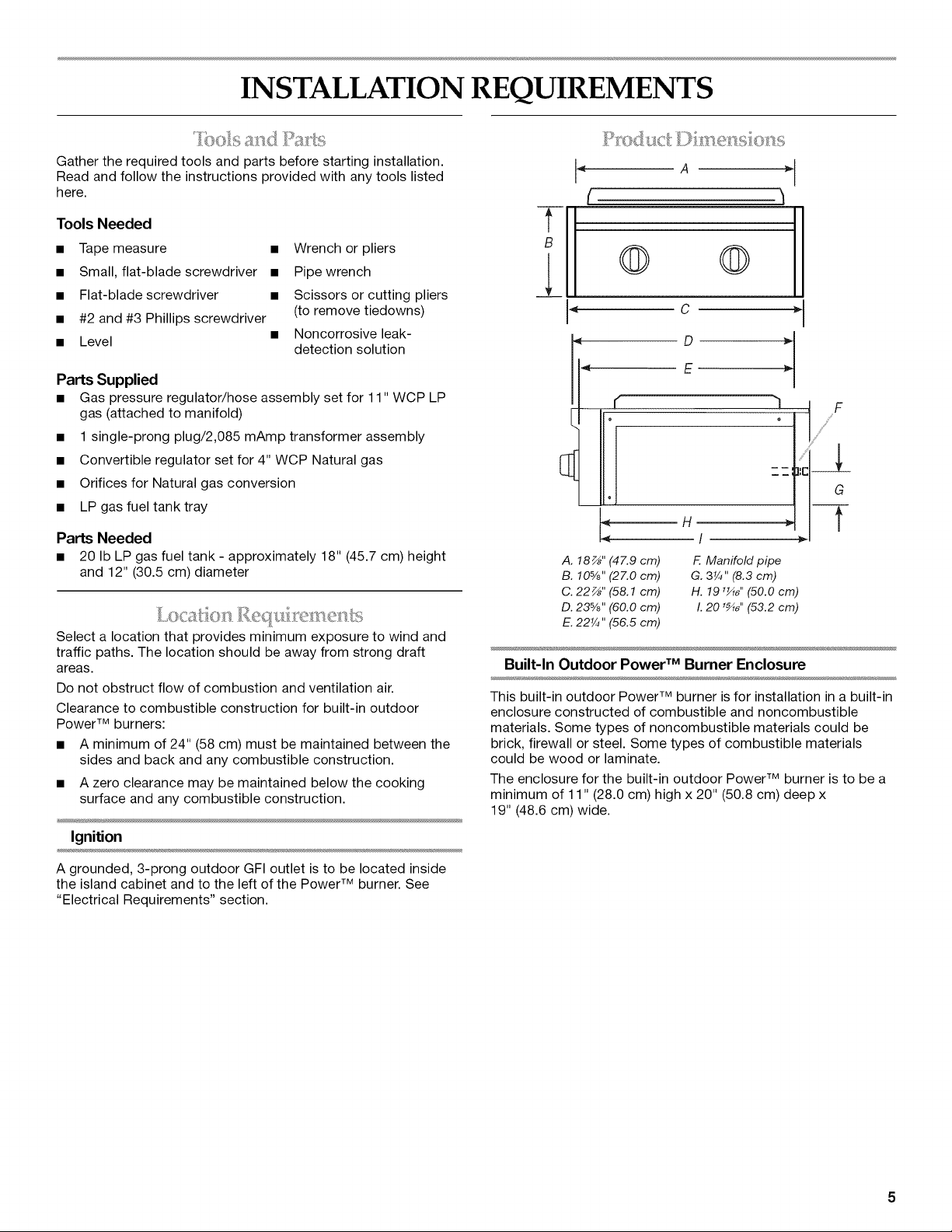
A. 18_" (47.9 cm)
B. 10%" (27.0 cm)
C. 22 z_,,(58.1 cm)
D. 23%" (60.0 cm)
E. 22¼" (56.5 cm)
Built-In Outdoor Power TM Burner Enclosure
This built-in outdoor Power TM burner is for installation in a built-in
enclosure constructed of combustible and noncombustible
materials. Some types of noncombustible materials could be
brick, firewall or steel. Some types of combustible materials
could be wood or laminate.
The enclosure for the built-in outdoor Power TM burner is to be a
minimum of 11" (28.0 cm) high x 20" (50.8 cm) deep x
19" (48.6 cm) wide.
F. Manifold pipe
G. 3¼" (8.3 cm)
H. 191_,, (50.0 cm)
I.201_,, (53.2 cm)
A grounded, 3-prong outdoor GFI outlet is to be located inside
the island cabinet and to the left of the Power TM burner. See
"Electrical Requirements" section.
Counterorsupportsurfacesmustbelevel.
TheinstallationofthisPowerTM burner must conform with local
codes or, in the absence of local codes, with either the National
Fuel Gas Code, ANSI Z223.1/NPFA 54, Natural Gas and Propane
Installation Code, CSA B149.1, or Propane Storage and Handling
Code, B149.2.
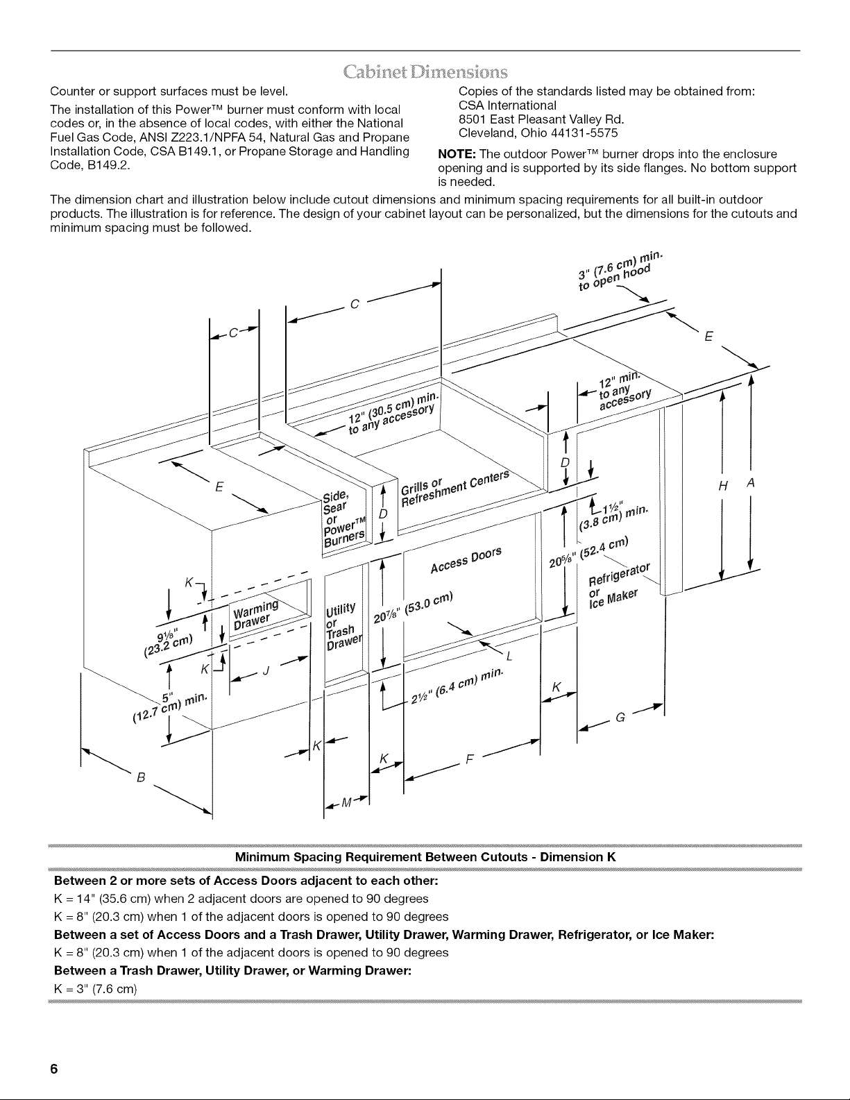
The dimension chart and illustration below include cutout dimensions and minimum spacing requirements for all built-in outdoor
products. The illustration is for reference. The design of your cabinet layout can be personalized, but the dimensions for the cutouts and
minimum spacing must be followed.
C
Copies of the standards listed may be obtained from:
CSA International
8501 East Pleasant Valley Rd.
Cleveland, Ohio 44131-5575
NOTE: The outdoor Power TM burner drops into the enclosure
opening and is supported by its side flanges. No bottom support
is needed.
E
E Gri!ls orrnent C
Refre_"
K
F
Between 2 or more sets of Access Doors adjacent to each other:
K = 14" (35.6 cm) when 2 adjacent doors are opened to 90 degrees
K = 8" (20.3 cm) when 1 of the adjacent doors is opened to 90 degrees
Between a set of Access Doors and a Trash Drawer, Utility Drawer, Warming Drawer, Refrigerator, or Ice Maker:
K = 8" (20.3 cm) when 1 of the adjacent doors is opened to 90 degrees
Between a Trash Drawer, Utility Drawer, or Warming Drawer:
K = 3" (7.6 cm)
H A
6
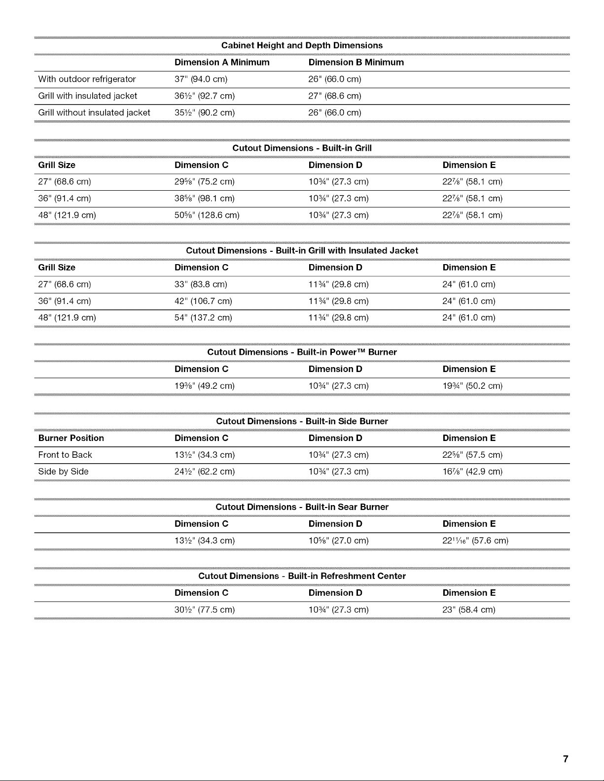
Cabinet Height and Depth Dimensions
Dimension A Minimum
Dimension B Minimum
With outdoor refrigerator
Grill with insulated jacket
Grill without insulated jacket
Grill Size Dimension C Dimension D Dimension E
27" (68.6 cm) 29%" (75.2 cm) 10%" (27.3 cm) 227/8'' (58.1 cm)
36" (91.4 cm) 388/8''(98.1 cm) 10%" (27.3 cm) 227/8'' (58.1 cm)
48" (121.9 cm) 50%" (128.6 cm) 103_'' (27.3 cm) 227/8'' (58.1 cm)
Grill Size Dimension C Dimension D Dimension E
27" (68.6 cm) 33" (83.8 cm) 11%" (29.8 cm) 24" (61.0 cm)
36" (91.4 cm) 42" (106.7 cm) 11%" (29.8 cm) 24" (61.0 cm)
48" (121.9 cm) 54" (137.2 cm) 11%" (29.8 cm) 24" (61.0 cm)
37" (94.0 cm)
361/2''(92.7 cm)
351/2"(90.2 cm)
Cutout Dimensions - Built-in Grill with Insulated Jacket
Cutout Dimensions - Built-in Power TM Burner
Dimension C Dimension D Dimension E
26" (66.0 cm)
27" (68.6 cm)
26" (66.0 cm)
193/8'' (49.2 cm) 103A'' (27.3 cm) 193A'' (50.2 cm)
Cutout Dimensions - Built-in Side Burner
Burner Position Dimension C Dimension D Dimension E
Front to Back 131/2'' (34.3 cm) 10%" (27.3 cm) 228/8'' (57.5 cm)
Side by Side 241/2''(62.2 cm) 103_'' (27.3 cm) 167/8'' (42.9 cm)
Dimension C Dimension D Dimension E
131/2'' (34.3 cm) 10%" (27.0 cm) 221Vie'' (57.6 cm)
Cutout Dimensions - Built-in Refreshment Center
Dimension C Dimension D Dimension E
301/2''(77.5 cm) 10%" (27.3 cm) 23" (58.4 cm)
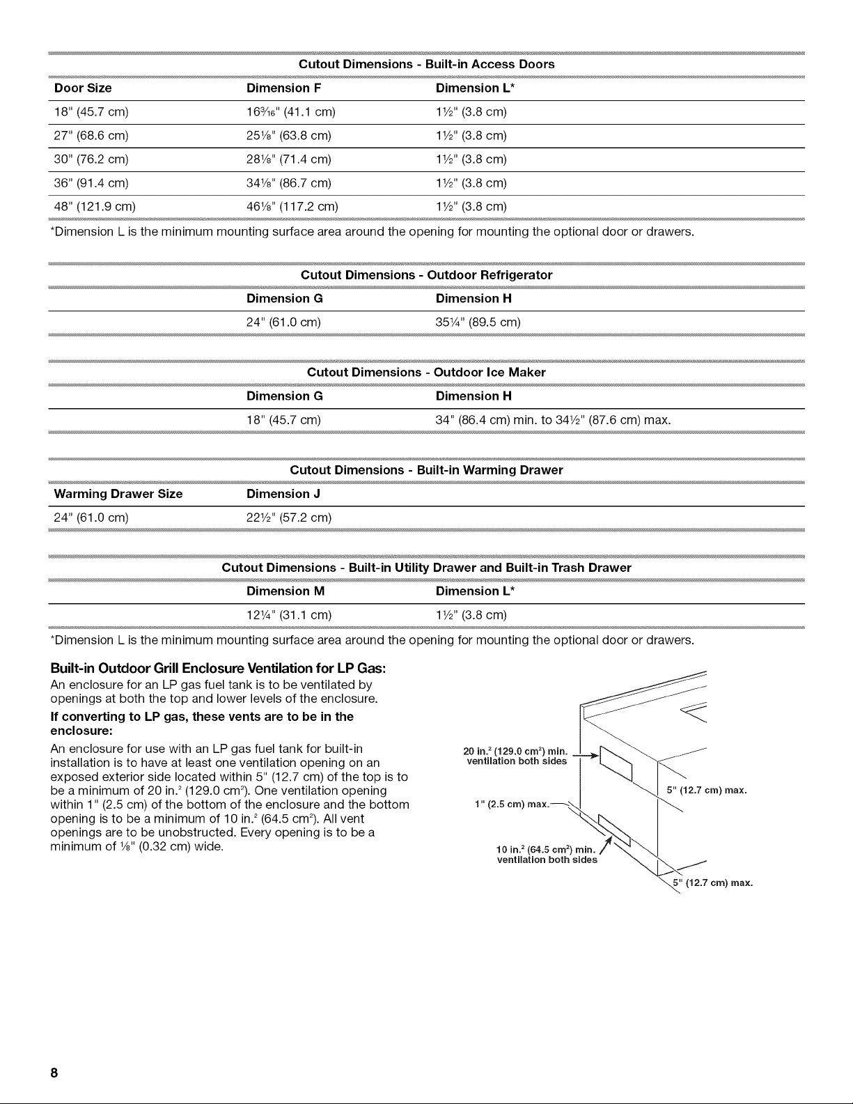
Cutout Dimensions - Built-in Access Doors
Door Size Dimension F Dimension L*
18" (45.7 cm) 163/16"(41.1 cm) 11/2"(3.8 cm)
27" (68.6 cm) 251/8''(63.8 cm) 11/2"(3.8 cm)
30" (76.2 cm) 281/8''(71.4 cm) 11/2"(3.8 cm)
36" (91.4 cm) 341/8''(86.7 cm) 11/2"(3.8 cm)
48" (121.9 cm) 461/8''(117.2 cm) 11/2'' (3.8 cm)
*Dimension L is the minimum mounting surface area around the opening for mounting the optional door or drawers.
Dimension G Dimension H
24" (61.0 cm) 35W' (89.5 cm)
Cutout Dimensions - Outdoor Ice Maker
Dimension G Dimension H
18" (45.7 cm) 34" (86.4 cm) min. to 341/2''(87.6 cm) max.
Cutout Dimensions - Built-in Warming Drawer
Warming Drawer Size Dimension J
24" (61.0 cm) 221/2''(57.2 cm)
Dimension M Dimension L*
12W' (31.1 cm) 11/2'' (3.8 cm)
*Dimension L is the minimum mounting surface area around the opening for mounting the optional door or drawers.
Built-in Outdoor Grill Enclosure Ventilation for LP Gas:
An enclosure for an LP gas fuel tank is to be ventilated by
openings at both the top and lower levels of the enclosure.
If converting to LP gas, these vents are to be in the
enclosure:
An enclosure for use with an LP gas fuel tank for built-in
installation is to have at least one ventilation opening on an
20 in.2(129.0 crn 2) rain.
ventimation both sides
exposed exterior side located within 5" (12.7 cm) of the top is to
be a minimum of 20 in.2(129.0 cm2). One ventilation opening
within 1" (2.5 cm) of the bottom of the enclosure and the bottom
1" (2.5 crn)
5" (12.7 crn) max.
opening is to be a minimum of 10 in.2(64.5 cm_).All vent
openings are to be unobstructed. Every opening is to be a
minimum of 1/8"(0.32 cm) wide.
10 in? (64.5 crn 2)
ventilation both sides
"_' (12.7 crn) max.
8
£:i',l@CI (;.a/_,.@;]!
Electrical Shock Hazard
Plug into a grounded 3 prong outlet.
Do not remove ground prong.
Do not use an adapter.
Do not use an extension cord.
Failure to follow these instructions can result in death,
fire, or electrical shock.
If codes permit and a separate ground wire is used, it is
recommended that a qualified electrician determine that the
ground path is adequate.
Check with a qualified electrician if you are not sure whether the
Power TM burner is properly grounded.
A 120-volt, 60-Hz, AC-only, 15-amp, fused electrical supply is
required.
It is recommended that a separate circuit servicing only this
Power TM burner be provided.
• To avoid electrical shock, do not immerse cord or plugs in
water or other liquid.
• Unplug from the outlet when not in use and before
cleaning. Allow to cool before putting on or taking off
parts.
Do not operate any outdoor cooking gas appliance with a
damaged cord, damaged plug, or after the appliance
malfunctions or has been damaged in any manner.
Contact the manufacturer for repair.
• Do not let the cord hang over the edge of a table or touch
hot surfaces.
• Do not use an outdoor cooking appliance for purposes
other than intended.
• When connecting, first connect plug to the outdoor
cooking gas appliance then plug appliance into the outlet.
• Use only a Ground Fault Interrupter (GFI) protected circuit
with this outdoor cooking gas appliance.
• Do not remove the ground prong or use with an adapter
of 2 prongs.
The model/serial number rating plate is located on the right-hand
side panel. See the following illustration.
A
A. Model/serial number plate
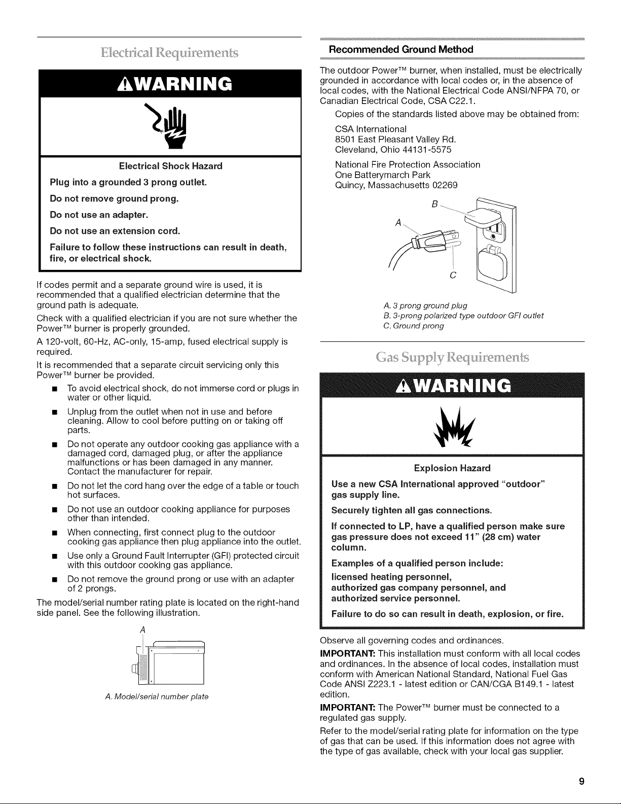
Recommended Ground Method
The outdoor Power TM burner, when installed, must be electrically
grounded in accordance with local codes or, in the absence of
local codes, with the National Electrical Code ANSI/NFPA 70, or
Canadian Electrical Code, CSA C22.1.
Copies of the standards listed above may be obtained from:
CSA International
8501 East Pleasant Valley Rd.
Cleveland, Ohio 44131-5575
National Fire Protection Association
One Batterymarch Park
Quincy, Massachusetts 02269
S ..............................
A ......................
A. 3 prong ground plug
B. 3-prong polarized type outdoor GFI outlet
C. Ground prong
"" _f ; _'_'_ /s /s ,/ _ ..................
Explosion Hazard
Use a new CSA international approved "outdoor"
gas supply line.
Securely tighten all gas connections.
if connected to LP, have a qualified person make sure
gas pressure does not exceed 11" (28 cm) water
column.
Examples of a qualified person include:
licensed heating personnel,
authorized gas company personnel, and
authorized service personnel.
Failure to do so can result in death, explosion, or fire.
Observe all governing codes and ordinances.
IMPORTANT: This installation must conform with all local codes
and ordinances. In the absence of local codes, installation must
conform with American National Standard, National Fuel Gas
Code ANSI Z223.1 - latest edition or CAN/CGA B149.1 - latest
edition.
IMPORTANT: The Power TM burner must be connected to a
regulated gas supply.
Refer to the model/serial rating plate for information on the type
of gas that can be used. If this information does not agree with
the type of gas available, check with your local gas supplier.
GasConversion:
NoattemptshallbemadetoconvertthePowerTM burner from
the gas specified on the model/serial rating plate for use with a
different gas type without consulting the serving gas supplier. The
conversion kits supplied with the Power TM burner must be used.
See "Gas Conversions" section for instructions.
Gas Pressure Regulator
The gas pressure regulator supplied with this Power TM burner
must be used. The inlet (supply) pressure to the regulator should
be as follows for proper operation:
LP Gas:
Set pressure: 11" (27.9 cm) WCP
Inlet (supply) pressure: 11" to 14" (27.9 cm to 35.5 cm) WCP
Natural Gas:
Set pressure: 4" (10.2 cm) WCP
Inlet (supply) pressure: 7' to 14" (17.8 cm to 35.5 cm)
WCP maximum.
Contact local gas supplier if you are not sure about the inlet
(supply) pressure.
Burner Requirements for High Altitude
Input ratings shown on the model/serial rating plate are for
elevations up to 2,000 ft (609.6 m).
For elevations above 2,000 ft (609.6 m), ratings are reduced at a
rate of 4% for each 1,000 ft (304.8 m) above sea level. Orifice
conversion is required. See "Assistance or Service" section to
order.
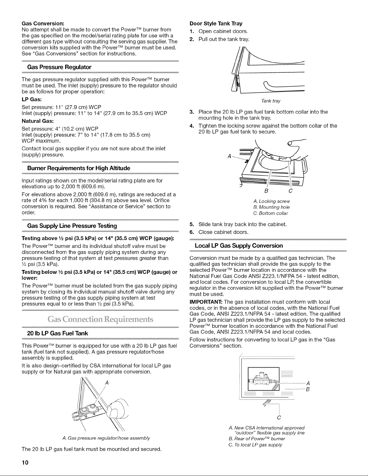
Door Style Tank Tray
1. Open cabinet doors.
2. Pull out the tank tray.
Tank tray
3. Place the 20 Ib LP gas fuel tank bottom collar into the
mounting hole in the tank tray.
4. Tighten the locking screw against the bottom collar of the
20 Ib LP gas fuel tank to secure.
B C
A. Locking screw
B. Mounting hole
C. Bottom collar
Gas Supply Line Pressure Testing
Testing above 1/2psi (3.5 kPa) or 14" (35.5 cm) WCP (gauge):
The Power TM burner and its individual shutoff valve must be
disconnected from the gas supply piping system during any
pressure testing of that system at test pressures greater than
1/2psi (3.5 kPa).
Testing below 1/2psi (3.5 kPa) or 14" (35.5 cm) WOP (gauge) or
lower:
The Power TM burner must be isolated from the gas supply piping
system by closing its individual manual shutoff valve during any
pressure testing of the gas supply piping system at test
pressures equal to or less than 1/2psi (3.5 kPa).
20 Ib LP Gas Fuel Tank
This Power TM burner is equipped for use with a 20 Ib LP gas fuel
tank (fuel tank not supplied). A gas pressure regulator/hose
assembly is supplied.
It is also design-certified by CSA International for local LP gas
supply or for Natural gas with appropriate conversion.
A
5. Slide tank tray back into the cabinet.
6. Close cabinet doors.
Local LP Gas Supply Conversion
Conversion must be made by a qualified gas technician. The
qualified gas technician shall provide the gas supply to the
selected Power TM burner location in accordance with the
National Fuel Gas Code ANSI Z223.1/NFPA 54 - latest edition,
and local codes. For conversion to local LP, the convertible
regulator in the conversion kit supplied with the Power TM burner
must be used.
IMPORTANT: The gas installation must conform with local
codes, or in the absence of local codes, with the National Fuel
Gas Code, ANSI Z223.1/NFPA 54 - latest edition. The qualified
LP gas technician shall provide the LP gas supply to the selected
Power TM burner location in accordance with the National Fuel
Gas Code, ANSI Z223.1/NFPA 54 and local codes.
Follow instructions for converting to local LP gas in the "Gas
Conversions" section.
\
A. Gaspressure regulator/hose assembly
The 20 Ib LP gas fuel tank must be mounted and secured.
10
C
A. New CSA International approved
"outdoor" flexiblegas supply line
B. Rear of Power TM burner
C. Tolocal LP gassupply
The gas supply line shall be equipped with an approved shutoff
valve. This valve should be located in the same area as the
Power TM burner and should be in a location that allows ease of
opening and closing. Do not block access to the shutoff valve.
The valve is for turning on or shutting off gas to the Power TM
burner.
B
A
instructions for converting to Natural gas in the "Gas
Conversions" section.
_:::::::::::::::::::::) _ ,
C
A. Gas supply line
B. Shutoff valve "open" position
C. To Power TM burner
Natural Gas Conversion
Conversion must be made by a qualified gas technician. The
qualified Natural gas technician shall provide the Natural gas
supply to the selected Power TM burner location in accordance
with the National Fuel Gas Code ANSI Z223.1/NFPA 54 - latest
edition, and local codes. For conversion to Natural gas, the
Natural gas conversion kit supplied with the Power TM burner
must be used.
IMPORTANT: The gas installation must conform with local
codes, or in the absence of local codes, with the National Fuel
Gas Code, ANSI Z223.1/NFPA 54 - latest edition.
To convert to Natural gas, the Natural Gas Conversion Kit
supplied with the Power TM burner must be used. Follow
INSTALLATION INSTRUCTIONS
A. New CSA International approved
"outdoor" flexible gas supply fine
B. Rear of Power TM burner
C. To Natural gas supply
The gas supply line shall be equipped with an approved shutoff
valve. This valve should be located in the same area as the
Power TM burner and should be in a location that allows ease of
opening and closing. Do not block access to the shutoff valve.
The valve is for turning on or shutting off gas to the Power TM
burner.
B
A. Gas supply line
B. Shutoff valve "open" position
C. To Power TM burner
Excessive Weight Hazard
Use two or more people to move and install side
burner.
Failure to do so can result in back or other injury.
Unpack Power TM burner. Remove all packaging materials and
remove Power TM burner from carton.
Place Power TM burner into outdoor enclosure, but leave
enough room in back to connect to gas supply and electrical
single prong plug-in.
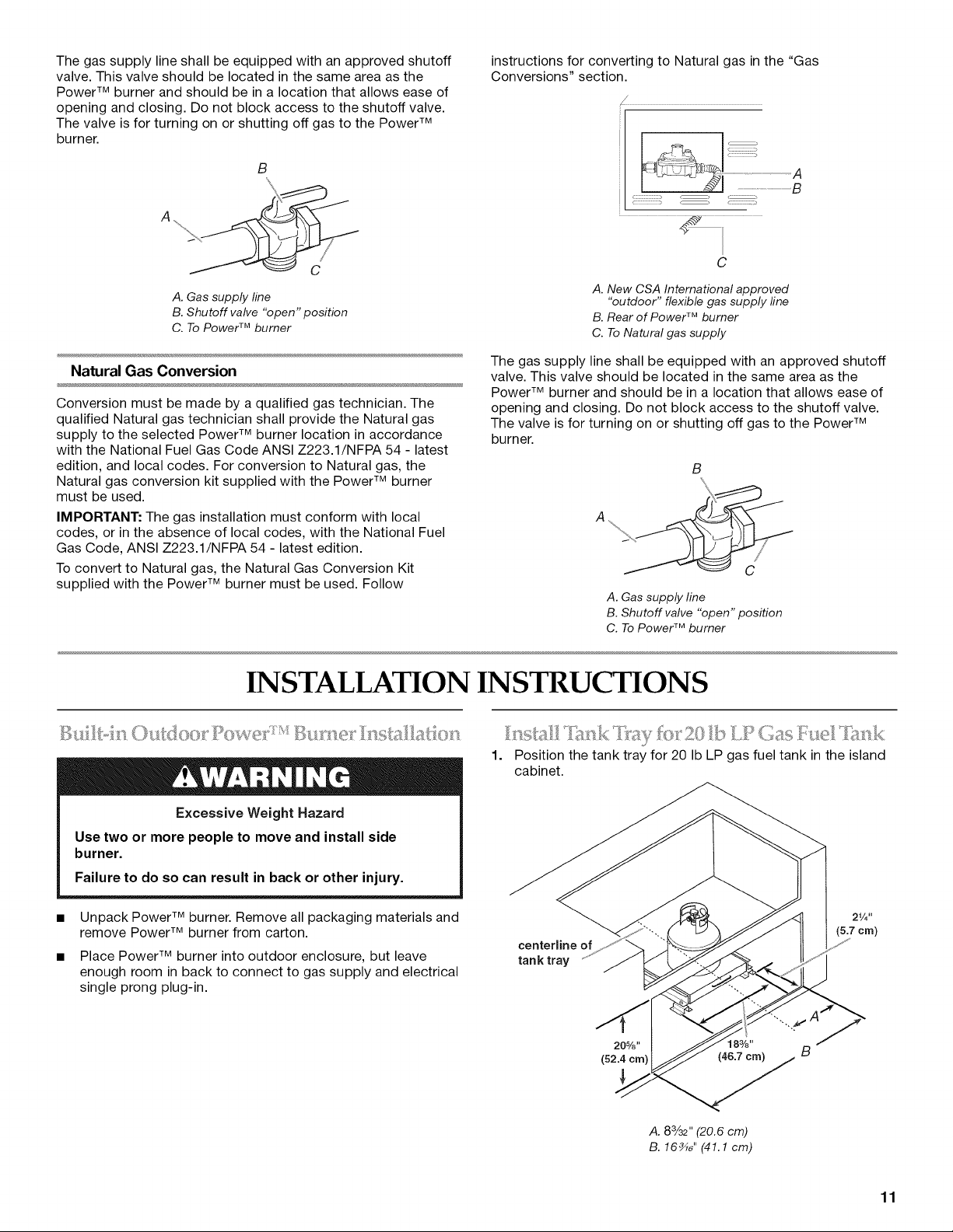
1. Position the tank tray for 20 Ib LP gas fuel tank in the island
cabinet.
21/4 It
centerline of
tank tray
20%"
(52.4 crn)
18%"
A. 8%2" (20.6 cm)
B. 16_" (41.1 cm)
(5.7 crn)
B
11
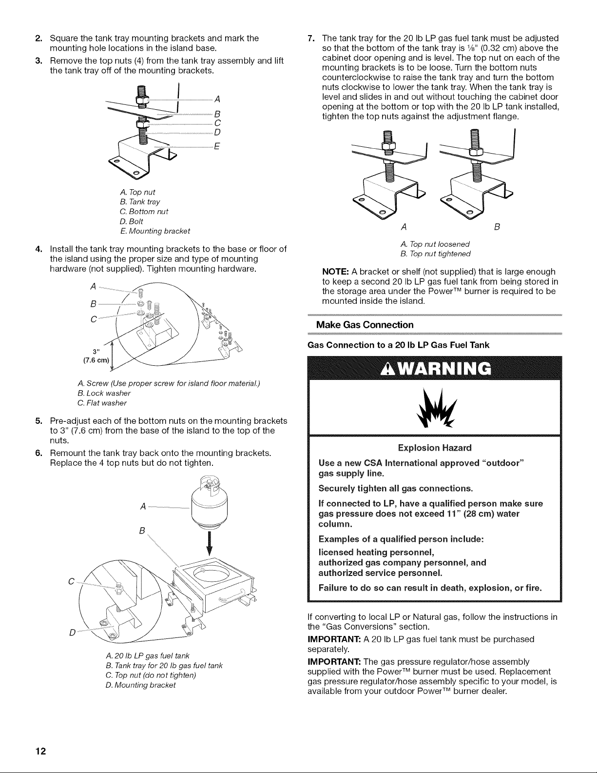
2. Square the tank tray mounting brackets and mark the
mounting hole locations in the island base.
3. Remove the top nuts (4) from the tank tray assembly and lift
the tank tray off of the mounting brackets.
A. Top nut
B. Tank tray
C. Bottom nut
D. Bolt
E. Mounting bracket
4.
Install the tank tray mounting brackets to the base or floor of
the island using the proper size and type of mounting
hardware (not supplied). Tighten mounting hardware.
A
g /
/
7.
The tank tray for the 20 Ib LP gas fuel tank must be adjusted
so that the bottom of the tank tray is %" (0.32 cm) above the
cabinet door opening and is level. The top nut on each of the
mounting brackets is to be loose. Turn the bottom nuts
counterclockwise to raise the tank tray and turn the bottom
nuts clockwise to lower the tank tray. When the tank tray is
level and slides in and out without touching the cabinet door
opening at the bottom or top with the 20 Ib LP tank installed,
tighten the top nuts against the adjustment flange.
B
A. Top nut loosened
B. Top nut tightened
NOTE: A bracket or shelf (not supplied) that is large enough
to keep a second 20 Ib LP gas fuel tank from being stored in
the storage area under the Power TM burner is required to be
mounted inside the island.
Make Gas Connection
A. Screw (Use proper screw for island floor material.)
B. Lock washer
C. Flat washer
5. Pre-adjust each of the bottom nuts on the mounting brackets
to 3" (7.6 cm) from the base of the island to the top of the
nuts.
6. Remount the tank tray back onto the mounting brackets.
Replace the 4 top nuts but do not tighten.
A. 20 Ib LP gas fuel tank
B. Tank tray for 20 Ib gas fuel tank
C. Top nut (do not tighten)
D. Mounting bracket
Gas Connection to a 20 Ib LPGas Fuel Tank
Explosion Hazard
Use a new CSA international approved "outdoor"
gas supply line.
Securely tighten all gas connections.
if connected to LP, have a qualified person make sure
gas pressure does not exceed 11" (28 cm) water
column.
Examples of a qualified person include:
licensed heating personnel,
authorized gas company personnel, and
authorized service personnel.
Failure to do so can result in death, explosion, or fire.
If converting to local LP or Natural gas, follow the instructions in
the "Gas Conversions" section.
IMPORTANT: A 20 Ib LP gas fuel tank must be purchased
separately.
IMPORTANT: The gas pressure regulator/hose assembly
supplied with the Power TM burner must be used. Replacement
gas pressure regulator/hose assembly specific to your model, is
available from your outdoor Power TM burner dealer.
12
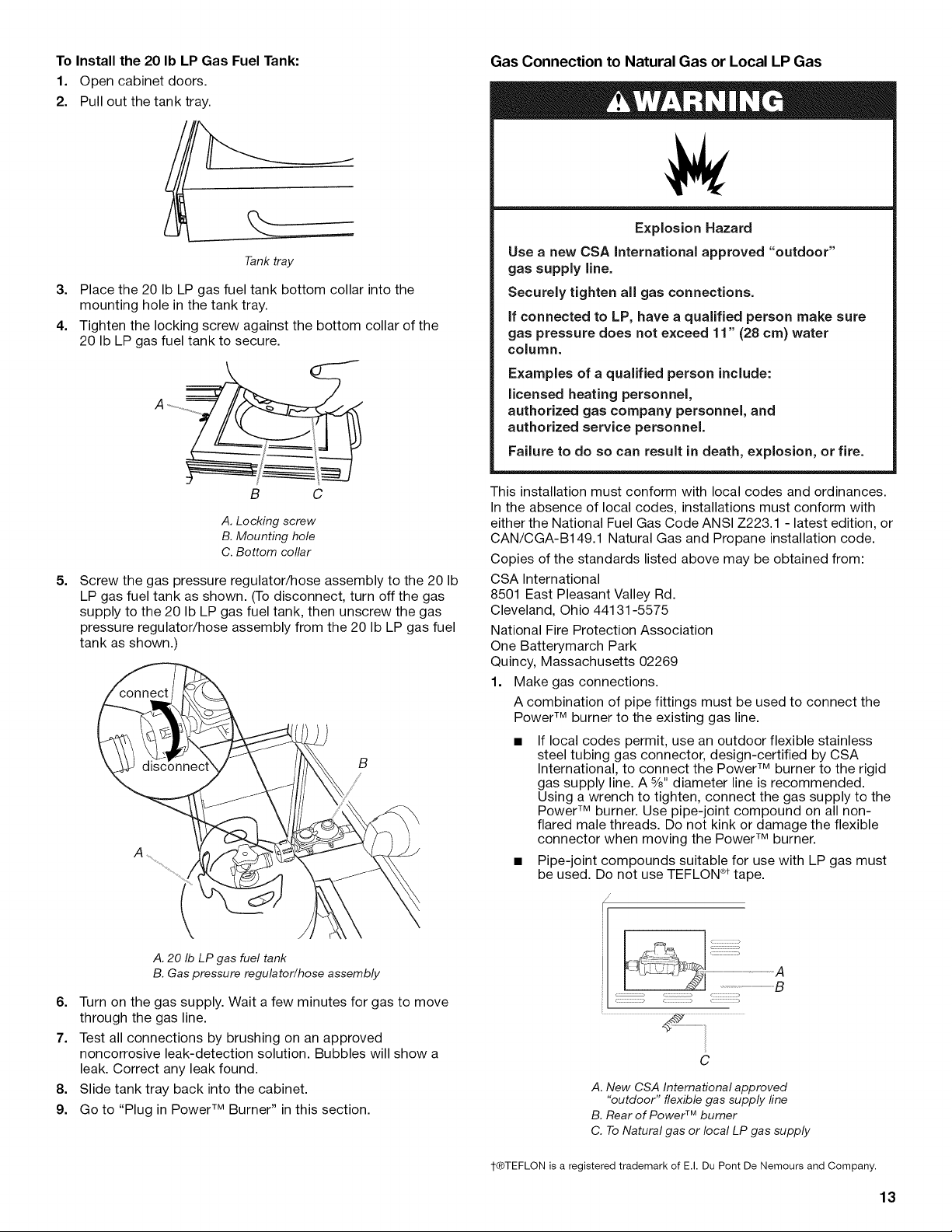
To Install the 20 Ib LP Gas Fuel Tank:
1. Open cabinet doors.
2. Pull out the tank tray.
Tank tray
3. Place the 20 Ib LP gas fuel tank bottom collar into the
mounting hole in the tank tray.
4. Tighten the locking screw against the bottom collar of the
20 Ib LP gas fuel tank to secure.
Gas Connection to Natural Gas or Local LP Gas
Explosion Hazard
Use a new CSA International approved "outdoor"
gas supply line.
Securely tighten all gas connections.
if connected to LP, have a qualified person make sure
gas pressure does not exceed 11" (28 cm) water
column.
Examples of a qualified person include:
licensed heating personnel,
authorized gas company personnel, and
authorized service personnel.
Failure to do so can result in death, explosion, or fire.
B C
A. Locking screw
B. Mounting hole
C. Bottom collar
5=
Screw the gas pressure regulator/hose assembly to the 20 Ib
LP gas fuel tank as shown. (To disconnect, turn off the gas
supply to the 20 Ib LP gas fuel tank, then unscrew the gas
pressure regulator/hose assembly from the 20 Ib LP gas fuel
tank as shown.
A
This installation must conform with local codes and ordinances.
In the absence of local codes, installations must conform with
either the National Fuel Gas Code ANSI Z223.1 - latest edition, or
CAN/CGA-B149.1 Natural Gas and Propane installation code.
Copies of the standards listed above may be obtained from:
CSA International
8501 East Pleasant Valley Rd.
Cleveland, Ohio 44131-5575
National Fire Protection Association
One Batterymarch Park
Quincy, Massachusetts 02269
1. Make gas connections.
A combination of pipe fittings must be used to connect the
Power TM burner to the existing gas line.
If local codes permit, use an outdoor flexible stainless
steel tubing gas connector, design-certified by CSA
International, to connect the Power TM burner to the rigid
gas supply line. A %" diameter line is recommended.
Using a wrench to tighten, connect the gas supply to the
Power TM burner. Use pipe-joint compound on all non-
flared male threads. Do not kink or damage the flexible
connector when moving the Power TM burner.
• Pipe-joint compounds suitable for use with LP gas must
be used. Do not use TEFLON ®ttape.
i/
i
A.20 Ib LP gas fuel tank
B.Gas pressure regulator/hose assembly
6. Turn on the gas supply. Wait a few minutes for gas to move
through the gas line.
7. Test all connections by brushing on an approved
noncorrosive leak-detection solution. Bubbles will show a
leak. Correct any leak found.
8. Slide tank tray back into the cabinet.
9. Go to "Plug in Power TM Burner" in this section.
C
A. New CSA International approved
"outdoor" flexible gas supply line
B. Rear of Power TM burner
C. To Natural gas or local LP gas supply
1-®TEFLON is a registered trademark of E.I. Du Pont De Nemours and Company.
13
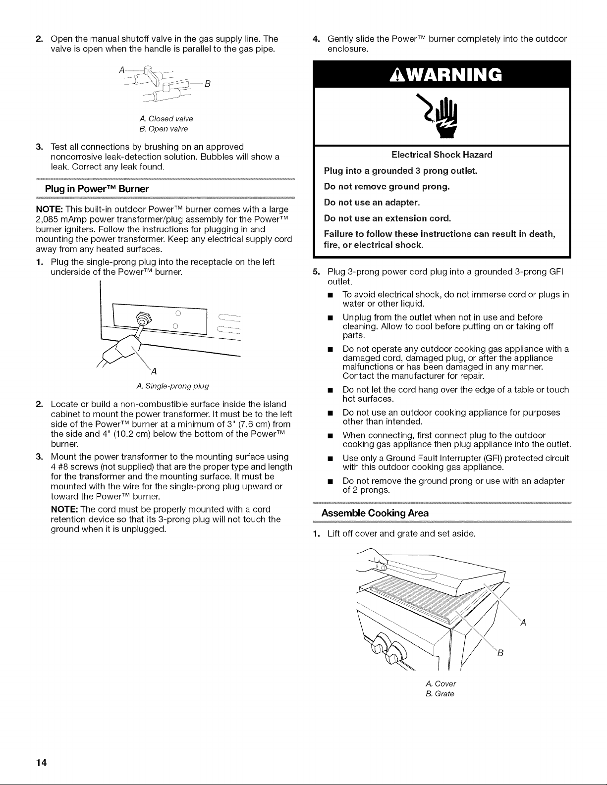
2. Open the manual shutoff valve in the gas supply line. The 4. Gently slide the Power TM burner completely into the outdoor
valve is open when the handle is parallel to the gas pipe. enclosure.
A. Closed valve
B. Open valve
3.
Test all connections by brushing on an approved
noncorrosive leak-detection solution. Bubbles will show a
leak. Correct any leak found.
Plug in Power TM Burner
NOTE: This built-in outdoor Power TM burner comes with a large
2,085 mAmp power transformer/plug assembly for the Power TM
burner igniters. Follow the instructions for plugging in and
mounting the power transformer. Keep any electrical supply cord
away from any heated surfaces.
Plug into a grounded 3 prong outlet.
Do not remove ground prong.
Do not use an adapter.
Do not use an extension cord.
Failure to follow these instructions can result in death,
fire, or electrical shock.
Electrical Shock Hazard
1. Plug the single-prong plug into the receptacle on the left
underside of the Power TM burner.
5.
Plug 3-prong power cord plug into a grounded 3-prong GFI
outlet.
• To avoid electrical shock, do not immerse cord or plugs in
water or other liquid.
• Unplug from the outlet when not in use and before
cleaning. Allow to cool before putting on or taking off
parts.
Do not operate any outdoor cooking gas appliance with a
damaged cord, damaged plug, or after the appliance
malfunctions or has been damaged in any manner.
Contact the manufacturer for repair.
A. Single-prong plug
2.
Locate or build a non-combustible surface inside the island
cabinet to mount the power transformer. It must be to the left
side of the Power TM burner at a minimum of 3" (7.6 cm) from
the side and 4" (10.2 cm) below the bottom of the Power TM
burner.
3.
Mount the power transformer to the mounting surface using
4 #8 screws (not supplied) that are the proper type and length
for the transformer and the mounting surface. It must be
mounted with the wire for the single-prong plug upward or
toward the Power TM burner.
NOTE: The cord must be properly mounted with a cord
retention device so that its 3-prong plug will not touch the
ground when it is unplugged.
• Do not let the cord hang over the edge of a table or touch
hot surfaces.
• Do not use an outdoor cooking appliance for purposes
other than intended.
When connecting, first connect plug to the outdoor
cooking gas appliance then plug appliance into the outlet.
Use only a Ground Fault Interrupter (GFI) protected circuit
with this outdoor cooking gas appliance.
Do not remove the ground prong or use with an adapter
of 2 prongs.
Assemble Cooking Area
1. Lift off cover and grate and set aside.
14
A. Cover
B. Grate
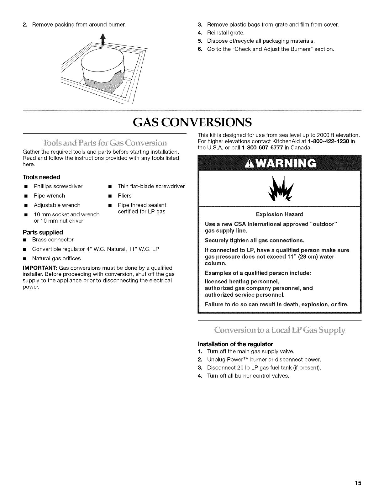
2. Remove packing from around burner. 3. Remove plastic bags from grate and film from cover.
4. Reinstall grate.
5. Dispose of/recycle all packaging materials.
6. Go to the "Check and Adjust the Burners" section.
GAS CONVERSIONS
This kit is designed for use from sea level up to 2000 ft elevation.
For higher elevations contact KitchenAid at 1-800-422-1230 in
Gather the required tools and parts before starting installation.
Read and follow the instructions provided with any tools listed
here.
Tools needed
• Phillips screwdriver
• Pipe wrench
• Adjustable wrench
• 10 mm socket and wrench
or 10 mm nut driver
• Thin flat-blade screwdriver
• Pliers
• Pipe thread sealant
certified for LP gas
Parts supplied
• Brass connector
• Convertible regulator 4" W.C. Natural, 11" W.C. LP
• Natural gas orifices
IMPORTANT: Gas conversions must be done by a qualified
installer. Before proceeding with conversion, shut off the gas
supply to the appliance prior to disconnecting the electrical
power.
the U.S.A. or call 1-800-607-6777 in Canada.
Explosion Hazard
Use a new CSA International approved "outdoor"
gas supply line.
Securely tighten all gas connections.
if connected to LP, have a qualified person make sure
gas pressure does not exceed 11" (28 cm) water
column.
Examples of a qualified person include:
licensed heating personnel,
authorized gas company personnel, and
authorized service personnel.
Failure to do so can result in death, explosion, or fire.
Installation of the regulator
1. Turn off the main gas supply valve.
2. Unplug Power TM burner or disconnect power.
3. Disconnect 20 Ib LP gas fuel tank (if present).
4. Turn off all burner control valves.
15
 Loading...