

Page 1

Ki|chen_kid _
BOTTOM-MOUNT BUILT-IN
REFRIGERATOR
........._,_ _ _,_ _;_
IMPORTANT: READ AND SAVE THESE INSTRUCTIONS. INSTALLATION REQUIRES 2 OR MORE PEOPLE.
REFRIGERADOR EMPOTRADO CON
CONGELADOR EN LA PARTE INFERIOR
IMPORTANTE: LEA Y GUARDE ESTAS INSTRUCCIONES. LA INSTALACION REQUIERE DE 20 MAS PERSONAS.
RI_FRIGI_RATEUR ENCASTRI_ AVEC
CONGELATEUR EN DESSOUS
IMPORTANT : LIRE ET CONSERVER CES INSTRUCTIONS. L'INSTALLATION NC:CESSITE L'INTERVENTION DE 2 PERSONNES OU PLUS.
Table of Contents/[ndice/Table des matieres .................................................................. 2
W10555564A
Page 2
TABLEOF CONTENTS
REFRIGERATOR SAFETY ............................................................. 3
MODELS .......................................................................................... 4
INSTALLATION REQUIREMENTS ................................................ 5
Tools and Parts ............................................................................ 5
Location Requirements ................................................................ 5
Electrical Requirements ............................................................... 6
Water Supply Requirements ........................................................ 6
Tipping Radius ............................................................................. 7
Product Dimensions ..................................................................... 8
Door Swing Dimensions ............................................................... 9
Overlay Series Door Panel and Cabinetry Clearance
(36" [91.4 cm] Models) ............................................................... 10
Overlay Series Door Panel and Cabinetry Clearance
(42' [106.7 cm] Models) ............................................................. 12
Overlay Series Custom Panels .................................................. 14
Custom Overlay Panel Dimensions ........................................... 14
Classic, Architect ®, and Overlay Series
Factory Panels and Kits (36" [91.4 cm] Models) ........................ 16
INDICE
SEGURIDAD DEL REFRIGERADOR ........................................... 29
MODELOS ..................................................................................... 30
REQUlSITOS DE INSTALACION ................................................. 31
Piezas y herramientas ................................................................ 31
Requisitos de ubicaci6n ............................................................. 31
Requisitos electricos .................................................................. 32
Requisitos del suministro de agua ............................................. 33
Arco de vuelco ........................................................................... 33
Medidas del producto ................................................................ 34
Medidas de oscilaci6n de la puerta ........................................... 35
Espacio para el panel de la puerta de la serie de paneles
recubiertos y para los armarios (modelos de 36" [91,4 cm]).....36
Espacio para el panel de la puerta de la serie de paneles
recubiertos y para los armarios (modelos de 42' [106,7 cm])...38
Paneles a la medida de la Serie de paneles recubiertos ........... 40
Dimensiones del panel recubierto a la medida ......................... 40
Paneles y juegos de fabrica para las
Series Classic, Architect®y de paneles recubiertos
(modelos de 36" [91,4 cm]) ....................................................... 42
Classic Series Custom Panels (36" [91.4 cm] Models) .............. 16
Classic and Architect ®Series Custom Side Panels ................... 17
Overlay Series Custom Side Panels .......................................... 18
INSTALLATION INSTRUCTIONS ................................................ 20
Unpack the Refrigerator ............................................................. 20
Reduce Tipping Radius .............................................................. 20
Move the Refrigerator into House .............................................. 20
Install Anti-Tip Boards ................................................................ 21
Connect the Water Supply ......................................................... 21
Plug in Refrigerator ..................................................................... 23
Move Refrigerator to Final Location ........................................... 23
Level and Align Refrigerator ....................................................... 23
Install Overlay and Classic Series Custom Panels .................... 24
Adjust Door(s) ............................................................................. 25
Install Side Panel ........................................................................ 27
Install Base Grille ........................................................................ 28
Complete Installation .................................................................. 28
Paneles a la medida para la Serie Classic
(modelos de 36" [91,4 cm]) ........................................................ 42
Paneles laterales a la medida para las
Series Classic y Architect ®......................................................... 43
Paneles laterales a la medida para la Serie de paneles
recubiertos .................................................................................. 44
INSTRUCCIONES DE INSTALACION ......................................... 46
Desempaque el refrigerador ...................................................... 46
C6mo reducir el arco de vuelco ................................................. 46
C6mo hacer entrar el refrigerador en la casa ............................ 46
C6mo instalarlos tableros antivuelco ........................................ 47
Conexi6n del suministro de agua .............................................. 47
C6mo enchufar el refrigerador ................................................... 49
C6mo mover el refrigerador a su ubicaci6n final ....................... 49
Nivelaci6n y alineamiento del refrigerador ................................. 49
C6mo instalar los paneles a la medida para las
Series de paneles recubiertos y Classic .................................... 50
Como ajustar la(s) puerta(s) ....................................................... 52
Como instalar el panel lateral ..................................................... 53
Como instalar la rejilla de la base .............................................. 54
Como terminar la instalacion ..................................................... 54
TABLEDES MATIERES
SECURITE DU REFRIGERATEUR .............................................. 55
MODELES ..................................................................................... 56
EXIGENCES D'INSTALLATION ................................................... 57
Outillage et pieces ...................................................................... 57
Exigences d'emplacement ......................................................... 57
Specifications electriques .......................................................... 58
Specifications de I'alimentation en eau ..................................... 59
Rayon de basculement .............................................................. 59
Dimensions du produit ............................................................... 60
Dimensions pour le pivotement des portes ............................... 61
Serie Panneaux decoratifs - Panneau de porte et placard -
dimensions et espace libre (modeles de 36" [91,4 cm])............ 62
Serie Panneaux decoratifs - Panneau de porte et placard -
dimensions et espace libre (modeles de 42" [106,7 cm]).......... 64
Panneaux personnalises de la serie Panneaux decoratifs ........66
Panneaux personnalises - Dimensions ...................................... 66
Ensembles de panneaux d'origine de la serie Classic
Architect ®et Panneaux decoratifs
(modeles de 36" [91,4 cm]) ........................................................ 68
2
Panneaux personnalises de la serie Classic
(modeles de 36" [91,4 cm]) ....................................................... 68
Panneaux lateraux personnalises des
series Classic et Architect ®........................................................ 69
Panneaux lateraux personnalises de la
serie Panneaux decoratifs .......................................................... 70
INSTRUCTIONS D'INSTALLATION ............................................. 72
Deballage du refrigerateur .......................................................... 72
Reduction du rayon de basculement ......................................... 72
Faire entrer le refrigerateur dans le domicile ............................. 72
Installation de planches antibasculement .................................. 73
Raccordement &I'alimentation en eau ...................................... 73
Branchement du refrigerateur .................................................... 75
Deplacement du refrigerateur & I'emplacement final................. 75
Reglage de I'aplomb et alignement du refrigerateur ................. 75
Installation des panneaux personnalises des
series Panneaux decoratifs et Classic ....................................... 76
Ajustement de la (des) porte(s) ................................................... 78
Installation du panneau lateral ................................................... 79
Installation de la grille de la base ............................................... 80
Achever I'installation .................................................................. 80
Page 3
REFRIGERATOR SAFETY
Your safety and the safety of others are very important.
We have provided many important safety messages in this manual and on your appliance. Always read and obey all safety
messages.
This is the safety alert symbol.
This symbol alerts you to potential hazards that can kill or hurt you and others.
All safety messages will follow the safety alert symbol and either the word "DANGER" or "WARNING."
These words mean:
You can be killed or seriously injured if you don't immediately
follow instructions.
You can be killed or seriously injured if you don't follow
instructions.
All safety messages will tell you what the potential hazard is, tell you how to reduce the chance of injury, and tell you what can
happen if the instructions are not followed.
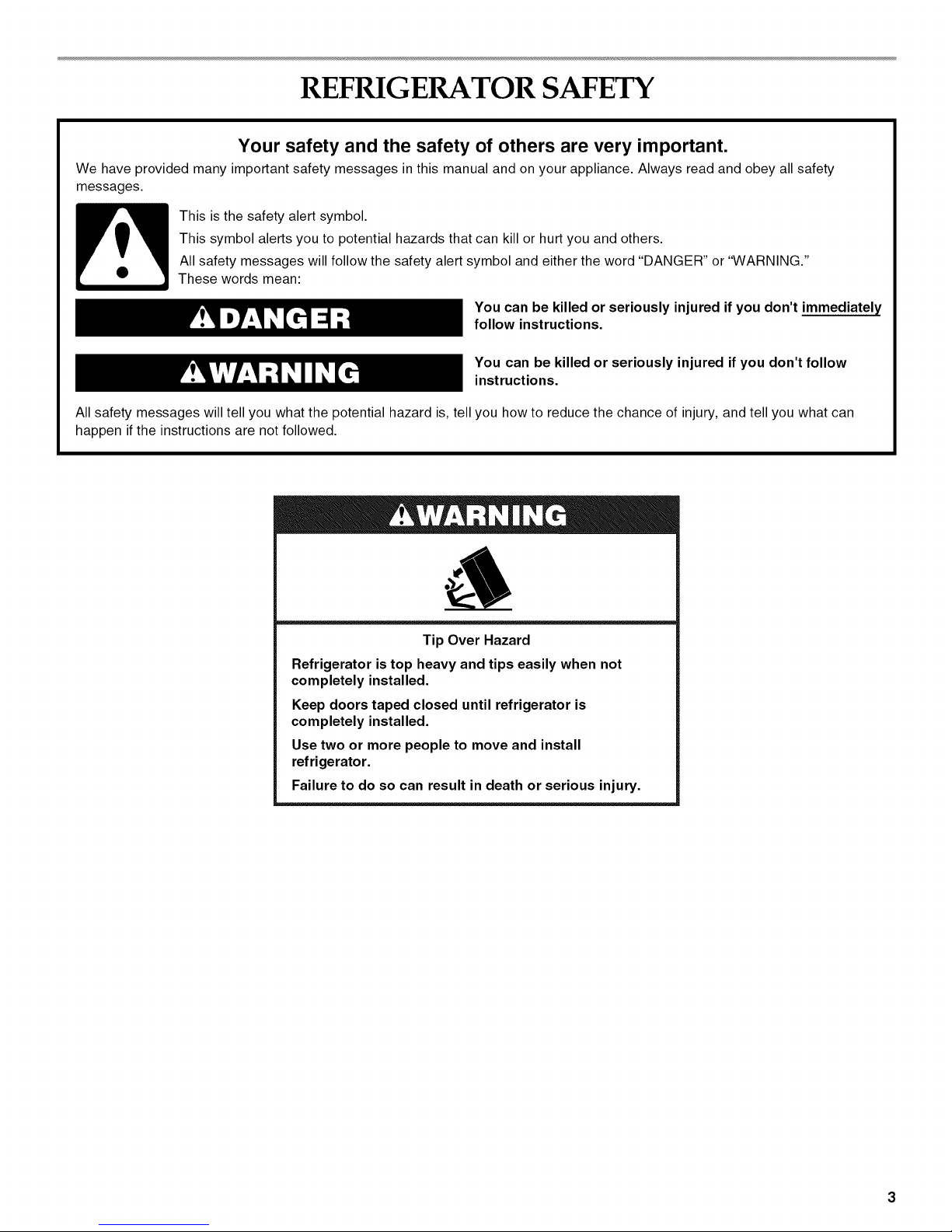
Tip Over Hazard
Refrigerator is top heavy and tips easily when not
completely installed.
Keep doors taped closed until refrigerator is
completely installed.
Use two or more people to move and install
refrigerator.
Failure to do so can result in death or serious injury.
Page 4
MODELS
C
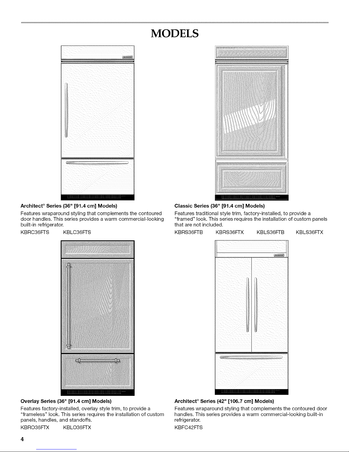
Architect _ Series (36" [91.4 cm] Models)
Features wraparound styling that complements the contoured
door handles. This series provides a warm commercial-looking
built-in refrigerator.
KBRC36FTS KBLC36FTS
Classic Series (36" [91.4 cm] Models)
Features traditional style trim, factory-installed, to provide a
"framed" look. This series requires the installation of custom panels
that are not included.
KBRS36FTB KBRS36FTX KBLS36FTB KBLS36FTX
Overlay Series (36" [91.4 cm] Models)
Features factory-installed, overlay style trim, to provide a
"frameless" look. This series requires the installation of custom
panels, handles, and standoffs.
KBRO36FTX KBLO36FTX
i i ii i
Architect ®Series (42" [106.7 cm] Models)
Features wraparound styling that complements the contoured door
handles. This series provides a warm commercial-looking built-in
refrigerator.
KBFC42FTS
Page 5
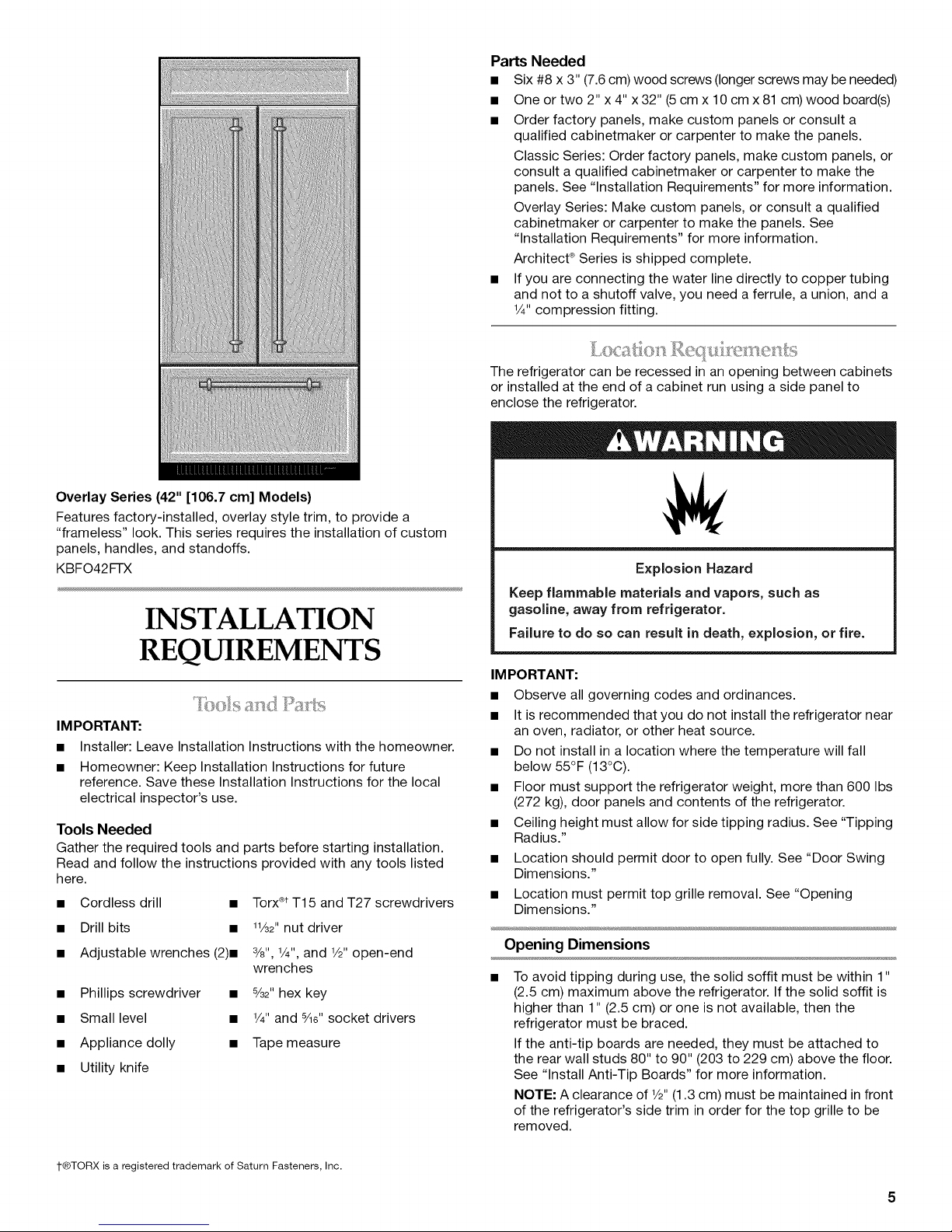
OverlaySeries(42" [106.7 cm] Models)
Features factory-installed, overlay style trim, to provide a
"frameless" look. This series requires the installation of custom
panels, handles, and standoffs.
KBFO42FTX
INSTALLATION
REQUIREMENTS
IMPORTANT:
• Installer: Leave Installation Instructions with the homeowner.
• Homeowner: Keep Installation Instructions for future
reference. Save these Installation Instructions for the local
electrical inspector's use.
Tools Needed
Gather the required tools and parts before starting installation.
Read and follow the instructions provided with any tools listed
here.
• Cordless drill •
• Drill bits •
• Adjustable wrenches (2)m
• Phillips screwdriver •
• Small level •
• Appliance dolly •
• Utility knife
Torx®tT15 and T27 screwdrivers
1½2"nut driver
3/8",1/4",and 1/2"open-end
wrenches
%2" hex key
1/4"and %e"socket drivers
Tape measure
Parts Needed
• Six #8 x 3" (7.6 cm) wood screws (longer screws may be needed)
• One or two 2" x 4" x 32" (5 cm x 10 cm x 81 cm) wood board(s)
• Order factory panels, make custom panels or consult a
qualified cabinetmaker or carpenter to make the panels.
Classic Series: Order factory panels, make custom panels, or
consult a qualified cabinetmaker or carpenter to make the
panels. See "Installation Requirements" for more information.
Overlay Series: Make custom panels, or consult a qualified
cabinetmaker or carpenter to make the panels. See
"Installation Requirements" for more information.
Architect ®Series is shipped complete.
• If you are connecting the water line directly to copper tubing
and not to a shutoff valve, you need a ferrule, a union, and a
1/4"compression fitting.
The refrigerator can be recessed in an opening between cabinets
or installed at the end of a cabinet run using a side panel to
enclose the refrigerator.
Explosion Hazard
Keep flammable materials and vapors, such as
gasoline, away from refrigerator.
Failure to do so can result in death, explosion, or fire.
IM PORTANT:
• Observe all governing codes and ordinances.
• It is recommended that you do not install the refrigerator near
an oven, radiator, or other heat source.
• Do not install in a location where the temperature will fall
below 55°F (13°C).
• Floor must support the refrigerator weight, more than 600 Ibs
(272 kg), door panels and contents of the refrigerator.
• Ceiling height must allow for side tipping radius. See "Tipping
Radius."
• Location should permit door to open fully. See "Door Swing
Dimensions."
• Location must permit top grille removal. See "Opening
Dimensions."
Opening Dimensions
To avoid tipping during use, the solid soffit must be within 1"
(2.5 cm) maximum above the refrigerator. Ifthe solid soffit is
higher than 1" (2.5 cm) or one is not available, then the
refrigerator must be braced.
If the anti-tip boards are needed, they must be attached to
the rear wall studs 80" to 90" (203 to 229 cm) above the floor.
See "Install Anti-Tip Boards" for more information.
NOTE: A clearance of 1/2"(1.3 cm) must be maintained in front
of the refrigerator's side trim in order for the top grille to be
removed.
t®TORX is a registered trademark of Saturn Fasteners, Inc.
Page 6
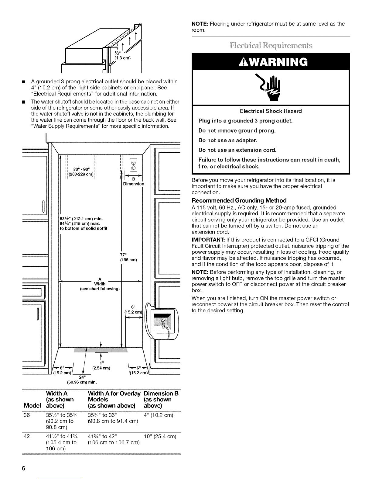
-- NOTE: Flooring under refrigerator must be at same level as the
A grounded 3 prong electrical outlet should be placed within
4" (10.2 cm) of the right side cabinets or end panel. See
"Electrical Requirements" for additional information.
The water shutoff should be located in the base cabinet on either
side of the refrigerator or some other easily accessible area. If
the water shutoff valve is not inthe cabinets, the plumbing for
the water line can come through the floor or the back wall. See
"Water Supply Requirements" for more specific information.
/
room.
£:i',1@CI /_,,@;]!
Electrical Shock Hazard
Plug into a grounded 3 prong outlet.
Do not remove ground prong.
Do not use an adapter.
Do not use an extension cord.
Failure to follow these instructions can result in death,
fire, or electrical shock.
0
0
831/2" (212.1 cm) min.
84%" (215 cm) max.
to bottom of solid soffit
A
Width
(see chart following)
t
Dimension
77"
(196 cm)
(15.2 cm'
Before you move your refrigerator into its final location, it is
important to make sure you have the proper electrical
connection.
Recommended Grounding Method
A 115 volt, 60 Hz., AC only, 15- or 20-amp fused, grounded
electrical supply is required. It is recommended that a separate
circuit serving only your refrigerator be provided. Use an outlet
that cannot be turned off by a switch. Do not use an
extension cord.
IMPORTANT: If this product is connected to a GFCI (Ground
Fault Circuit Interrupter) protected outlet, nuisance tripping of the
power supply may occur, resulting in loss of cooling. Food quality
and flavor may be affected. If nuisance tripping has occurred,
and if the condition of the food appears poor, dispose of it.
NOTE: Before performing any type of installation, cleaning, or
removing a light bulb, remove the top grille and turn the master
power switch to OFF or disconnect power at the circuit breaker
box.
When you are finished, turn ON the master power switch or
6 II
reconnect power at the circuit breaker box. Then reset the control
to the desired setting.
(2.54
1"cm) _,_ 6" •
l (15.2 c
24"
(60.96 cm) min.
Model
36
42
Width A
(as shown
above)
351/2"to 353/4"
(90.2 cm to
90.8 cm)
411/2"to 413/4"
(105.4 cm to
106 cm)
Width Afor Overlay Dimension B
Models (as shown
(as shown above) above)
353/4'' to 36" 4" (10.2 cm)
(90.8 cm to 91.4 cm)
413/4'' to 42" 10" (25.4 cm)
(106 cm to 106.7 cm)
6
Page 7
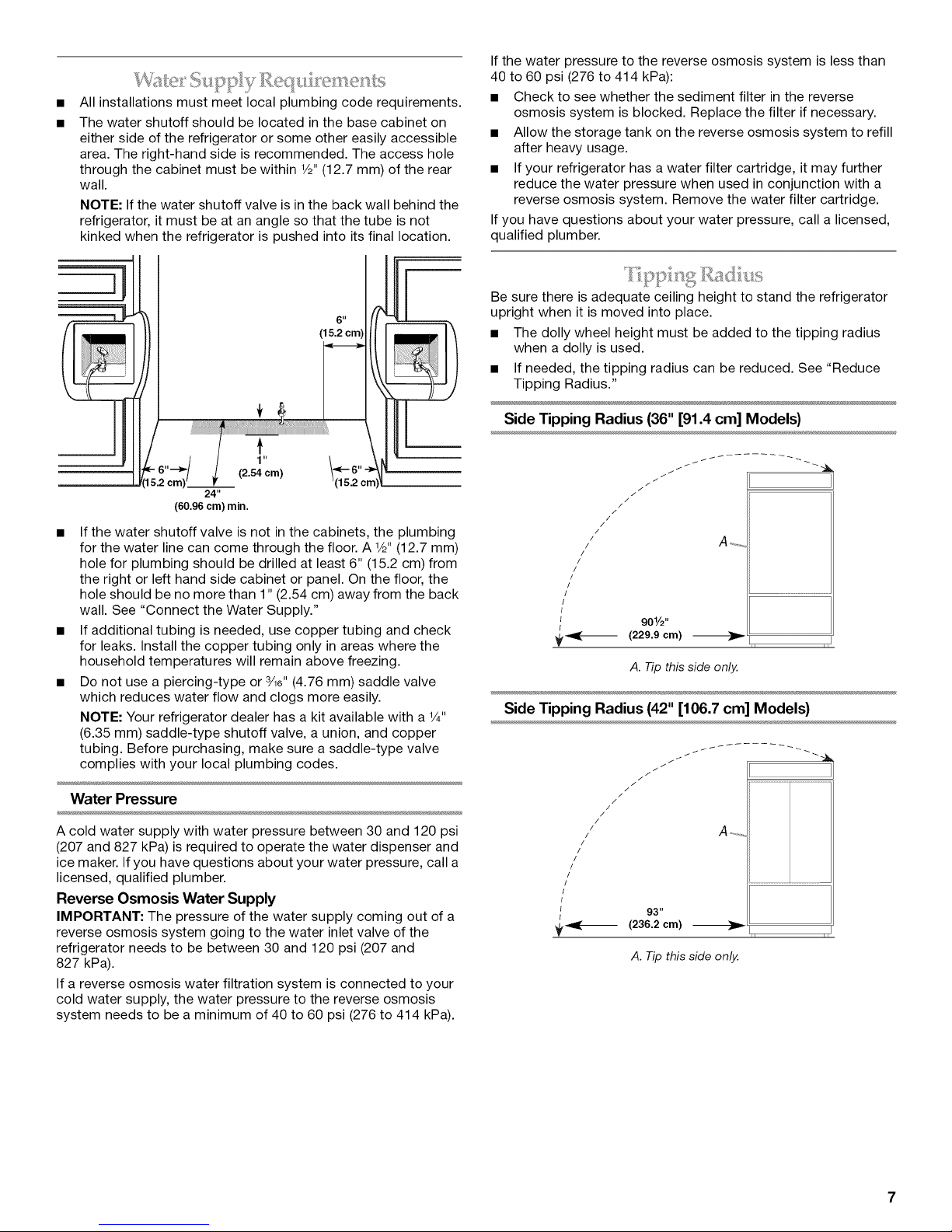
All installations must meet local plumbing code requirements.
The water shutoff should be located in the base cabinet on
either side of the refrigerator or some other easily accessible
area. The right-hand side is recommended. The access hole
through the cabinet must be within 1/2"(12.7 mm) of the rear
wall.
NOTE: If the water shutoff valve is in the back wall behind the
refrigerator, it must be at an angle so that the tube is not
kinked when the refrigerator is pushed into its final location.
6"
(15.2 cm)
24"
(60.96 cm) min.
• If the water shutoff valve is not in the cabinets, the plumbing
for the water line can come through the floor. A 1/2"(12.7 mm)
hole for plumbing should be drilled at least 6" (15.2 cm) from
the right or left hand side cabinet or panel. On the floor, the
hole should be no more than 1" (2.54 cm) away from the back
wall. See "Connect the Water Supply."
• If additional tubing is needed, use copper tubing and check
for leaks. Install the copper tubing only in areas where the
household temperatures will remain above freezing.
• Do not use a piercing-type or 3/le"(4.76 mm) saddle valve
which reduces water flow and clogs more easily.
NOTE: Your refrigerator dealer has a kit available with a 1/4"
(6.35 mm) saddle-type shutoff valve, a union, and copper
tubing. Before purchasing, make sure a saddle-type valve
complies with your local plumbing codes.
If the water pressure to the reverse osmosis system is less than
40 to 60 psi (276 to 414 kPa):
• Check to see whether the sediment filter in the reverse
osmosis system is blocked. Replace the filter if necessary.
• Allow the storage tank on the reverse osmosis system to refill
after heavy usage.
• If your refrigerator has a water filter cartridge, it may further
reduce the water pressure when used in conjunction with a
reverse osmosis system. Remove the water filter cartridge.
If you have questions about your water pressure, call a licensed,
qualified plumber.
Be sure there is adequate ceiling height to stand the refrigerator
upright when it is moved into place.
• The dolly wheel height must be added to the tipping radius
when a dolly is used.
• If needed, the tipping radius can be reduced. See "Reduce
Tipping Radius."
Side Tipping Radius (36" [91.4 cm] Models)
/
J
J
/
/
/
/
/
/
/
/
/
!
/ A +,,,,
//
/
/
//
/ .............................................
/
/
(
_-_ (229.9 cm) _
901/2,,
ii ii
A. Tip this side only.
Side Tipping Radius (42" [106.7 cm] Models)
Water Pressure
A cold water supply with water pressure between 30 and 120 psi
(207 and 827 kPa) is required to operate the water dispenser and
ice maker. If you have questions about your water pressure, call a
licensed, qualified plumber.
Reverse Osmosis Water Supply
IMPORTANT: The pressure of the water supply coming out of a
reverse osmosis system going to the water inlet valve of the
refrigerator needs to be between 30 and 120 psi (207 and
827 kPa).
If a reverse osmosis water filtration system is connected to your
cold water supply, the water pressure to the reverse osmosis
system needs to be a minimum of 40 to 60 psi (276 to 414 kPa).
ii ii
A. Tip this side only.
Page 8
I;_[0_.4111Ctl51.9_ISQIS_:,,(} 15
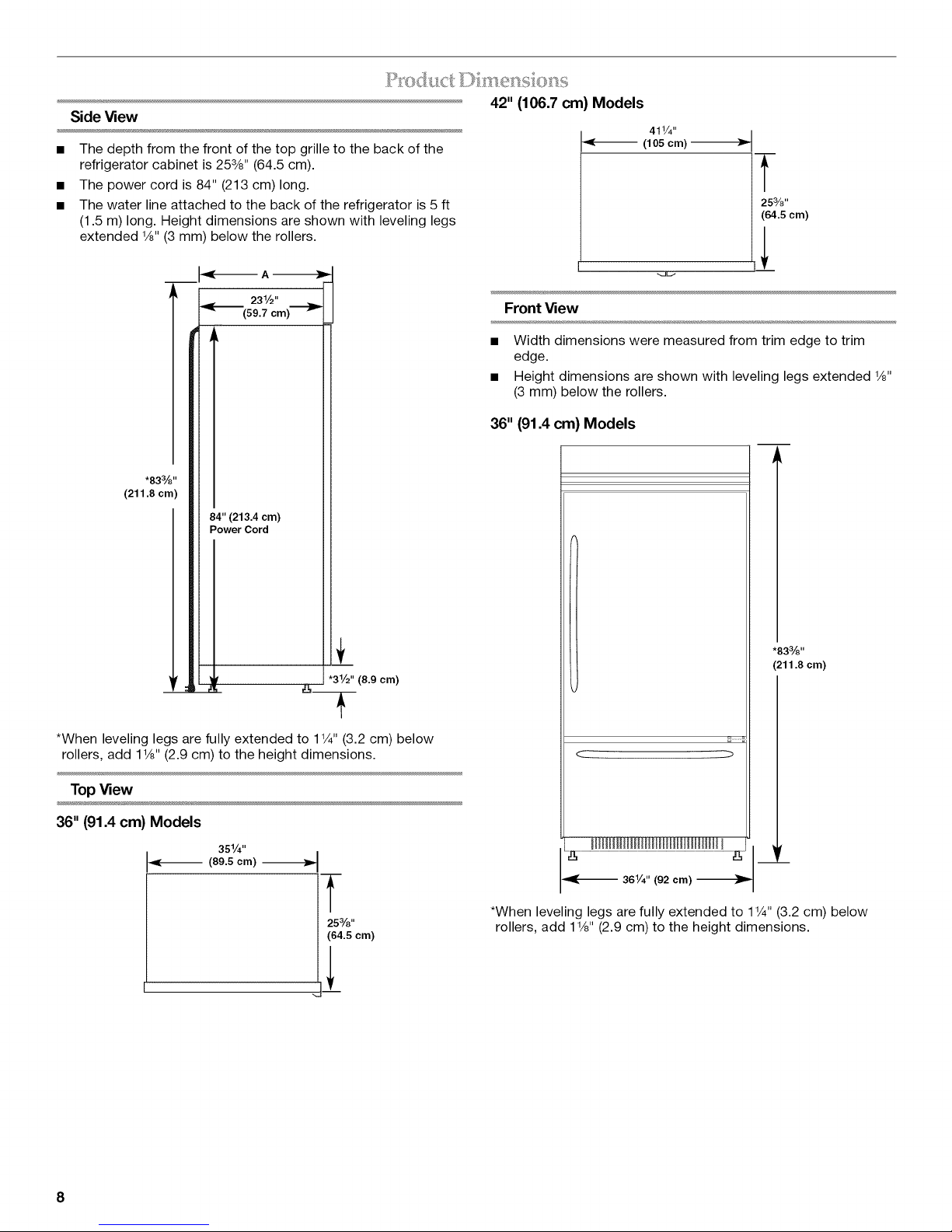
Side View
• The depth from the front of the top grille to the back of the
refrigerator cabinet is 253/8'' (64.5 cm).
• The power cord is 84" (213 cm) long.
• The water line attached to the back of the refrigerator is 5 ft
(1.5 m) long. Height dimensions are shown with leveling legs
extended 1/8"(3 mm) below the rollers.
A
231/2"
(59.7 cm)
.833/8"
(211.8 cm)
84" (213.4 cm)
Power Cord
42" (106.7 cm) Models
411/4"
(105 cm)
T
253/8"
(64.5 cm)
Front View
Width dimensions were measured from trim edge to trim
edge.
Height dimensions are shown with leveling legs extended 1/8"
(3 mm) below the rollers.
36" (91.4 cm) Models
T
*When leveling legs are fully extended to 1V4" (3.2 cm) below
rollers, add 1V8" (2.9 cm) to the height dimensions.
"31/2" (8.9 cm)
TopView
36" (91.4 cm) Models
351/4"
(89.5 cm)
T
253/8"
(64.5 cm)
.833/8 ,,
(211.8 cm)
< >
jr
_-- 361/4" (92 cm)
*When leveling legs are fully extended to 1V4" (3.2 cm) below
rollers, add 1V8" (2.9 cm) to the height dimensions.
8
Page 9
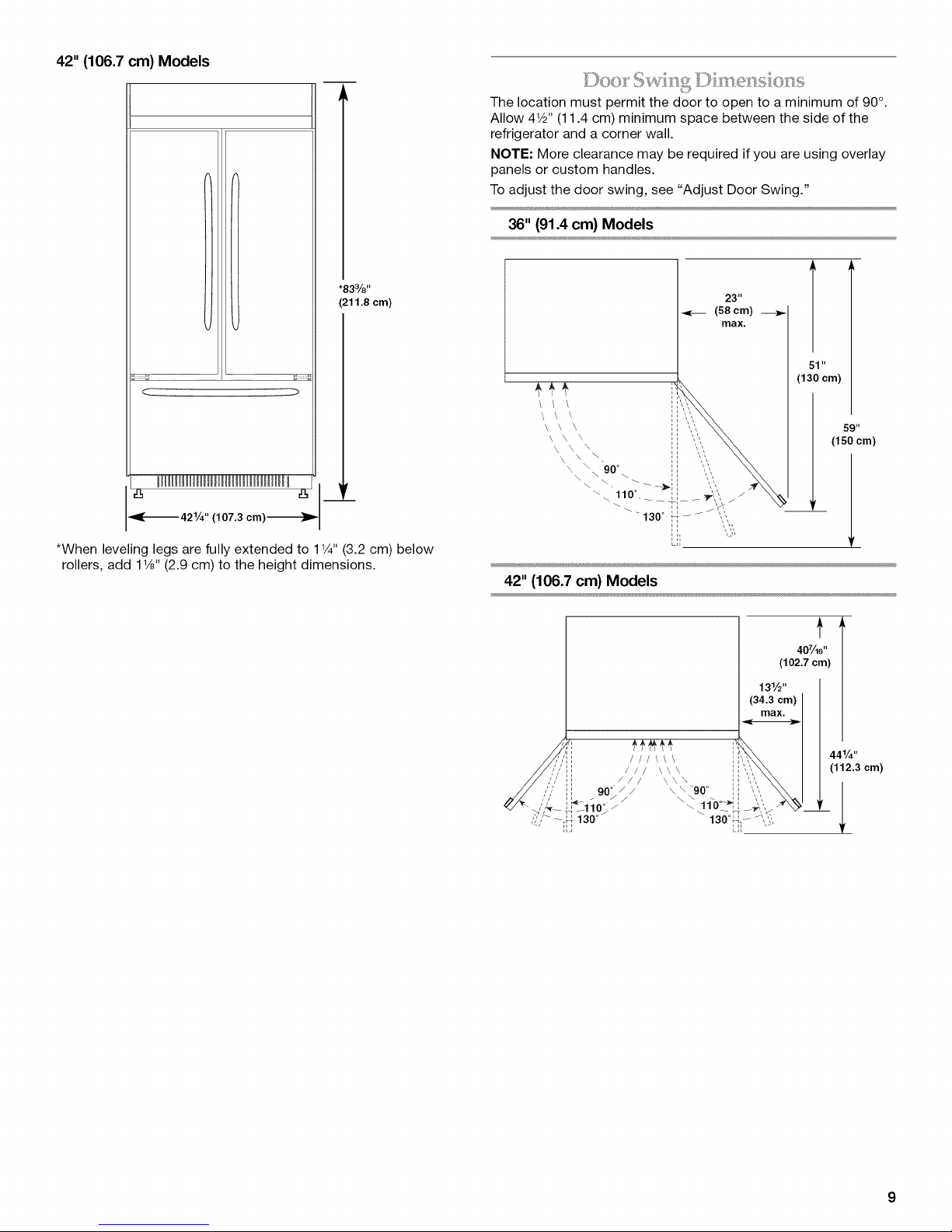
42"(106.7cm)Models
.......... ( ..................
The location must permit the door to open to a minimum of 90°.
Allow 4W' (11.4 cm) minimum space between the side of the
refrigerator and a corner wall.
NOTE: More clearance may be required if you are using overlay
panels or custom handles.
To adjust the door swing, see "Adjust Door Swing."
36" (91.4 cm) Models
*83%"
(211.8 cm)
< >
(107.3 cm)_ --421/4"
*When leveling legs are fully extended to 1V4" (3.2 cm) below
rollers, add 1V8" (2.9 cm) to the height dimensions.
23 u
_-_ (58 cm)
max.
_9 u
(150 cm)
42" (106.7 cm) Models
t
407/_6''
(102.7 cm)
441/4''
(112.3 cm)
Page 10
__,___J_c.__._y__,J___0_Deo_'.•_....._....._a_sei_a_sd(_abi__:_ _( _a_'a_sc_ G6" _/_lj_,_._c:_:___________'_
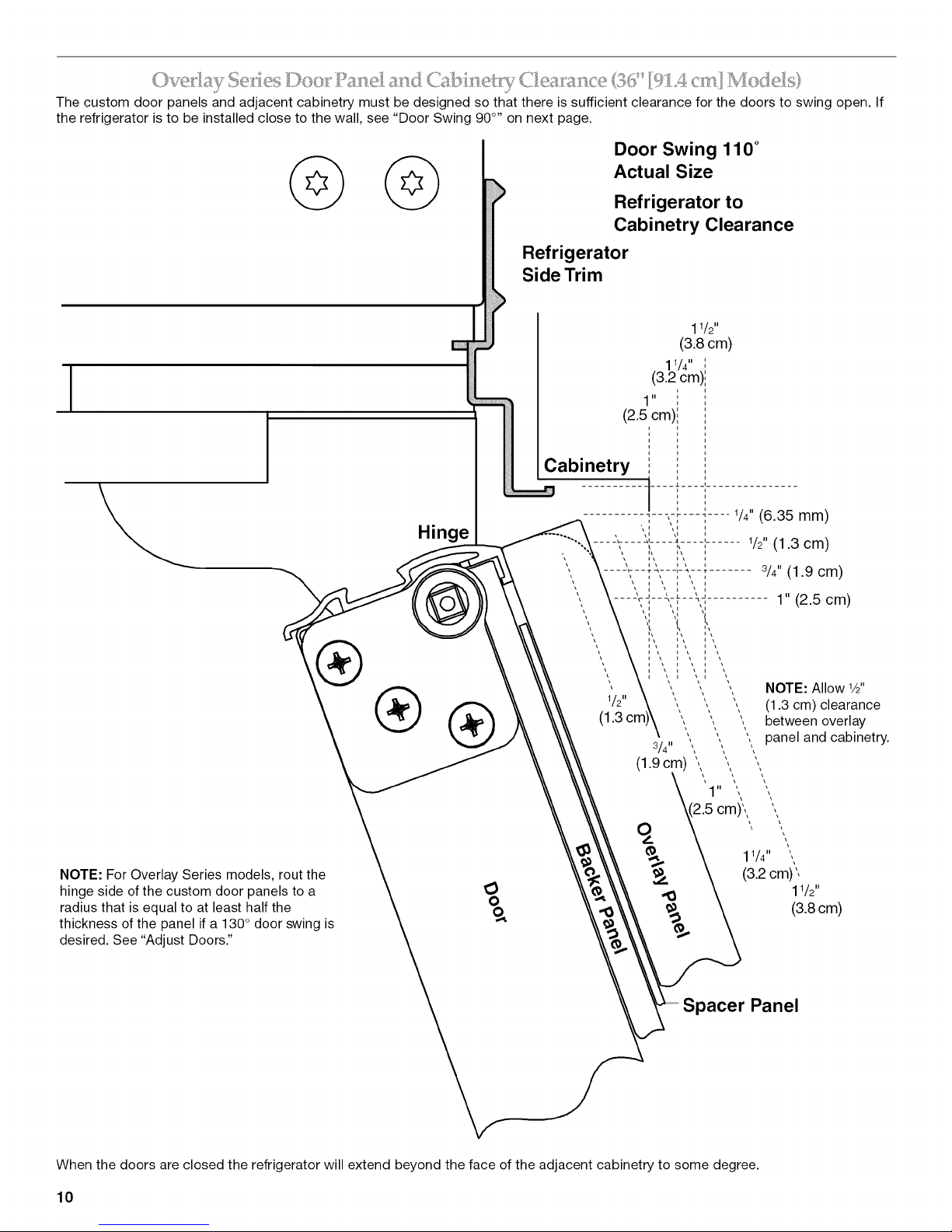
The custom door panels and adjacent cabinetry must be designed so that there is sufficient clearance for the doors to swing open. If
the refrigerator is to be installed close to the wall, see "Door Swing 90 °,' on next page.
Door Swing 110 °
Actual Size
Refrigerator to
Cabinetry Clearance
Refrigerator
Side Trim
Hinge
®
NOTE: For Overlay Series models, rout the
hinge side of the custom door panels to a
radius that is equal to at least half the
thickness of the panel if a 130° door swing is
desired. See "Adjust Doors."
When the doors are closed the refrigerator will extend beyond the face of the adjacent cabinetry to some degree.
Panel
10
Page 11
I
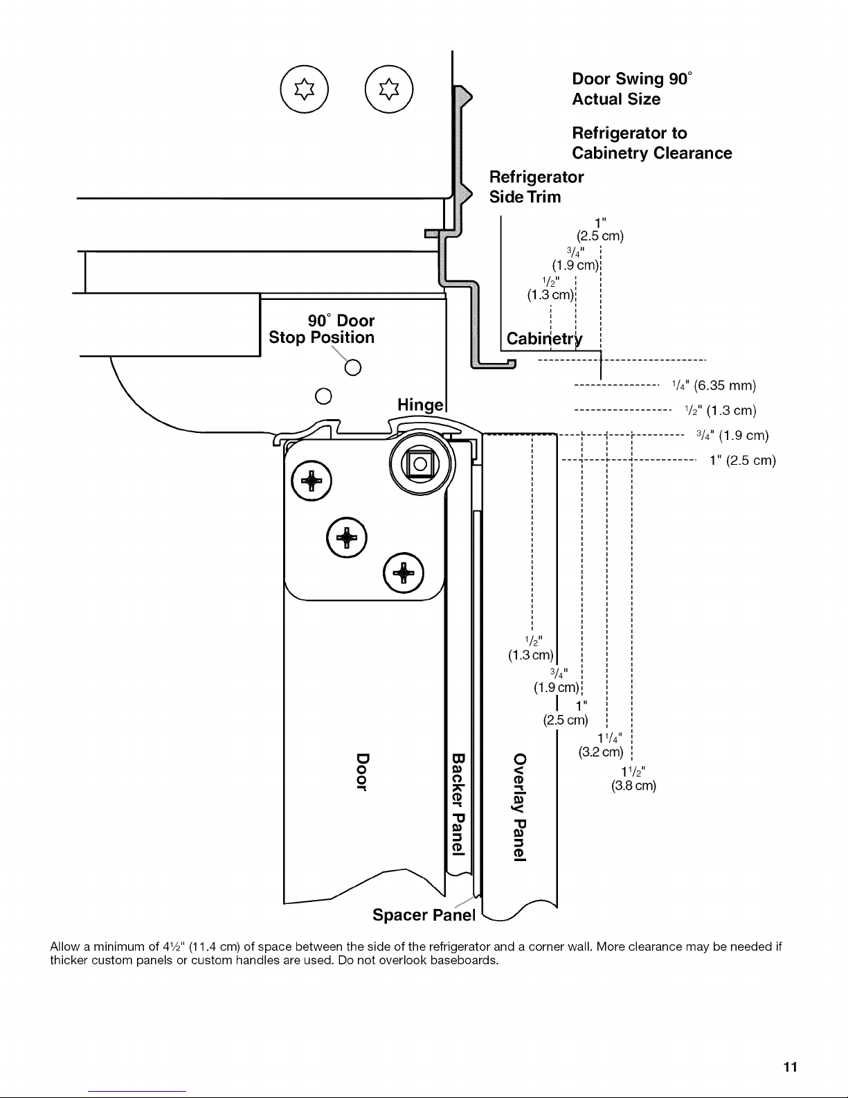
90° Door
Stop Position
Refrigerator
Side Trim
(1.9 cm)
/2 ',
(1.3,cm)i
,, ,,
i i
i i
Cabin,'etr_/
Door Swing 90°
Actual Size
Refrigerator to
Cabinetry Clearance
,1
(2.5 cm)
3/4"
O
Hinge
1/2"
(1.30m)
(1.90m) i
0
<
"--II
m
,<
"0
1/4"(6.35 mm)
1/2"(1.3 cm)
3/4"(1.9 cm)
1" (2.5 cm)
3/4"
I 1"
(2.5cm)
11/4"
(3.2 cm)
11/2"
(3.8cm)
Allow a minimum of 41/2"(11.4 cm) of space between the side of the refrigerator and a corner wall. More clearance may be needed if
thicker custom panels or custom handles are used. Do not overlook baseboards.
jj'_
Spacer Panel
11
Page 12
....._.._._._" <_..,,,,_..-_..._,__0_ ....._-_,• .<. ' _'_.4._......_"-<_ _'_ II_O6.T__ __o__4_
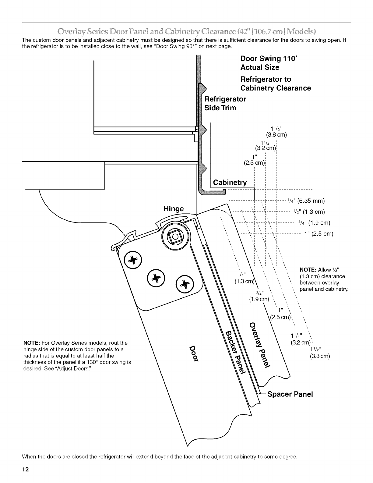
The custom door panels and adjacent cabinetry must be designed so that there is sufficient clearance for the doors to swing open. If
the refrigerator is to be installed close to the wall, see "Door Swing 90 °,' on next page.
Door Swing 110 °
Actual Size
Refrigerator to
Cabinetry Clearance
Refrigerator
Side Trim
I
I
[
NOTE: For Overlay Series models, rout the
hinge side of the custom door panels to a
radius that is equal to at least half the
thickness of the panel if a 130° door swing is
desired. See "Adjust Doors."
Hinge
®
When the doors are closed the refrigerator will extend beyond the face of the adjacent cabinetry to some degree.
12
Panel
Page 13
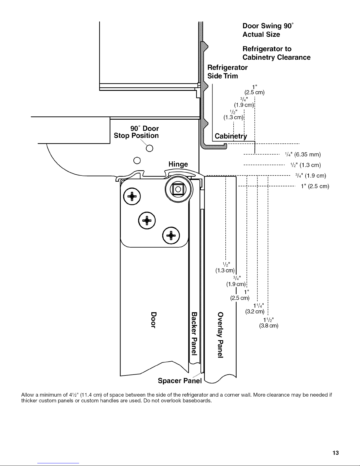
90° Door
Stop Position
O Hinge
Refrigerator
Side Trim
I
I
[
3/4"
(1.9 cm)
1 II I
/2 ,,
(1.3 cm),,
i '
i i
,, ,,
Cabin_etr_
Door Swing 90 °
Actual Size
Refrigerator to
Cabinetry Clearance
11
(2.5 cm)
i
1/4" (6.35 mm)
1/2" (1.3 cm)
®
®
......... r ......... 3/4" (1.9 cm)
i
1" (2.5 cm)
1/2"
(1.3 cm)
3/4"
(1.90m) i
I 1"
(2.5ore)
11/4"
O
O
"=l
O
<
"=l
i
,<
"O
(3.2 cm)
11/2"
(3.8cm)
Allow a minimum of 41/2"(11.4 cm) of space between the side of the refrigerator and a corner wall. More clearance may be needed if
thicker custom panels or custom handles are used. Do not overlook baseboards.
i
Spacer Panel
13
Page 14
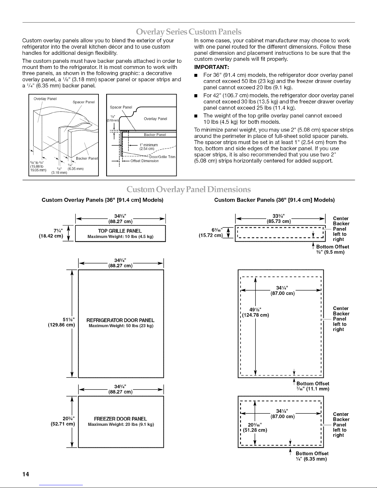
Custom overlay panels allow you to blend the exterior of your
refrigerator into the overall kitchen decor and to use custom
handles for additional design flexibility.
The custom panels must have backer panels attached in order to
mount them to the refrigerator. It is most common to work with
three panels, as shown in the following graphic: a decorative
overlay panel, a 1/8"(3.18 mm) spacer panel or spacer strips and
a 1/4" (6.35 mm) backer panel.
Overlay Panel
Spacer Panel
I
Spacer
8i_ _ Over'ayPane'JS"
-i i
_ 1" minimum
i I /264cm .......
5/s"to 3/4"
(15.88 to
19.05 ram)
1/s" (6.35 ram)
(3.18 ram)
Custom Overlay Panels (36" [91.4 cm] Models) Custom Backer Panels (36" [91.4 cm] Models)
Backer Panel
1/4"
I _Deor/Grille Trim
-_ Offset Dimension
343/4''
(88.27 cm) _- _ 333/4"(85.73 cm) _ Center
In some cases, your cabinet manufacturer may choose to work
with one panel routed for the different dimensions. Follow these
panel dimension and placement instructions to be sure that the
custom overlay panels will fit properly.
IM PORTANT:
• For 36" (91.4 cm) models, the refrigerator door overlay panel
cannot exceed 50 Ibs (23 kg) and the freezer drawer overlay
panel cannot exceed 20 Ibs (9.1 kg).
• For 42" (106.7 cm) models, the refrigerator door overlay panel
cannot exceed 30 Ibs (13.5 kg) and the freezer drawer overlay
panel cannot exceed 25 Ibs (11.4 kg).
• The weight of the top grille overlay panel cannot exceed
10 Ibs (4.5 kg) for both models.
To minimize panel weight, you may use 2" (5.08 cm) spacer strips
around the perimeter in place of full-sheet solid spacer panels.
The spacer strips must be set in at least 1" (2.54 cm) from the
top, bottom and side edges of the backer panel. If you use
spacer strips, it is also recommended that you use two 2"
(5.08 cm) strips horizontally centered for added support.
Backer
71/4"T I TOP GRILLE PANEL 1 6a/_e"---_- I_ _,o,o, Panel
(18.42cm) __h I (15.72 cm)_L [' _t _j leftto
MaximumWeight: 10Ibs (4.5 kg) = right
_' Bottom Offset
%" (9.5 mm)
343/4"
(88.27 cm)
f
(87.00 cm)
Center
Backer
,,,,,,,,Panel
left to
right
I
Center
', Backer
Panel
I left to
|
I right
51W'
(129.86 cm)
203/4''
(52.71 cm)
REFRIGERATOR DOOR PANEL
MaximumWeight: 50 Ibs (23 kg)
'r
343/4 ''
(88.27 cm)
T
FREEZER DOOR PANEL
Maximum Weight: 20 robs(9.1 kg)
49W'
(124.78 cm)
= =
--I
203/1e"
(51.28 cm)
t
_ Bottom Offset
Y_6"(11.1 mm)
34V4"
(87.00 cm)
_ Bottom Offset
V4"(6.35 ram)
14
Page 15
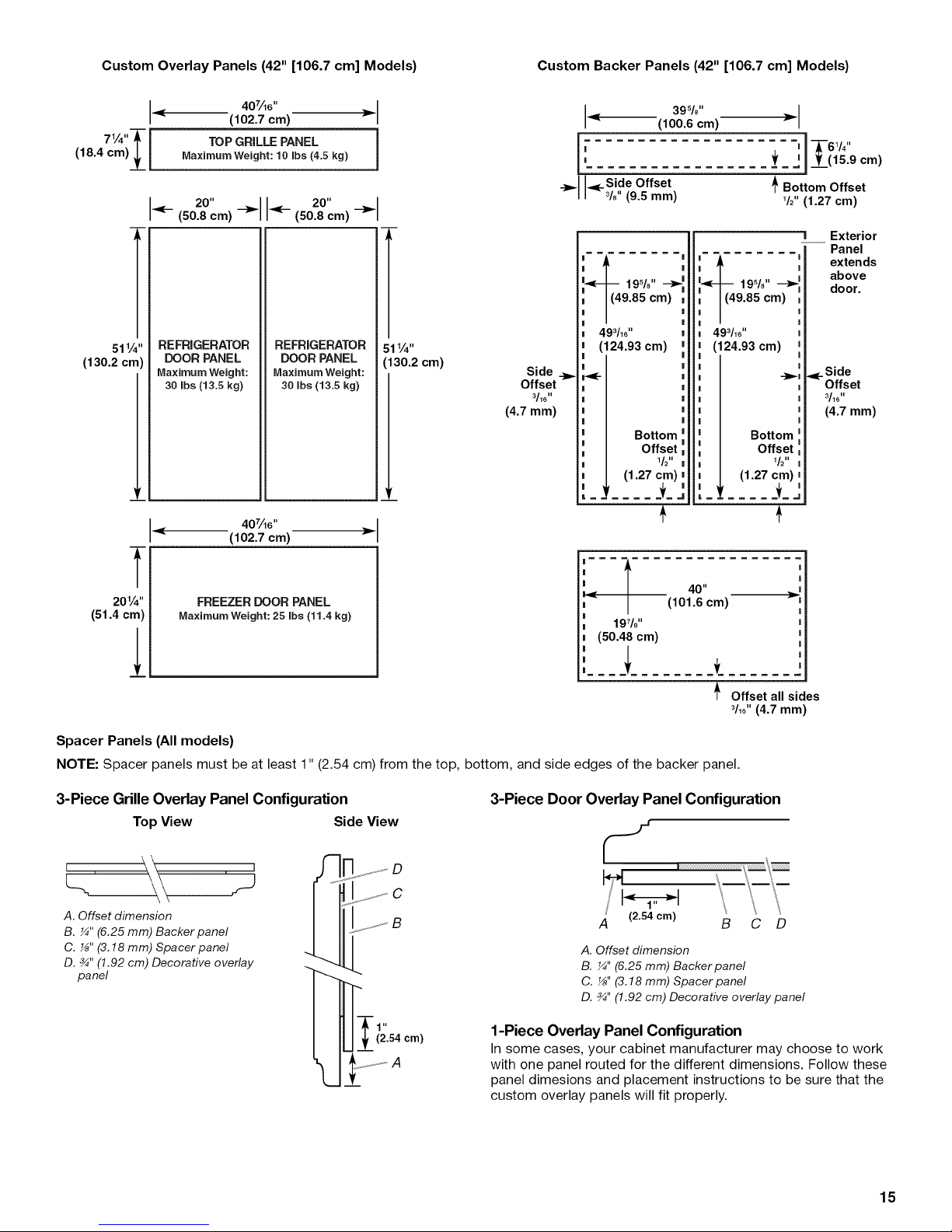
Custom Overlay Panels (42" [106.7 cm] Models) Custom Backer Panels (42" [106.7 cm] Models)
407A6''
(102.7 cm)
71/4"T i TOP GRILLE PANEL i
(18.4 cm)__l Maximum Weight:10 robs(4.5 kg)
(50.2-0"m)8c-_ <(-- 20" __.
(50.8 cm)
T
511/4"
(130.2 cm)
REFRIGERATOR
DOOR PANEL
MaximumWeight:
30 Ibs (13.5 kg)
REFRIGERATOR
DOOR PANEL
Maximum Weight:
30 robs(13.5 kg)
l
511/4"
(130.2 cm)
Side
Offset
3/16 II
(4.7 ram)
, ,IT61/ ,,
i -
' _f I1 ____(15.9cm)
_>_ __Side Offset /_Bottom Offset
3/8 (9.5 mm) 1/2"(1.27 cm)
493116''
(124.93 cm)
,K-
(1.27 cm)
(100.6 cm)
Bottom
Offset
1/211
39%"
493116''
(124.93 cm)
Bottom
Offset
1/211
(1.27 cm)
_i .... _L
! Exterior
Panel
extends
above
door.
.<_Side
Offset
3/16 II
(4.7 mm)
4077_6''
(102.7 em)
T
201/4"
(51.4 cm)
Spacer Panels (All models)
NOTE: Spacer panels must be at least 1" (2.54 cm) from the top, bottom, and side edges of the backer panel.
3-Piece Grille Overlay Panel Configuration
TopView Side View
FREEZER DOOR PANEL
Maximum Weight: 25 Ibs (11.4 kg)
3-Piece Door Overlay Panel Configuration
I
|||== = =l
=.
i 19!/| ii
II 8
I (50.48 cm)
I
| .........
f
40"
(101.6 cm)
_- Offset all sides
S
A. Offset dimension
B. ¼" (6.25 mm) Backer panel
C. _" (3.18 mm) Spacer panel
D. _" (1.92 cm) Decorative overlay
panel
ii i!
.............. S
_,f, S'_ D
A. Offset dimension
B. ¼" (6.25 mm) Backer panel
C. _" (3.18 mm) Spacer panel
D. _" (1.92 cm) Decorative overlay panel
3/16"(4.7 mm)
C D
..... A
1-Piece Overlay Panel Configuration
In some cases, your cabinet manufacturer may choose to work
with one panel routed for the different dimensions. Follow these
panel dimesions and placement instructions to be sure that the
custom overlay panels will fit properly.
15
Page 16
l<a<tO[W I I ilell lid " =°=
All factory parts are available through your KitchenAid dealer or
by calling KitchenAid Parts and Accessories at 1-800-442-9991
In Canada, call 1-800-807-6777.
A 72" (183 cm) wide Top Grille Panel Kit is available. This kit
allows 2 units (one left-hand swing and one right-hand) to be
installed side by side with a single grille.
,/ ....... _3 I2 / t = ])F' ..... .................
Architecf Series 72" (183 cm) Top Grille Panel Kit
J
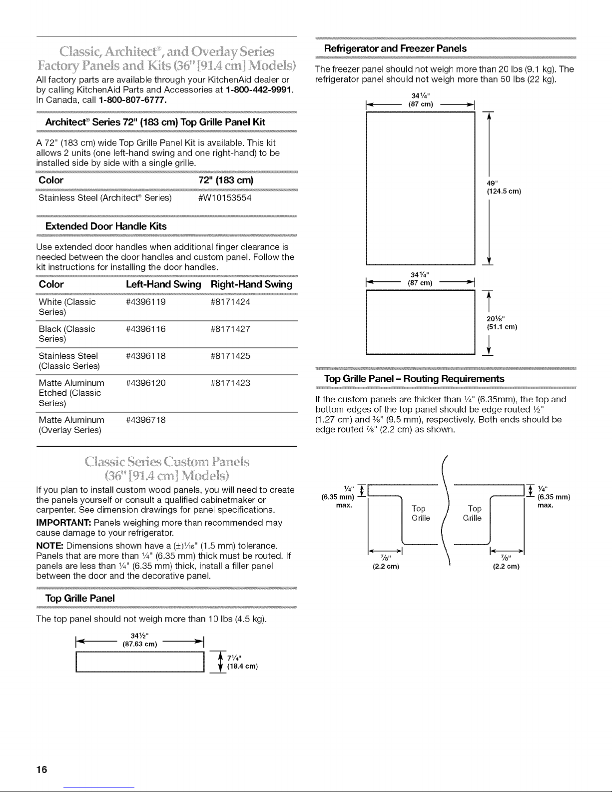
Refrigerator and Freezer Panels
The freezer panel should not weigh more than 20 Ibs (9.1 kg). The
refrigerator panel should not weigh more than 50 Ibs (22 kg).
341/4"
(87 cm)
Color 72" (183 cm)
Stainless Steel (Architect _Series) #W10153554
Extended Door Handle Kits
Use extended door handles when additional finger clearance is
needed between the door handles and custom panel. Follow the
kit instructions for installing the door handles.
Color Left-Hand Swing Right-Hand Swing
White (Classic #4396119 #8171424
Series)
Black (Classic #4396116 #8171427
Series)
Stainless Steel #4396118 #8171425
(Classic Series)
Matte Aluminum #4396120 #8171423
Etched (Classic
Series)
Matte Aluminum #4396718
(Overlay Series)
49"
(124.5 cm)
341/4"
"_ (87 cm)
Y
201/8"
(61.1 cm)
]
Top Grille Panel - Routing Requirements
If the custom panels are thicker than V4"(6.35mm), the top and
bottom edges of the top panel should be edge routed V2"
(1.27 cm) and 3/8"(9.5 mm), respectively. Both ends should be
edge routed 7/8"(2.2 cm) as shown.
loi l)d. d,d>l
If you plan to install custom wood panels, you will need to create
the panels yourself or consult a qualified cabinetmaker or
carpenter. See dimension drawings for panel specifications.
IMPORTANT: Panels weighing more than recommended may
cause damage to your refrigerator.
NOTE: Dimensions shown have a (+)He" (1.5 mm) tolerance.
Panels that are more than V4"(6.35 mm) thick must be routed. If
panels are less than V4"(6.35 mm) thick, install a filler panel
between the door and the decorative panel.
Top Grille Panel
The top panel should not weigh more than 10 Ibs (4.5 kg).
I_ 341/2"
(87.63 cm) _ I
_lt (18.4 cm)
(6.35 mm) -- _] Grile
max. L._T°P
(2.2 cm)
Grille
Top J max.
(2.2 cm)
Y4''
(6.35 mm)
16
Page 17
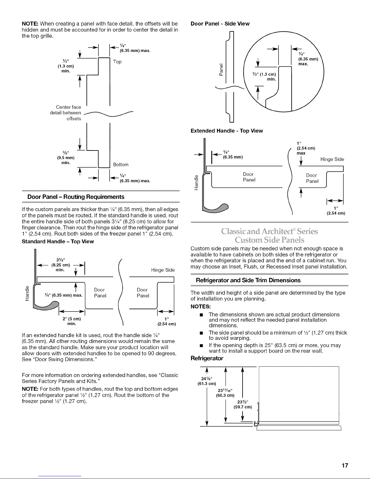
NOTE: When creating a panel with face detail, the offsets will be
hidden and must be accounted for in order to center the detail in
the top grille.
.,_ 1,/4"
(6.36 mm) max.
V2" Top
(1.3 cm)
Center face
detail between _
(9.5mm)
--l-
rnin.
offsets
%" 1
min. Bottom
Door Panel - Side View
J--
Q_
Extended Handle - Top View
I _ 1/4"
(6.35 mm)
1 "
(2.64 cm)
mix Hinge Side
___ _:-- _4:35 ram) max.
Door Panel - Routing Requirements
If the custom panels are thicker than 1/4"(6.35 mm), then all edges
of the panels must be routed. If the standard handle is used, rout
the entire handle side of both panels 31/4'' (8.25 cm) to allow for
finger clearance. Then rout the hinge side of the refrigerator panel
1" (2.54 cm). Rout both sides of the freezer panel 1" (2.54 cm).
Standard Handle - Top View
31/4 ''
_-_ (8.25 cm)
O_
= t
_3
"1-
If an extended handle kit is used, rout the handle side 1/4"
(6.35 mm). All other routing dimensions would remain the same
as the standard handle. Make sure your product location will
allow doors with extended handles to be opened to 90 degrees.
See "Door Swing Dimensions."
mln.
1/4" (6.35 mm) max. /
2" (5 cm)
min.
1
/
Door
Panel
Hinge Side
Door I _]
] "
(2.54 cm)
(1)
_] Door
c
o5
q-
Custom side panels may be needed when not enough space is
available to have cabinets on both sides of the refrigerator or
when the refrigerator is placed and the end of a cabinet run. You
may choose an Inset, Flush, or Recessed Inset panel installation.
Refrigerator and Side Trim Dimensions
The width and height of a side panel are determined by the type
of installation you are planning.
NOTES:
• The dimensions shown are actual product dimensions
and may not reflect the needed panel installation
dimensions.
• The side panel should be a minimum of 1/2"(1.27 cm) thick
to avoid warping.
• If the opening depth is 25" (63.5 cm) or more, you may
want to install a support board on the rear wall.
Panel
Door r_
1 "
(2.54 cm)
Refrigerator
For more information on ordering extended handles, see "Classic
Series Factory Panels and Kits."
NOTE: For both types of handles, rout the top and bottom edges
of the refrigerator panel 1/2"(1.27 cm). Rout the bottom of the
freezer panel 1/2"(1.27 cm).
241/8"
(61.3 cm)
'TT
(60.3 cm)
231/2,,
(59.7 cm)
23'1/16" f
17
Page 18
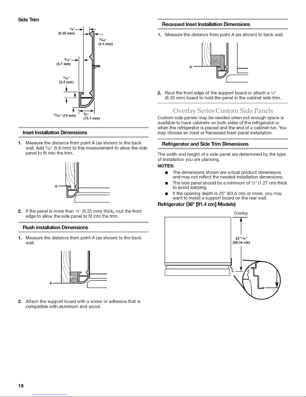
Side Trim
Recessed Inset Installation Dimensions
(6.35 mm)
11/64"
(4.5 mm)
1%2" (10 mm) v/8
(15.7 mm)
Inset Installation Dimensions
1. Measure the distance from point A (as shown) to the back
wall. Add 7/32"(5.6 mm) to this measurement to allow the side
panel to fit into the trim.
2. If the panel is more than 1/4"(6.35 mm) thick, rout the front
edge to allow the side panel to fit into the trim.
1. Measure the distance from point A (asshown) to back wall.
2. Rout the front edge of the support board or attach a 1/4"
(6.35 mm) board to hold the panel in the cabinet side trim.
i'I I]iI_:,I
Custom side panels may be needed when not enough space is
available to have cabinets on both sides of the refrigerator or
when the refrigerator is placed and the end of a cabinet run. You
may choose an Inset or Recessed Inset panel installation.
Refrigerator and Side Trim Dimensions
The width and height of a side panel are determined by the type
of installation you are planning.
NOTES:
• The dimensions shown are actual product dimensions
and may not reflect the needed installation dimensions.
• The side panel should be a minimum of 1/2"(1.27 cm) thick
to avoid warping.
• If the opening depth is 25" (63.5 cm) or more, you may
want to install a support board on the rear wall.
Refrigerator (36" [91.4 cm] Models)
Overlay
Flush Installation Dimensions
1. Measure the distance from point A (as shown) to the back
wall.
A
2. Attach the support board with a screw or adhesive that is
compatible with aluminum and wood.
2311/16''
(60.16 cm)
18
Page 19
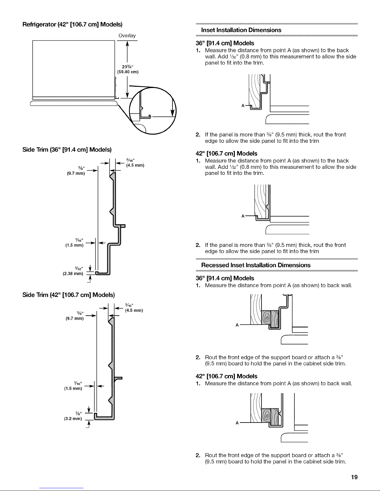
Refrigerator (42" [106.7 cm] Models)
(59.40 cm)
Side Trim (36" [91.4 cm] Models)
3'/8"
(9.7 mm)
Overlay
233/8''
Inset Installation Dimensions
36" [91.4 cm] Models
1. Measure the distance from point A (as shown) to the back
wall. Add 1/32"(0.8 mm) to this measurement to allow the side
panel to fit into the trim.
(-
2. If the panel is more than 3/8"(9.5 mm) thick, rout the front
edge to allow the side panel to fit into the trim
42" [106.7 cm] Models
1. Measure the distance from point A (as shown) to the back
wall. Add 1/32"(0.8 mm) to this measurement to allow the side
panel to fit into the trim.
1_611
(1.5 mm)
3/32"
(2.38 mm)
Side Trim (42" [106.7 cm] Models)
%. --_ L=_ 3/16''
(9.7 mm)
1,/16"
(1.5 mm)
(3.2 mm)
2. If the panel is more than 3/8"(9.5 mm) thick, rout the front
edge to allow the side panel to fit into the trim
Recessed Inset Installation Dimensions
36" [91.4 cm] Models
1. Measure the distance from point A (asshown) to back wall.
I_ (4.5 mm)
2. Rout the front edge of the support board or attach a 3/8"
(9.5 mm) board to hold the panel in the cabinet side trim.
42" [106.7 cm] Models
1. Measure the distance from point A (asshown) to back wall.
A m
2. Rout the front edge of the support board or attach a 3/8"
(9.5 mm) board to hold the panel in the cabinet side trim.
19
Page 20
INSTALLATION INSTRUCTIONS
_ l-_SO_d_<¸<_ _ _ _<,_.... _,o,,_........
Tip Over Hazard
Refrigerator is top heavy and tips easily when not
completely installed.
Keep doors taped closed until refrigerator is
completely installed.
Use two or more people to move and install
refrigerator.
Failure to do so can result in death or serious injury.
IMPORTANT:
• Do not remove the film covering until the refrigerator is in its
operating location.
• All four leveling legs must contact the floor to support and
stabilize the full weight of the refrigerator.
• Keep the cardboard shipping piece or plywood under the
refrigerator until it is installed in the operating location.
1. Remove and save the literature package bag taped to the
side of the refrigerator and the parts bag behind the grille.
Remove the four brackets (two on each side) that attach the
shipping base to the refrigerator bottom.
NOTE: Do not remove tape and door bracing until the
refrigerator is in its final location.
2. If necessary, reduce the tipping radius. See "Tipping Radius"
for ceiling height requirements or "Reduce Tipping Radius"
for step-by-step instructions. Ifyou do not need to reduce the
tipping radius, proceed to "Move the Refrigerator into
House."
Before bringing the refrigerator into the home, be sure there is
adequate ceiling height to stand the refrigerator upright. See
"Tipping Radius" in the "Installation Requirements" section for
more information.
If you do not have adequate ceiling height to stand the
refrigerator upright, the tipping radius can be reduced by
removing the top grille and side trims (see the following chart).
Model Reduced Tipping Radius
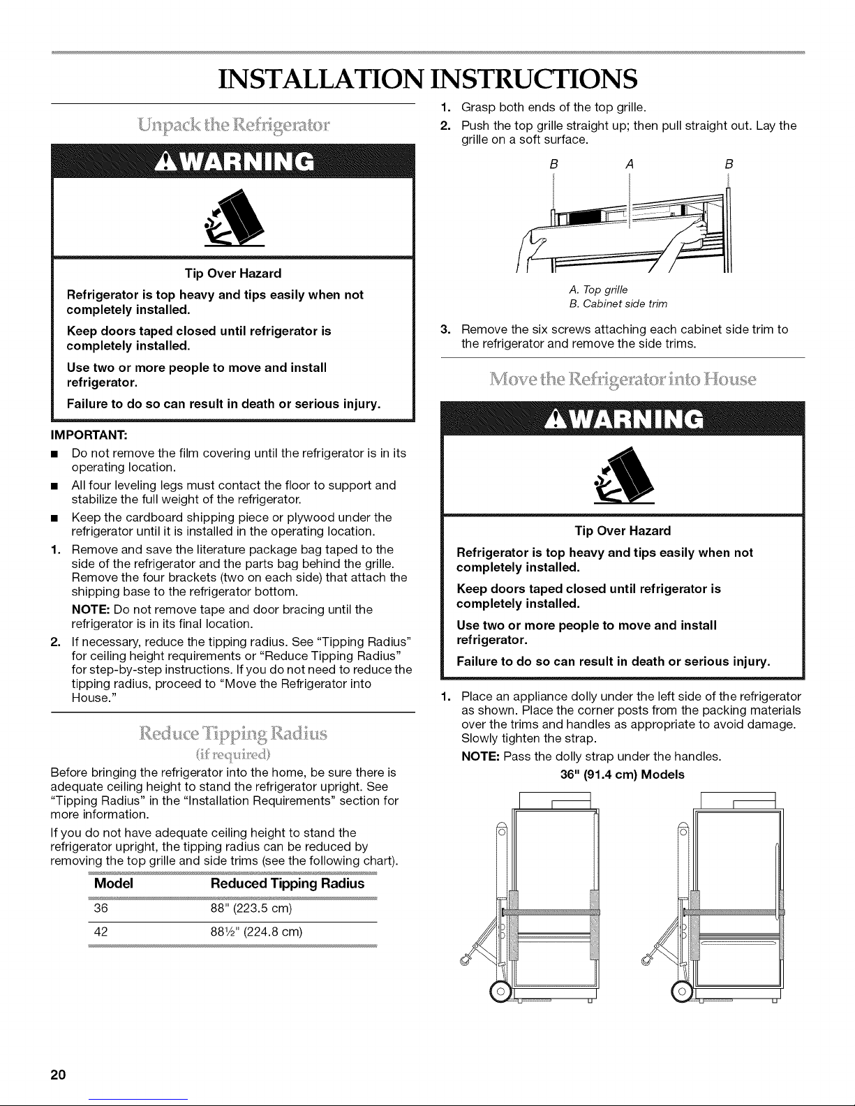
1. Grasp both ends of the top grille.
2. Push the top grille straight up; then pull straight out. Lay the
grille on a soft surface.
B
A. Top grille
B. Cabinet side trim
3.
Remove the six screws attaching each cabinet side trim to
the refrigerator and remove the side trims.
Tip Over Hazard
Refrigerator is top heavy and tips easily when not
completely installed.
Keep doors taped closed until refrigerator is
completely installed.
Use two or more people to move and install
refrigerator.
Failure to do so can result in death or serious injury.
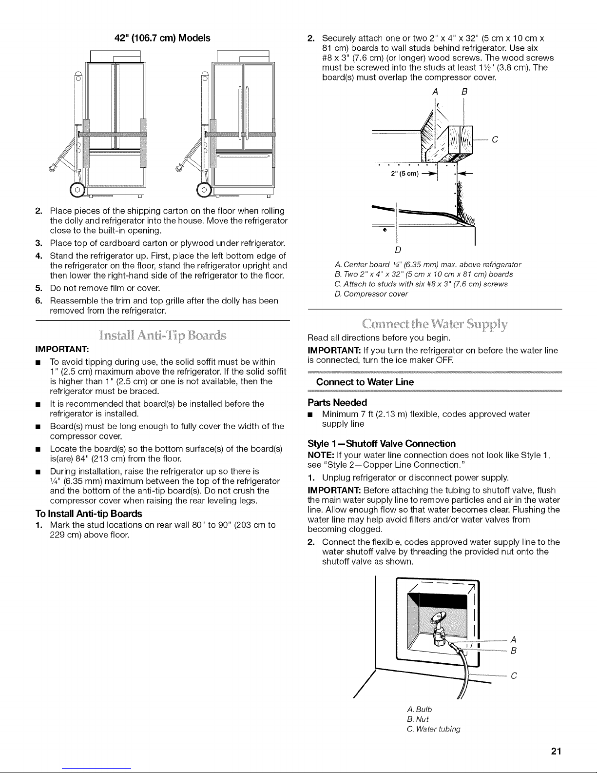
1.
Place an appliance dolly under the left side of the refrigerator
as shown. Place the corner posts from the packing materials
over the trims and handles as appropriate to avoid damage.
Slowly tighten the strap.
NOTE: Pass the dolly strap under the handles.
36" (91.4 cm) Models
36 88" (223.5 cm)
42 881/2"(224.8 cm)
20
Page 21
42" (106.7 cm) Models
2. Place pieces of the shipping carton on the floor when rolling
the dolly and refrigerator into the house. Move the refrigerator
close to the built-in opening.
3. Place top of cardboard carton or plywood under refrigerator.
4. Stand the refrigerator up. First, place the left bottom edge of
the refrigerator on the floor, stand the refrigerator upright and
then lower the right-hand side of the refrigerator to the floor.
5. Do not remove film or cover.
6. Reassemble the trim and top grille after the dolly has been
removed from the refrigerator.
2.
Securely attach one or two 2" x 4" x 32" (5 cm x 10 cm x
81 cm) boards to wall studs behind refrigerator. Use six
#8 x 3" (7.6 cm) (or longer) wood screws. The wood screws
must be screwed into the studs at least 11/2"(3.8 cm). The
board(s) must overlap the compressor cover.
A B
C
2" (5 cm)
D
A. Center board _" (6.35 mm) max. above refrigerator
B. Two 2" x 4" x 32" (5 cm x 10 cm x 81 cm) boards
C.Attach to studs with six #8 x 3" (7.6 cm) screws
D. Compressor cover
IMPORTANT:
• To avoid tipping during use, the solid soffit must be within
1" (2.5 cm) maximum above the refrigerator. If the solid soffit
is higher than 1" (2.5 cm) or one is not available, then the
refrigerator must be braced.
• It is recommended that board(s) be installed before the
refrigerator is installed.
• Board(s) must be long enough to fully cover the width of the
compressor cover.
• Locate the board(s) so the bottom surface(s) of the board(s)
is(are) 84" (213 cm) from the floor.
• During installation, raise the refrigerator up so there is
V4"(6.35 mm) maximum between the top of the refrigerator
and the bottom of the anti-tip board(s). Do not crush the
compressor cover when raising the rear leveling legs.
To Install Anti-tip Boards
1. Mark the stud locations on rear wall 80" to 90" (203 cm to
229 cm) above floor.
Read all directions before you begin.
IMPORTANT: If you turn the refrigerator on before the water line
is connected, turn the ice maker OFE
Connect to Water Line
Parts Needed
• Minimum 7 ft (2.13 m) flexible, codes approved water
supply line
Style 1 --Shutoff Valve Connection
NOTE: If your water line connection does not look like Style 1,
see "Style 2--Copper Line Connection."
1. Unplug refrigerator or disconnect power supply.
IMPORTANT: Before attaching the tubing to shutoff valve, flush
the main water supply line to remove particles and air in the water
line. Allow enough flow so that water becomes clear. Flushing the
water line may help avoid filters and/or water valves from
becoming clogged.
2. Connect the flexible, codes approved water supply line to the
water shutoff valve by threading the provided nut onto the
shutoff valve as shown.
A. Bulb
B. Nut
C. Water tubing
II I
A
B
C
21
Page 22
3. Place the end of the tubing into a bucket, and turn shutoff
valve ON.
4. Check for leaks. Tighten any nuts or connections (including
connections at the valve) that leak.
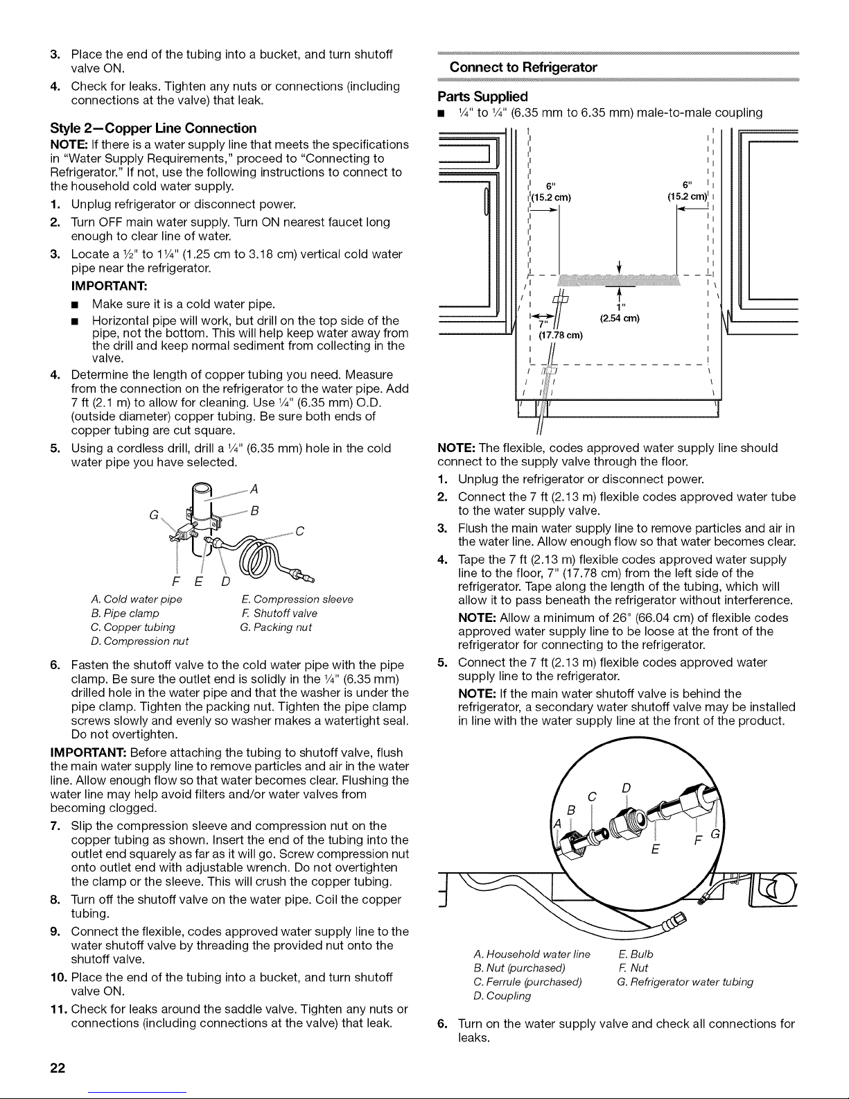
Style 2--Copper Line Connection
NOTE: If there is a water supply line that meets the specifications
in "Water Supply Requirements," proceed to "Connecting to
Refrigerator." If not, use the following instructions to connect to
the household cold water supply.
1. Unplug refrigerator or disconnect power.
2. Turn OFF main water supply. Turn ON nearest faucet long
enough to clear line of water.
3. Locate a 1/2"to 1V4" (1.25 cm to 3.18 cm) vertical cold water
pipe near the refrigerator.
IMPORTANT:
• Make sure it is a cold water pipe.
• Horizontal pipe will work, but drill on the top side of the
pipe, not the bottom. This will help keep water away from
the drill and keep normal sediment from collecting in the
valve.
4. Determine the length of copper tubing you need. Measure
from the connection on the refrigerator to the water pipe. Add
7 ft (2.1 m) to allow for cleaning. Use 1/4"(6.35 mm) O.D.
(outside diameter) copper tubing. Be sure both ends of
copper tubing are cut square.
5. Using a cordless drill, drill a 1/4"(6.35 mm) hole in the cold
water pipe you have selected.
A. Cold waterpipe E.Compressionsleeve
B.Pipe clamp F Shutoff valve
C. Copper tubing G.Packing nut
D. Compression nut
6. Fasten the shutoff valve to the cold water pipe with the pipe
clamp. Be sure the outlet end is solidly in the 1/4"(6.35 mm)
drilled hole in the water pipe and that the washer is under the
pipe clamp. Tighten the packing nut. Tighten the pipe clamp
screws slowly and evenly so washer makes a watertight seal.
Do not overtighten.
IMPORTANT: Before attaching the tubing to shutoff valve, flush
the main water supply line to remove particles and air in the water
line. Allow enough flow so that water becomes clear. Flushing the
water line may help avoid filters and/or water valves from
becoming clogged.
7. Slip the compression sleeve and compression nut on the
copper tubing as shown. Insert the end of the tubing into the
outlet end squarely as far as it will go. Screw compression nut
onto outlet end with adjustable wrench. Do not overtighten
the clamp or the sleeve. This will crush the copper tubing.
8. Turn off the shutoff valve on the water pipe. Coil the copper
tubing.
9. Connect the flexible, codes approved water supply line to the
water shutoff valve by threading the provided nut onto the
shutoff valve.
10. Place the end of the tubing into a bucket, and turn shutoff
valve ON.
11. Check for leaks around the saddle valve. Tighten any nuts or
connections (including connections at the valve) that leak.
Connect to Refrigerator
Parts Supplied
• 1/4"to 1/4"(6.35mm to 6.35 mm) male-to-male coupling
{I
{I
6 II
1 ii
(2.54 cm)
I (17.78 cm)
NOTE: The flexible, codes approved water supply line should
connect to the supply valve through the floor.
1. Unplug the refrigerator or disconnect power.
2. Connect the 7 ft (2.13 m) flexible codes approved water tube
to the water supply valve.
3. Flush the main water supply line to remove particles and air in
the water line. Allow enough flow so that water becomes clear.
4. Tape the 7 ft (2.13 m) flexible codes approved water supply
line to the floor, 7" (17.78 cm) from the left side of the
refrigerator. Tape along the length of the tubing, which will
allow it to pass beneath the refrigerator without interference.
NOTE: Allow a minimum of 26" (66.04 cm) of flexible codes
approved water supply line to be loose at the front of the
refrigerator for connecting to the refrigerator.
5. Connect the 7 ft (2.13 m) flexible codes approved water
supply line to the refrigerator.
NOTE: If the main water shutoff valve is behind the
refrigerator, a secondary water shutoff valve may be installed
in line with the water supply line at the front of the 3roduct.
A. Household water line E. Bulb
B. Nut (purchased) F Nut
C. Ferrule (purchased) G. Refrigerator water tubing
D. Coupfing
6. Turn on the water supply valve and check all connections for
leaks.
6 II
(15.2 cm)lI
22
Page 23
8
Electrical Shock Hazard
Plug into a grounded 3 prong outlet.
Do not remove ground prong.
Do not use an adapter.
Do not use an extension cord.
Failure to follow these instructions can result in death,
fire, or electrical shock.
1. Set control switch at top of cabinet to the OFF position.
2. Plug into a grounded 3 prong outlet.
Tip Over Hazard
Refrigerator is top heavy and tips easily when not
completely installed.
Keep doors taped closed until refrigerator is
completely installed.
Use two or more people to move and install
refrigerator.
Failure to do so can result in death or serious injury.
Tip Over Hazard
Refrigerator is top heavy and tips easily when not
completely installed.
Keep doors taped closed until refrigerator is
completely installed.
Use two or more people to move and install
refrigerator.
Failure to do so can result in death or serious injury.
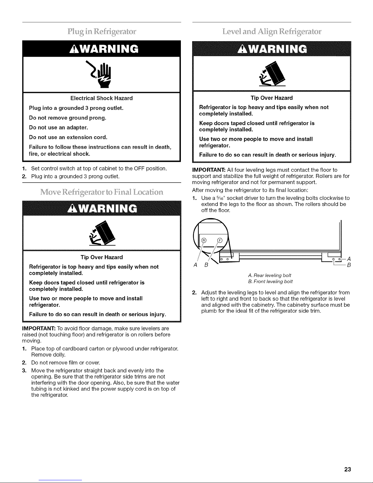
IMPORTANT: All four leveling legs must contact the floor to
support and stabilize the full weight of refrigerator. Rollers are for
moving refrigerator and not for permanent support.
After moving the refrigerator to its final location:
1. Use a %e" socket driver to turn the leveling bolts clockwise to
extend the legs to the floor as shown. The rollers should be
off the floor.
S
A. Rear leveling bolt
B. Front leveling bolt
2.
Adjust the leveling legs to level and align the refrigerator from
left to right and front to back so that the refrigerator is level
and aligned with the cabinetry. The cabinetry surface must be
plumb for the ideal fit of the refrigerator side trim.
IMPORTANT: To avoid floor damage, make sure levelers are
raised (not touching floor) and refrigerator is on rollers before
moving.
1. Place top of cardboard carton or plywood under refrigerator.
Remove dolly.
2. Do not remove film or cover.
3. Move the refrigerator straight back and evenly into the
opening. Be sure that the refrigerator side trims are not
interfering with the door opening. Also, be sure that the water
tubing is not kinked and the power supply cord is on top of
the refrigerator.
23
Page 24
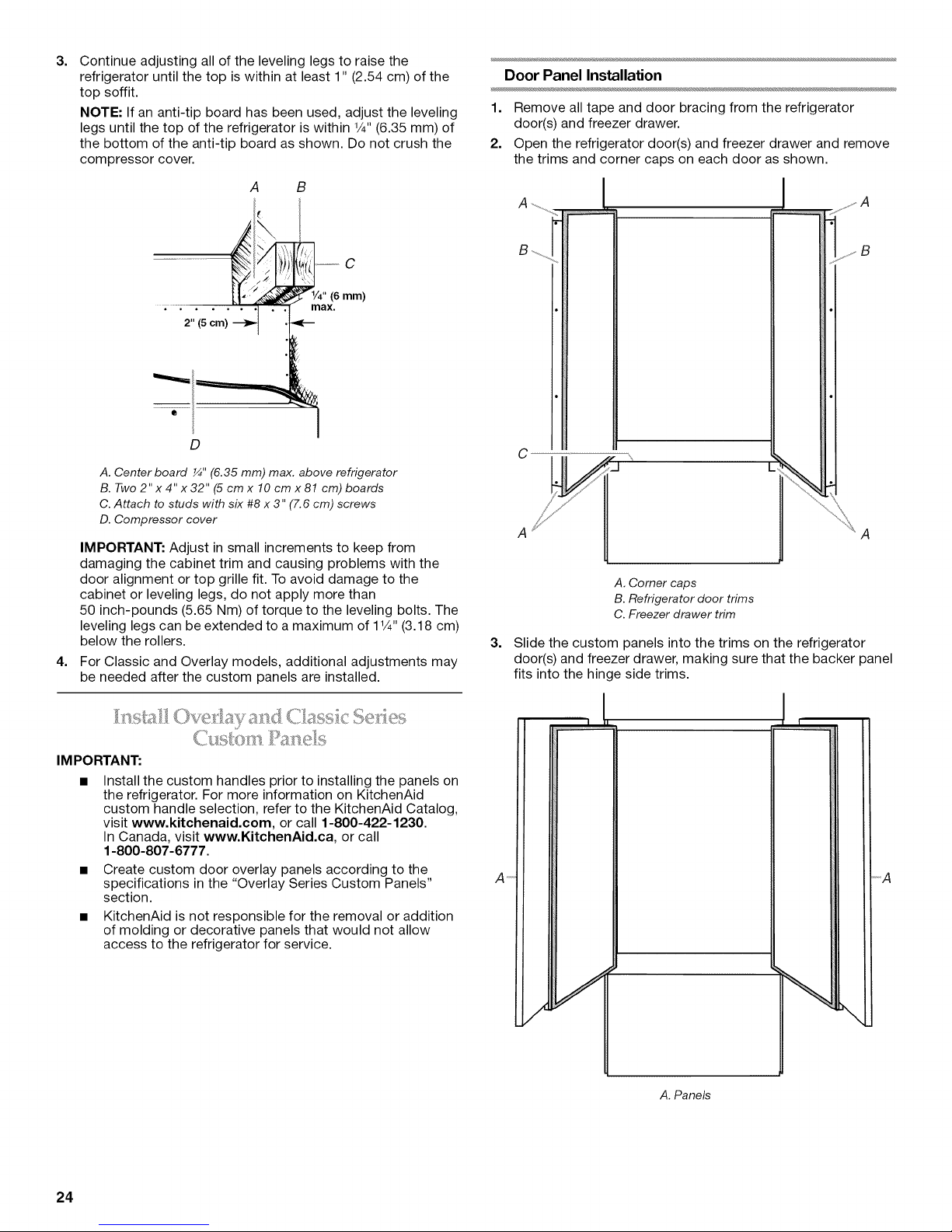
3.
Continue adjusting all of the leveling legs to raise the
refrigerator until the top is within at least 1" (2.54 cm) of the
top soffit.
NOTE: If an anti-tip board has been used, adjust the leveling
legs until the top of the refrigerator is within 1/4"(6.35 mm) of
the bottom of the anti-tip board as shown. Do not crush the
compressor cover.
A
B
)
l
" (6 mm)
max.
2" (5 cm) _ •
Door Panel Installation
1. Remove all tape and door bracing from the refrigerator
door(s) and freezer drawer.
2. Open the refrigerator door(s) and freezer drawer and remove
the trims and corner caps on each door as shown.
......_ A
D
A. Center board ¼" (6.35 mm) max. above refrigerator
B. Two 2" x 4" x 32" (5 cm x 10 cm x 81 cm) boards
C.Attach to studs with six #8 x 3" (7.6 cm) screws
D. Compressor cover
IMPORTANT: Adjust in small increments to keep from
damaging the cabinet trim and causing problems with the
door alignment or top grille fit. To avoid damage to the
cabinet or leveling legs, do not apply more than
50 inch-pounds (5.65 Nm) of torque to the leveling bolts. The
leveling legs can be extended to a maximum of 1V4"(3.18 cm)
below the rollers.
4.
For Classic and Overlay models, additional adjustments may
be needed after the custom panels are installed.
IMPORTANT:
Install the custom handles prior to installing the panels on
the refrigerator. For more information on KitchenAid
custom handle selection, refer to the KitchenAid Catalog,
visit www.kitchenaid.com, or call 1-800-422-1230.
In Canada, visit www.KitchenAid.ca, or call
1-800-807-6777.
• Create custom door overlay panels according to the
specifications in the "Overlay Series Custom Panels"
section.
• KitchenAid is not responsible for the removal or addition
of molding or decorative panels that would not allow
access to the refrigerator for service.
C
A
A. Corner caps
B. Refrigerator door trims
C. Freezer drawer trim
3.
Slide the custom panels into the trims on the refrigerator
door(s) and freezer drawer, making sure that the backer panel
fits into the hinge side trims.
A'_
_A
--A
24
A. Pane_
Page 25

4. Reinstall the trims and corner caps.
5. Remove the film from the screw covers. Snap the screw
covers into the handle trim section.
Top Grille Panel
5.
Replace the top grille in the cabinet side trims and pull the
panel down slightly to lock it into place.
B
A. Top grille
B. Cabinet side trims
1. Grasp both ends of the top grille.
2. Push straight up; then pull straight out. Place the top grille
panel-side down on a soft working surface.
B A B
A. Top grille
B. Cabinet side trims
3.
Remove one end cap by loosening the nuts and sliding the
end cap off.
A
c
A.Bottom rail C.End cap
B.Nuts D. Toprail
4.
Slide the custom panel into the top grille channel and
reattach the end cap.
Door Alignment (36" [91.4 cm] Models)
1. Loosen, but do not remove, the four Torx®t27 flat-head
mounting screws and the two 1/4"hex-head mounting screws
in the top hinge.
2. Adjust the top hinge of the door to align it.
3. Tighten the Torx®t27 flat-head mounting screws to a torque
of approximately 100 inch-pounds (11.3 Nm).
4. Tighten the 1/4"hex-head screws.
A
A. Torx®*27 flat-head mounting screws
B. _" hex-head mounting screws
Door Height Adjustment (42" [106.7 cm] Models)
Use the following steps to adjust the door height, up or down,
after the refrigerator has been leveled.
NOTE: Adjust the right door to the position of the left door first. If
it is necessary to adjust the left door, you must make sure that the
hinged center rail located on the left-hand door does not drag
when closing the door.
1. Open the freezer drawer. Remove the locking plate screw
from the bottom side of the refrigerator door hinge using a
1/4"open-end wrench.
A
A. Custom panel
A B C
A. Bushing
B. Locking plate
C. Locking plate screw
25
Page 26

2.
Remove the locking plate as shown.
3. Turn the bushing located underneath the bottom of the hinge
using a 1/2"open-end wrench. Turning the bushing to the left
will lower the door. Turning the bushing right will raise the
door.
4. After adjusting, check the doors to make sure they are even
at the top and bottom. If the doors are not even, continue to
turn the bushing to adjust the door.
5. Replace the locking plate.
• Turn the bushing slightly to align the hinge and locking
plate screw holes.
• Replace and tighten the locking plate screw.
6. Make final check to make sure the doors are aligned and
even.
Door Swing Adjustment
36" (91.4 cm) Models
1. Check that the refrigerator door can open freely. If the door
opens too wide, remove the door stop screw from the bottom
hinge with a Torx_tT15 screwdriver.
3.
Replace the door stop screw in the bottom hinge and tighten.
IMPORTANT: Do not place the door stop screw in the 130 °
position on Overlay Series models. See "Handle and Door
Clearances."
!
A B c
A. 130 °
B. 110 ° (Overlay series)
C. 90 °
42" (106.7 cm) Models
1. Check that the refrigerator door can open freely. If the door
opens too wide, you will have to adjust the door stop
position.
2. Grasp both ends of the top grille.
3. Push the top grille straight up, then pull straight out. Lay the
grille on a soft surface.
B
A. Door stop screw
2.
Hold the door open to a position that is less than 90°.
A. Top grille
B. Cabinet side trims
4.
The door stop is located on the top hinge.
A
\\
B-
A. Door stop screw ",4"
B. Door stop screw "B"
C. Door stop
C
1-®TORX is a registered trademark of Saturn Fasteners, Inc.
26
Page 27

5.
Remove the 2 door stop screws.
• To remove the outer screw ("A"):
With the door closed, firmly press the L-shaped bracket
toward the center of the refrigerator until the screw is
exposed.
• To remove the inner screw ("B"):
Open the door 90° and the L-shaped bracket will expose
the screw.
@
A. Door stop screw "A"
B. Door stop screw "B"
6. Reverse or rotate the door stop to the desired position as
shown below.
NOTE: For Overlay Series models, rout the hinge side of the
custom door panels to a radius that is equal to at least half the
thickness of the panel if a 130° door swing is desired.
If the built-in area depth is 25" (63.5 cm) or more, the side panels
can be installed inside the side trim or attached to the outside of
the side trim.
IMPORTANT: KitchenAid is not responsible for the removal or
addition of molding or decorative panels that would not allow
access to the refrigerator for service.
1. For the inside side trim piece, slide the front edge of the
routed side panel into the trim piece.
2. Nail the rear edge of the panel to the support board.
A
J
130° 110°
,._..J j
90 ° 90 °
Left-hand as shown; Right-hand reversed
7. Replace the door stop screws and tighten.
8. Check that the door can open freely.
.¢¢:)
A. Support board
B. Side trim piece
@
27
Page 28

There are two pieces to the base grille to allow for a custom fit:
the base grille itself and the skirt. The skirt can be added to the
base grille in order to extend it all the way to the floor.
1. To see whether the skirt is needed, place the base grille into
position. Do not attach the base grille to the refrigerator.
Measure the distance between the bottom of the base grille
and the floor. The gap must be a minimum of V2"(1.27 cm) in
order to add the skirt.
NOTE: If the gap measures less than V2"(1.27 cm), skip
steps 3 and 4 of the instructions, and install the base grille
only.
2. Remove the film from the base grille.
3. Snap the skirt onto the base grille.
}
A
B
1. Turn the water supply line valve to the "Open" position.
2. Turn the refrigerator switch to the ON position. See "Power
On/Off Switch" in the Use & Care Guide for instructions. Wait
a few minutes. Check the water line connections for leaks.
3. Remove all boxes, parts packages and packing materials
from the interior of the refrigerator. See the "Cleaning" section
in the Use & Care Guide for instructions. Remove the film and
cardboard from the grille and doors or door frame, depending
on your model.
4. Install the shelves and bins in the refrigerator and freezer
compartments.
5. The controls are preset at the factory to the midpoint setting.
Make sure the compressor is operating properly and that all
the lights are working.
6. If construction will continue after the refrigerator has been
installed, set the controls to OFR
To get the most efficient use from your new built-in refrigerator,
read the Use & Care Guide. Keep Installation Instructions and
Use & Care Guide near the built-in refrigerator for easy reference.
A. Base grille
B. Skirt
4,
Trim the skirt by scoring the proper "V" groove with a utility
knife. Break the skirt at the score line.
A
A. "V" groove
5,
Using the two screws, attach the base grille assembly to the
refrigerator as shown.
NOTE: Drive in the right side screw first.
A
A. Screws (2)
28
Page 29

SEGURIDAD DEL REFRIGERADOR
Su seguridad y la seguridad de los demos es muy importante.
Hemos incluido muchos mensajes importantes de seguridad en este manual yen su electrodomestico. Lea y obedezca siempre
todos los mensajes de seguridad.
Este es el simbolo de advertencia de seguridad.
Este simbolo le llama la atenci6n sobre peligros potenciales que pueden ocasionar la muerte o una lesi6n a
usted y a los demas.
Todos los mensajes de seguridad iran a continuaci6n del simbolo de advertencia de seguridad y de la palabra
"PELIGRO" o "ADVERTENCIA". Estas palabras significan:
Si no sigue las instrucciones de inmediato, usted puede
morir o sufrir una lesibn grave.
Si no sigue las instrucciones, usted puede morir o sufrir
una lesibn grave.
Todos los mensajes de seguridad le diran el peligro potencial, le diran c6mo reducir las posibilidades de sufrir una lesi6n y Io que
puede suceder si no se siguen las instrucciones.
Peligro de Vuelco
El refrigerador puede volcarse cuando est_ siendo
instalado debido a que la parte superior es pesada.
Mantenga las puertas cerradas con cinta hasta que el
refrigerador est_ completamente instaladoo
Use dos o m_s personas para mover e instalar el
refrigerador.
No seguir estas instrucciones puede ocasionar
la muerte o herida seria.
29
Page 30

MODELOS
_2
Serie Architect ° 'modelos de 36" [91,4 cm])
Presenta un estilo envolvente que complementa los contornos
de las manijas de la puerta. Esta serie ofrece un estilo
comercial calido para refrigeradores empotrados.
KBRC36FTS KBLC36FTS
Serie Classic (modelos de 36" [91,4 cm])
Presenta un adorno tipo tradicional instalado de fabrica que ofrece
un estilo "enmarcado". Esta serie requiere la instalacion de paneles
a la medida que no estfin incluidos.
KBRS36N-B KBRS36N-X KBLS36N-B KBLS36N-X
i
Serie de paneles recubiertos (modelos de 36" [91,4 cm])
Presenta un adorno recubierto instalado de fabrica que ofrece
un estilo "sin marco". Esta serie requiere la instalacion
de paneles, manijas y pedestales a la medida.
KBRO36FTX KBLO36FTX
3O
Serie Architect _ (modelos de 42" [106,7 cm])
Presenta un estilo envolvente que complementa los contornos de
las manijas de la puerta. Esta serie ofrece un estilo comercial calido
para refrigeradores empotrados.
KBFC42FTS
Page 31

Serie de paneles recubiertos (modelos de 42" [106,7 cm])
Presenta un adorno recubierto instalado de fabrica que ofrece
un estilo "sin marco". Esta serie requiere la instalacion de
paneles, manijas y pedestales a la medida.
KBFO42FTX
REQUISITOSDE
INSTALACION
• 1 6 2 tableros de madera de 2" x 4" x 32" (5 cm x 10 cm x
81 cm)
• Solicite los paneles de fabrica, hagalos a la medida o
consulte con un carpintero o fabricante de armarios
calificado para fabricar los paneles.
Serie Classic: Solicite los paneles de fabrica, hagalos a la
medida o consulte con un carpintero o fabricante de armarios
calificado para fabricar los paneles. Para obtener m_s
informacion, vea "Requisitos de instalacion".
Serie de paneles recubiertos: Haga los paneles a la medida o
consulte con un carpintero o fabricante de armarios
calificado para fabricarlos. Para obtener m_s informacion,
vea "Requisitos de instalacion".
La serie Architect ®se envia completa.
• Si esta conectando la linea de agua directamente a una
tuberia de cobre y no a una valvula de cierre, necesitarA una
ferula, una union y un accesorio de compresion de 1¼,,.
El refrigerador puede instalarse en un recinto entre los armarios o
al extremo de una linea de armarios utilizando un panel lateral
para cercar el refrigerador.
Peligro de Explosi6n
Mantenga los materiales y vapores inflamables,
tales como gasolina, alejados del refrigerador.
No seguir esta instrucci6n puede ocasionar la muerte,
explosi6n, o ineendio.
IMPORTANTE:
• Instalador: Deje las Instrucciones de instalacion con el
propietario.
• Propietario: Conserve las Instrucciones de instalacion para
referencia futura. Guarde estas Instrucciones de instalacion
para tenerlas a disposicion del inspector de electricidad
local.
Herramientas necesarias
Ensamble las herramientas y piezas necesarias antes de
comenzar la instalacion. Lea y siga las instrucciones provistas
con cualquiera de las herramientas enlistadas aqui.
• Taladro inalambrico
• Brocas
• Dos Ilaves ajustables
• Destornillador Phillips
• Nivel peque_o
• Plataforma rodante
para electrodomesticos
Piezas necesarias
• 6 tornillos para madera #8 x 3" (7,6 cm) (pudieran necesitarse
tornillos m_s largos)
t®TORX es una marca registrada de Saturn Fasteners, Inc.
• Destornilladores Torx®tT15 y T27
• Llave para tuercas de 1V32"
• Llaves de boca de 3/8",1/4"y 1/2"
• Llave hexagonal de 5/32"
• Llaves de cubo de 1/4"y %e"
• Cinta para medir
• Cuchillo para uso general
IMPORTANTE:
• Observe todos los codigos y reglamentos aplicables.
• No se recomienda instalar el refrigerador cerca de un horno,
radiador u otra fuente de calor.
• No instale el refrigerador cerca de una ubicacion en la que la
temperatura puede bajar de los 55°F (13°C).
• El piso debe soportar el peso del refrigerador, mas de
600 Ibs (272 kg), los paneles de las puertas y el contenido del
refrigerador.
• La altura del techo deberA permitir un arco de vuelco lateral.
Vea "Arco de vuelco".
• La ubicacion debe permitir que la puerta abra totalmente.
Vea "Medidas de oscilacion de la puerta".
• La ubicacion debe permitir que se quite la rejilla superior.
Vea "Medidas de la abertura".
Medidas de la abertura
Para evitar la inclinacion durante el uso, el plafon solido
debera estar a 1" (2,5 cm) como maximo por encima del
refrigerador. Si el plafon solido esta a una altura de m_s de 1"
(2,5 cm) o no hay ninguno disponible, entonces el
refrigerador debera tener un soporte.
Si se necesitan los tableros antivuelco, se deben fijar a los
pies derechos de la pared posterior de 80" a 90" (203 a
229 cm) arriba del piso. Vea "Como instalar los tableros
antivuelco" para recibir m_s informacion.
31
Page 32

NOTA: Se debe mantener un espacio de 1/2"(1,3 cm) frente al
adorno lateral del refrigerador para que la rejilla superior
pueda ser retirada.
Un contacto de tres terminales con conexion a tierra debe ser
ubicado a no mas de 4" (10,2 cm) a la derecha de los
armarios laterales o del panel del extremo. Vea "Requisitos
electricos" para obtener informacion adicional.
El cierre del agua deberA estar Iocalizado en la base del
armario, a cualquier lado del refrigerador o en algOn otro
lugar de facil acceso. Si la valvula de cierre del agua no esta
en los armarios, la tuberia para la linea del agua puede Ilegar
a traves del piso o de la pared trasera. Vea "Requisitos del
suministro de agua" para obtener informacion adicional.
ii
Ancho A para
Ancho A recubiertos Medida B
serie de paneles
(comose (comose (comose
muestra muestra muestra
Modelo
36 351/2" a 353/4" 353/4"a 36" 4" (10,2 cm)
42 411/2" a 413/4" 413/4"a 42" 10" (25,4 cm)
NOTA: El piso que esta debajo del refrigerador deberA estar al
mismo nivel que la habitacion.
anteriormente) anteriormente) anteriormente)
(90,2 cm a (90,8 cm a
90,8 cm) 91,4 cm)
(105,4 cm a (106 cm a
106 cm) 106,7 cm)
0
0
831/2" (212,1 cm) min.
843/4'' (215 cm) m_ix.
a la base de un
_lafbn sblido
_- A
Ancho
(vea el cuadro siguiente)
t
1"
(2,54 cm)
24"
(60,96 cm) min.
77"
(196 cm)
Peligro de Choque El_ctrico
B
t
Conecte a un contacto de pared de conexi6n a tierra de
3 terminales.
No quite la terminal de conexi6n a tierra.
No use un adaptador.
No use un cable el_ctrico de extensi6n.
No seguir estas instrucciones puede ocasionar
la muerte, incendio o choque el6ctrico.
Antes de mover el refrigerador a su posicion definitiva, es
importante asegurarse que Ud. tiene la conexion electrica
adecuada.
M_todo de conexi6n a tierra recomendado
Se requiere una fuente de energia electrica de 115 Voltios,
60 Hz., CA solamente y con fusibles de 15 6 20 amp, conectada
a tierra. Se recomienda que se use un circuito separado solo
para su refrigerador. Use un tomacorriente que no se puede
apagar con un interruptor. No use un cable electrico de
extension.
IMPORTANTE: Si este producto esta conectado a un
tomacorriente protegido por un interruptor del circuito de falla
electrica de puesta a tierra (GFCI - Ground Fault Circuit
Interrupter), puede ocurrir un disparo brusco del suministro de
corriente, Io que resultarA en una perdida de enfriamiento. Esto
puede afectar la calidad y el sabor de los alimentos. Si ha
ocurrido un disparo brusco, y el alimento aparenta estar en malas
condiciones, deshagase del mismo.
NOTA: Antes de realizar cualquier tipo de instalacion, limpieza o
quitar un foco, quite la rejilla superior y ponga el interruptor
principal de energia en la posicion OFF (Apagado) o desconecte
el suministro de energia electrica en la caja de cortacircuitos.
Cuando haya terminado, ENCIENDA el interruptor principal de
energia o reconecte el suministro de energia en la caja de
cortacircuitos. Luego vuelva a ajustar el control en el ajuste
deseado.
32
Page 33

Todas las instalaciones deben hacerse de acuerdo a los
........... ]? _,,,<,
requerimientos locales de plomeria.
El cierre del agua deberA estar Iocalizado en el armario base,
a cualquier lado del refrigerador o en algOn otro lugar de facil
acceso. Se recomienda el lado derecho. El orificio de acceso
a traves del armario deberA estar a 1/2"(12,7 mm) de la pared
trasera como maximo.
NOTA" Si la valvula de cierre de agua esta en la pared
posterior detras del refrigerador, deberA haber un angulo de
manera que el tubo no se doble cuando se empuje el
refrigerador hacia su posicion final.
6"
(15,2 cm)
t
1"
(2,54 cm)
24"
(60,96 cm) min.
• Si la valvula de cierre del agua no esta en los armarios, la
tuberia para la linea del agua puede Ilegar a traves del piso.
Debera taladrarse un orificio de 1/2"(12,7 mm) para la
plomeria a por Io menos 6" (15,2 cm) del panel o armario del
lado derecho o izquierdo. En el piso, el orificio no debe estar
a mas de 1" (2,54 cm) de la pared trasera. Vea "Conecte el
suministro de agua".
• Si necesita tuberia adicional, use tuberias de cobre y revise si
hay fugas. Instale la tuberia de cobre solo en Areas donde la
temperatura vaya a permanecer por encima del punto de
congelacion.
• No use una valvula perforadora o una valvula de montura de
3_6" (4,76 mm) que reduce el flujo de agua y se obstruye con
mAs facilidad.
NOTA: El distribuidor de su refrigerador tiene disponible un
juego con una valvula de cierre tipo montura de 1/4"
(6,35 mm), una union y tuberia de cobre. Antes de comprar,
asegOrese que la valvula tipo montura cumpla con los
codigos de plomeria de su Iocalidad.
Presi6n del agua
Se necesita un suministro de agua fria con presion de agua entre
30 y 120 Ibs/pulg 2(207 y 827 kPa) para hacer funcionar el
despachador de agua y la fabrica de hielo. Si usted tiene
preguntas acerca de la presion de agua, Ilame a un plomero
competente autorizado.
Suministro de agua de 6smosis inversa
IMPORTANTE: La presion del suministro de agua que sale de un
sistema de osmosis inversa y va a la valvula de entrada de agua
del refrigerador necesitarA ser entre 30 y 120 Ibs/pulg 2 (207 y
827 kPa).
Si se conecta un sistema de filtracion de agua de osmosis
inversa al suministro de agua fria, la presion de agua al sistema
de osmosis inversa necesitarA ser de un minimo de 40 a 60 Ibs/
pulg 2 (276 a 414 kPa).
Si la presion del agua al sistema de osmosis inversa es menor de
40 a 60 Ibs/pulg 2(276 a 414 kPa):
• Fijese si el filtro de sedimentos en el sistema de osmosis
inversa esta bloqueado y reemplacelo si fuera necesario.
• Deje que se vuelva a Ilenar el tanque de almacenaje del
sistema de osmosis inversa despu6s del uso intenso.
• Si su refrigerador tiene un cartucho del filtro de agua, se
podra reducir la presion aOnmas si se usa en conjunto con
un sistema de osmosis inversa. Quite el cartucho del filtro de
agua.
Si tiene preguntas acerca de la presion del agua, Ilame a un
plomero competente autorizado.
AsegQrese de que el techo sea Io suficientemente alto para
colocar el refrigerador en posicion vertical cuando se mueva a su
lugar.
• Si se utiliza una plataforma rodante, se debe agregar la altura
de sus ruedas al arco de vuelco.
• Si es necesario, se puede reducir el arco de vuelco. Vea
"Como reducir el arco de vuelco".
Arco de vuelco lateral (modelos de 36" [91,4 cm])
/
/
//
/
/
/
/
/
//
/
/
//
/
//
/
/
/
/
t 901/2,,
t
_-_ (229,9 cm) r_'-
TI II
A. Incline solamente este lado.
Arco de vuelco lateral (modelos de 42" [106,7 cm])
/ /
/
/
/
/
/
/
/
/
/
/
/
/
//
/
/
//
/
/
/
_-_ (236,2 cm)
93"
A. Incline solamente este lado.
33
Page 34

Vista superior
Vista lateral
• La profundidad del frente de la rejilla superior a la parte
posterior de la carcasa del refrigerador es de 253/8'' (64,5 cm).
• El cable de suministro de energia es de 84" (213 cm) de largo.
• La linea de agua ajustada a la parte posterior del refrigerador
es de 5 pies (1,5 m) de largo. Las medidas de altura indicadas
consideran las patas niveladoras extendidas 1/8"(3 mm) por
debajo de los rodillos.
mm
<r_m
.833/8 ,,
(211,8 cm)
Cable de suministro
de energia de
84" (213,4 cm)
A
231/2"
(59,7 cm)
-_
Modelos de 36" (91,4 cm)
351/4"
(89,5 cm)
T
253/8"
(64,5 cm)
Modelos de 42" (106,7 cm)
411/4`'
(105 cm)
T
253/8"
(64,5 cm)
Vista frontal
• Las medidas de anchura fueron tomadas de un extremo del
adorno al otro extremo del mismo.
• Las medidas de altura indicadas consideran las patas
niveladoras extendidas V8"(3 mm) por debajo de los rodillos.
L
"31/2" (8,9 cm)
°=-r
*Si las patas niveladoras estan totalmente extendidas 1W'
(3,2 cm) por debajo de los rodillos, agregue 1V8"(2,9 cm) alas
medidas de altura.
Modelos de 36" (91,4 cm)
< >
i ()))))))()))()())))))))))))))()()()()
jr
_-- 361/4" (92 cm)
34
*Si las patas niveladoras estan totalmente extendidas 1W'
(3,2 cm) por debajo de los rodillos, agregue 1V8"(2,9 cm) alas
medidas de altura.
Page 35

Modelosde42"(106,7cm)
*83%"
(211,8 cm)
La ubicacion debe permitir que la puerta se abra a un minimo de
90°. Deje un espacio minimo de 4W' (11,4 cm) entre el lado del
refrigerador y una pared de la esquina.
NOTA: Puede ser que se requieran mas espacios libres si esta
usando paneles recubiertos o manijas a la medida.
Para ajustar la oscilacion de la puerta, vea "Como ajustar la
oscilacion de las puertas".
Modelos de 36" (91,4 cm)
23"
(58 cm) ---_
max.
c )
(107,3 cm)_ --421/4"
*Si las patas niveladoras estan totalmente extendidas 11¼"
(3,2 cm) por debajo de los rodillos, agregue 1V8"(2,9 cm) alas
medidas de altura.
Modelos de 42" (106,7 cm)
//// i _// \\\ ii ',', ×
// // I 90 °" / / \ \ "90° " "
-.//,_-__2:110:I" \ 110°-_ ___A\
'?/'__,,,130" 130°44. -- ", '_'.
(1: I'cm)
59"
(150cm)
407/_6''
(102,7 cm)
1;1/2,,
(34, _cm)
441/4,,
(112,3 cm)
35
Page 36

i,= = _.,..... i ........... i ,J _I ...........................
I .... " "_" ......llllJ
Los paneles de la puerta a la medida y los armarios adyacentes deben estar disedados de modo tal de que haya suficiente espacio para que
las puertas se puedan abrir, Si el refrigerador se va a instalar cerca de la )ared, vea "Oscilaci6n de lapuerta de 90°" en la pr6xima pagina,
Oscilaci6n de la puerta de 110 °
Tamaho actual
Espacio desde el refrigerador
hasta los armarios
Adorno lateral
del refrigerador
11/2"
(3,8 cm)
11/4'' ',
(3,2 cm)i
,1 t I
(2,5 cm)! ,"
Armarios ,' ,' ,'
,---, .......... 1/4" 35 mm
' ' (6 )
Bisagra
-,r---'_ .... _----_,, : 1/_..(1 3 cm)
NOTA: Para los modelos de la serie de
paneles recubiertos, dirija el lado de la
bisagra de los paneles de la puerta a la
medida hacia un radio que sea por Io menos
la mitad del espesor del panel, si desea que
la puerta se abra a 130°.Vea "Ajuste las
puertas".
®
...... /4 (1,9 cm)
', ...... 1 (2 5 cm_\ ___ 2_, j__ Jl_ L__ _ J ...... II
', \ ' ', ' ', ', espacio de Y_"
I'L" \ ' ' (13 cm) entre el
'12 \ '_ ' •
(1:;3cm_ , panel recub.erto y
'" ..... '\ , , , los armarlos.
", i ", ', NOTA: Deje un
3/4"
(1,90m)
%
\
\\
(2,5 cm)',
11/4"
(3,2 cm)
(3,8 cm)
1/2"
Panelespaciador
Cuando las puertas estan cerradas, el refrigerador se extenderA en alguna medida m_s alia de la parte frontal del armario adyacente.
36
Page 37

Posicibn de retencibn
de la puerta de 90 °
Oscilacibn de
la puerta de 90 °
Tamaho actual
Espacio desde el refrigerador
hasta los armarios
Adorno lateral
del refrigerador
(2,5 cm)
3/4"
(1,9 cm)
11 II i
/2 ,,
(1,3 cm),,
i
i
i
Armarios
,,
i i
,1
1/4"(6,35 mm)
1/2"(1,3 cm)
3/4"(1,9 cm)
1" (2,5 cm)
1//2"
(1,3 cm)
3/4"
(1,9 cm)
I 1"
(2,5ore)
11/4"
(3,2 cm)
11/2"
(3,8ore)
o
c
0"
m,
0
Deje un espacio minimo de 41/2'' (11,4 cm) entre el lado del refrigerador y la esquina de la pared. Es posible que sea necesario contar
con mayor espacio si se utilizan paneles a la medida m_s gruesos 0 manijas a la medida. No deje de prestar atencion a los zocalos.
37
Page 38

(m_}_de es de 42 _1.1067 _;:n_.I)
Los paneles de la puerta a la medida y los armarios adyacentes deben estar diseSados de modo tal de que haya suficiente espacio para que
las puertas se puedan abrir. Si el refrigerador se va a instalar cerca de la pared, vea "Oscilaci6n de la puerta de 90°,,en la pr6xima pagina.
Oscilaci6n de la puerta de 110 °
Tamaho actual
Espacio desde el refrigerador
hasta los armarios
Adorno lateral
del refrigerador
I
!
[
Armarios
Bisagra
NOTA: Para los modelos de la serie de
paneles recubiertos, dirija el lado de la
bisagra de los paneles de la puerta a la
medida hacia un radio que sea por Io menos
la mitad del espesor del panel, si desea que
la puerta se abra a 130°.Vea "Ajuste las
puertas".
®
3/4"(1,9 cm)
1" (2,5 cm)
NOTA: Deje un
espacio de _2"
(1,3 cm) entre el
panel recubierto y
los armarios.
Panelespaciador
Cuando las puertas estan cerradas, el refrigerador se extenderA en alguna medida m_s alia de la parte frontal del armario adyacente.
38
Page 39

Posicibn de retencibn
de la puerta de 90 °
Adorno lateral
del refrigerador
I
(1,3 cm),,
ArmaHos
Oscilacibn de
la puerta de 90 °
Tamaho actual
Espacio desde el refrigerador
hasta los armarios
11
(2,5 cm)
3/4"
(1,9 cm)
1 II I
/2 ,,
i
,,
i i
O
®
®
Bisagra
1/2"
(1,3 cm)
(1,9cm)i
___J ....
3/4"
I 1"
(2,5cm)
(3,2 cm)
3/4"(1,9 cm)
i i
1" (2,5 cm)
11/4"
11/2"
(3,8cm)
Deje un espacio minimo de 41/2'' (11,4 cm) entre el lado del refrigerador y la esquina de la pared. Es posible que sea necesario contar
con mayor espacio si se utilizan paneles a la medida m_s gruesos 0 manijas a la medida. No deje de prestar atencion a los zocalos.
Panel
espaciador
39
Page 40

Los paneles a la medida recubiertos le permiten combinar el
exterior de su refrigerador con toda la decoracion de la cocina y
usar las manijas a la medida para mayor flexibilidad en el diser_o.
Los paneles a la medida deben tener paneles de soporte para
montarlos en el refrigerador. Lo m_s comOn es trabajar con tres
paneles, como se muestra en el siguiente grAfico: un panel
decorativo recubierto, un panel espaciador de V8" (3,18 mm) o
franjas espaciadoras y un panel de soporte de W' (6,35 mm).
Panel de revestimiento
Panel espaciador
Panel espaciador
En algunos casos, el fabricante de armarios puede elegir trabajar
con un panel trazado para las diferentes medidas. Siga estas
instrucciones para las medidas del panel y la ubicacion para
asegurarse de que los paneles recubiertos a la medida encajarAn
adecuadamente.
IMPORTANTE"
• Para los modelos de 36" (91,4 cm), el peso del panel
recubierto de la puerta del refrigerador no puede ser mayor
de 50 Ib (23 kg) y el peso del panel recubierto del cajon del
congelador no puede ser mayor de 20 Ib (9,1 kg).
• Para los modelos de 42" (106,7 cm), el peso del panel
recubierto de la puerta del refrigerador no puede ser mayor
8_nrn) anel de revestimiento
de 30 Ib (13,5 kg) y el peso del panel recubierto del cajon del
congelador no puede ser mayor de 25 Ib (11,4 kg).
• El peso del panel recubierto de la rejilla superior no puede ser
mayor de 10 Ib (4,5 kg) para ambos modelos.
Para minimizar el peso del panel, puede usar franjas espaciadoras
de 2" (5,08 cm) alrededor del perimetro en lugar de paneles
espaciadores de hoja plena macizos. Las franjas espaciadoras
deben fijarse a una distancia de al menos 1" (2,54 cm) de los
extremos superior, inferior y lateral del panel de soporte. Si usa
franjas espaciadoras, se recomienda que use 2 franjas de 2"
5/s"a 3/4" soporte
(15,88 a
19,05 ram) 1/8" (6,35 ram)
(3,18 ram)
Panel de
h--l" minimo
I (2,54 cm) f ......
I __,';orno de la
_ puerta/rejilla
Medida de la saliente
(5,08 cm) centradas horizontalmente para soporte adicional.
Paneles recubiertos a la medida (modelos de 36" [91,4 cm]) Paneles de soporte a la medida (modelos de 36" [91,4 cm])
343/4" (85,73 cm)
(88,27 cm) _- -_ 333/4"
7'/4"T j PANELDELAREJILLASUPERIOR (15,72 crn)__y._l'
(18,42 cm) ___j Pesom_×imo:1o,bs(4,5kg)
343/4"
(88,27 cm)
51V8"
(129,86 cm)
PANEL DE LA PUERTA DEL
REFRIGERADOR
Peso m_ximo: 50 robs(23 kg)
343/4"
(88,27 cm)
I;
(124,78 cm)
I
49Va"
34V4"
(87,00 cm)
_. panel de
_! Centre el
izquierda a
I{ soporte de
derecha
_ Desplazamiento
inferior
%" (9,5 mm)
I
{
Centre el
panel de
soporte de
izquierda a
derecha
t
_ Desplazamiento
inferior_/_"(11,1 mm)
m
t
203/4"
(52,71 cm)
40
PANEL DE LA PUERTA DEL
CONGELADOR
Peso rn_xirno: 2o Ibs (9,1 kg)
m_
{
20s/_e ''
(51,28 cm)
34V4"
(87,00 cm)
=I!
== panelde
......soportede
i{ zquierdaa
+
Desplazamiento
1
inferiorY4"(6,35 mm)
Centreel
derecha
Page 41

Paneles recubiertos a la medida (modelos de 42" [106,7 cm]) Paneles de soporte a la medida (modelos de 42" [106,7 cm])
407"46" < 39%"(102,7 cm) _-
(18,4 cm)L l Peso m_ximo: 10 Ibs (4,5 kg) i,
511/4''
(130,2 cm)
_<- (502-0"m)8c_ <_- 20"
T
PANEL DE LA
PUERTA DEL
REFRIGERADOR
Peso m_ximo:
30 Ibs (13,5 kg)
407"46''
(102,7 cm)
(50,8 cm)
PANEL DE LA
PUERTA DEL
REFRIGERADOR
Peso m_ximo:
30 Ibs(13,5 kg)
[
511/4''
(130,2 cm)
Despla- __
zamiento
lateral
3/1611
(4,7 ram)
(100,6 cm)
Desplazamiento lateral
_ 3_8
(9,5 mm)
L 19%"
"<- I(49,85 cm)
493/1_''
(124,93 cm)
-.<--
Desplazamiento
inferior
I 1/2"
(1,27 cm)
...... f-- J
+
,IT6v,"
÷ j±(15,9cm)
_ Desplazamiento
inferior
1/2"(1,27 cm)
Elpanel
i j, se extiende
I
L
I_. 19%" --_"
I 9,85 cm)
I( 4 puert&
|
I
i 493/16''
(124,93 cm)
_ I_splazamiento
I
, (1,27 cm)
| __f J
L .....
inferior
1/211
exterior
sobre la
__ <_ Despla-
zamiento
lateral
3/16 II
(4,7 mm)
T
201/4''
(51,4 cm)
Paneles espaciadores (todos los modelos)
NOTA: Los paneles espaciadores deben estar a una distancia de al menos 1" (2,54 cm) desde la parte superior, inferior y extremos
laterales del panel de soporte.
Configuraci6n del panel recubierto con rejilla de 3 piezas
Vistasuperior Vista lateral
PANEL DE LA PUERTA DEL
CONGELADOR
Peso m_ximo: 25 Ibs(11,4 kg)
Configuraci6n del panel recubierto con puerta de 3 piezas
I
|
m
' I
I
i 197/8"
(50,48 cm)
|
f
40"
(101,6 cm)
_t
Desplazamiento en
todos lados
3/16"(4,7 mm)
J
I
S
A. Dimensiones de compensaci6n
B. Panel de soporte de
_" (6,25 mm)
C. Panel espaciador de
_" (3,18 mm)
D. Panel decorativo recubierto
de _" (1,92 cm)
B
1 ii
(2,54 cm)
B C D
A. Dimensiones de compensaci6n
B. Panel de soporte de _" (6,25 mm)
C. Panel espaciador de _" (3,18 mm)
D. Panel deeorativo reeubierto de _" (1,92 era)
Configuraci6n del panel recubierto con puerta de I pieza
En algunos casos, su fabricante de armarios puede elegir
trabajar con un panel trazado para las diferentes medidas. Siga
estas medidas de panel e instrucciones de instalacion para
asegurarse de que los paneles a la medida recubiertos encajar_n
adecuadamente.
41
Page 42

Todas las piezas de fabrica estan disponibles con su distribuidor
KitchenAid o Ilamando a KitchenAid Parts and Accessories
(Refacciones y accesorios KitchenAid) al
1-800-442-9991. En Canada, Ilame al 1-800-807-6777.
Juego de paneles para rejilla superior de 72" (183 cm)
para las Serie Architect ®
Paneles del refrigerador y del congelador
El panel del congelador no debera pesar mas de 20 Ibs (9,1 kg).
El panel del refrigerador no deberA pesar m_s de 50 Ibs (22 kg).
341/4"
(87 cm)
l
Hay disponible un juego de paneles para rejilla superior de 72"
(183 cm) de ancho. Este juego permite que se instalen
2 unidades (una que abra a la izquierda y otra que abra a la
derecha) lado a lado, con una sola rejilla.
Color 72" (183 cm)
Acero inoxidable (Serie Architect _) #W10153554
Juegos de extensi6n de manijas de la puerta
Use las manijas de extensi6n de la puerta si necesita m_s
espacio para los dedos entre las manijas de las puertas y el panel
a la medida. Siga las instrucciones del juego para la instalaci6n
de las manijas de las puertas.
Color Abre a la izquierda Abre a la derecha
Blanco (Serie #4396119 #8171424
Classic)
Negro (Serie Classic) #4396116 #8171427
Acero inoxidable #4396118 #8171425
(Serie Classic)
Aluminio mate #4396120 #8171423
grabado (Serie
Classic)
Aluminio mate (Serie #4396718
de paneles
recubiertos)
49"
(124,5 cm)
_'_ (87 cm)
341/4"
Y
201/8"
(51,1 cm)
Requisitos de contorneado del panel de la rejilla
superior
Si los paneles a la medida son mas gruesos de 1/4"(6,35 mm), los
extremos superior e inferior del panel superior deberian estar
redondeados 1/2"(1,27 cm) y 3/8"(9,5 mm), respectivamente. Los
dos extremos deberAn ser contorneados a 7/8"(2,2 cm) tal como
se muestra.
1,,,,-f-I
Rejila
superior
Rejilla max.
superior
Jil/4 ''
Siva a instalar paneles de madera a la medida, debera hacerlos
usted mismo o consultar un carpintero o fabricante de armarios
calificado. Para obtener informaci6n acerca de las
especificaciones de los paneles, vea los graficos dimensionales.
IMPORTANTE: Los paneles que pesan m_s de Io recomendado
pueden daBar a su refrigerador.
NOTA: Las medidas que se muestran tienen una tolerancia de
(+)Vld' (1,5 mm). Los paneles de m_s de 1/4"(6,35 mm) de grosor
deberAn contornearse. Si los paneles tienen menos de 1/4"
(6,35 mm) de grosor, instale un panel de relleno entre la puerta y
el panel decorativo.
Panel de la rejilla superior
El panel superior no deber_ pesar m_s de 10 Ibs (4,5kg).
I__ 341/2"
(87,63 cm) _- I
[
42
_r_(18,4 crn)
(2,2 cm)
j (6,35 mm)
(2,2 cm)
Page 43

NOTA: Cuando cree un panel con detalles frontales, las
compensaciones estarAn escondidas y se deberan tomar en
cuenta para poder centrar el detalle en la rejilla superior.
(6,35 ram) max.
1/2" I Partesuperior
(1,3 cm)
rain.
J
Centre el detalle
frontal entre los _-__
desplazamientos
(9,6mm)
%" 1
rain. Parte inferior
-- (6,35ram) m_i×.
Requisitos de contorneado de los paneles de la puerta
Panel de la puerta - Vista lateral
/
Q_
Agarradera extendida -Vista superior
I _ 1//4"
(6,35 mm)
-C3
_'_ Panelde
<(
la puerta
1 "
(2,54 cm)
max.
la puerta
Panel de I_
t
Lado de
la bisagra
Si los paneles a la medida son m_s gruesos de 1/4"(6,35 mm),
todos los bordes de los paneles deben estar contorneados. Si se
usa la agarradera estandar, contornee todo el lado de la
agarradera de los dos paneles 31/4"(8,25 cm) para permitirle
espacio a los dedos. Luego contornee el lado de la bisagra del
panel del refrigerador 1" (2,54 cm). Contornee ambos lados del
panel del congelador 1" (2,54 cm).
Agarradera comt_n -- Vista superior
31/4 ''
(8,25 cm)
= t
¢6
1/4" (6,35 mm) max. /
mln.
2" (5 cm)
min.
/
J
Panel de
la puerta
Ladode la bisagra
Panelde I -]
la puerta I I
1 "
(2,54 cm)
Si se utiliza un juego de agarradera extendida, contornee el lado
de la agarradera 1/4"(6,35 mm). Todas las otras medidas de
contorneado deberian ser las mismas que las de la agarradera
estandar. AsegOrese de que la ubicacion del producto permita
que las manijas extendidas se abran a 90 grados. Vea "Medidas
de oscilacion de las puertas".
1 "
(2,54 cm)
Los paneles laterales a la medida pueden ser necesarios cuando
no hay suficiente espacio disponible para tener armarios en los
dos lados del refrigerador o cuando el refrigerador se coloca al
final de una linea de armarios. Usted puede elegir una instalacion
de paneles empotrados, al ras o en relieve.
Medidas del refrigerador y del adorno lateral
El ancho y la altura del panel lateral estan determinados por el
tipo de instalacion que usted planifique.
NOTAS:
• Las dimensiones que se muestran son las dimensiones
exactas del producto y puede que no reflejen las
dimensiones necesarias de la instalacion del panel.
• Elpanel lateral deber_ tener un grosor minimo de V2"
(1,27 cm) para impedir pandeos.
• Si la profundidad de la abertura es de 25" (63,5 cm) o
mayor, tal vez quiera instalar una tabla de soporte en la
pared posterior.
Vea laseccion "Paneles y juegos de fabrica de la serie Classic"
para obtener m_s informacion sobre como pedir manijas
extendidas.
NOTA: Para ambos tipos de manijas, contornee los bordes
superior e inferior del panel del refrigerador Y2" (1,27 cm).
Contornee la parte inferior del panel del congelador V2"(1,27 cm).
43
Page 44

Refrigerador
Medidas para la instalacibn en relieve
241/8''
(61,3 cm)
2311/16''
(60,3 cm)
(59,7 cm)
231/2, '
Adorno lateral
(6,35 mm)
11//64"
(4,5 mm)
3/16"
(4,7 mm)
7/32'1
(5,5 mm)
t
1%2" (10 mm)
Medidas para la instalacibn empotrada
1. Mida la distancia del punto A (como se muestra) a la pared
posterior. Agregue 7/32"(5,6 mm) a esta medida para que el
panel lateral se ajuste dentro del adorno.
(15,7 mm)
1. Mida la distancia del punto A (como se muestra) a la pared
posterior.
2. Contornee el borde delantero del tablero de soporte o afiance
un tablero de 1/4"(6,35 mm) para fijar el panel en el adorno
lateral del armario.
Los paneles laterales a la medida pueden ser necesarios cuando
no hay suficiente espacio disponible para tener armarios en los
dos lados del refrigerador o cuando el refrigerador se coloca al
final de una tira de armarios. Usted puede elegir una instalacion
de paneles, empotrados o en relieve empotrados.
Medidas del refrigerador y del adorno lateral
El ancho y la altura de un panel lateral estan determinados por el
tipo de instalacion que usted planifique.
NOTAS:
• Las medidas que se muestran son las medidas exactas
del producto y puede que no reflejen las dimensiones
necesarias de la instalacion.
• Elpanel lateral deberA tener un grosor minimo de W'
(1,27 cm) para impedir pandeos.
• Si la profundidad de la abertura es de 25" (63,5 cm) o
mayor, tal vez quiera instalar una tabla de soporte en la
pared posterior.
Refrigerador (modelos de 36" [91,4 cm]}
Recubierto
2. Si el panel tiene mas de 1/4"(6,35 mm) de grosor, contornee el
borde delantero del panel para permitir que el panel lateral
encaje en el adorno.
Medidas para la instalaci6n al ras
1. Mida la distancia del punto A (como se muestra) a la pared
posterior.
A
2. Afiance el tablero de soporte con un tornillo o pegamento
que sea compatible con aluminio y madera.
44
2311/16"
(60,16 cm)
Page 45

Refrigerador(modelosde42" [106,7 cm])
Recubierto
233/8''
(59,40 cm)
Adorno lateral (modelos de 36" [91,4 cm])
3/8"
(9,7 mm)
Medidas para la instalaci6n empotrada
Modelos de 36" (91,4 cm)
1. Mida la distancia del punto A (como se muestra) a la pared
posterior. Agregue 1/32"(0,8 ram) a esta medida para que el
panel lateral se ajuste dentro del adorno.
2. Si el panel tiene mas de 3/8"(9,5 mm) de grosor, contornee el
borde delantero para permitir que el panel lateral encaje en el
adorno.
Modelos de 42" (106,7 cm)
1. Mida la distancia del punto A (como se muestra) a la pared
posterior. Agregue 1/32"(0,8 mm) a esta medida para que el
panel lateral se ajuste dentro del adorno.
3/32"
(2,38 mm)
Adorno lateral (modelos de 42" [106,7 cm])
3_1611
(4,5 mm)
(9,7 mm)
1_611
(1,5 mm)
3/8"
2.
Si el panel tiene mas de 3/8"(9,5 mm) de grosor, contornee el
borde delantero para permitir que el panel lateral encaje en el
adorno.
Medidas para la instalaci6n en relieve
Modelos de 36" (91,4 cm)
1. Mida la distancia del punto A(como se muestra)a la pared
posterior.
A m
¢
2. Contornee el canto delantero del tablero de soporte o afiance
un tablero de 3/8"(9,5 mm) para fijar el panel al adorno lateral
del armario.
Modelos de 42" (106,7 cm)
1. Mida la distancia del punto A (como se muestra) a la pared
posterior.
¢
2. Contornee el canto delantero del tablero de soporte 0 afiance
un tablero de 3/8"(9,5 mm) para fijar el panel al adorno lateral
del armario.
45
Page 46

INSTRUCCIONES DE INSTALACION
Peigro de Vuelco
El refrigerador puede volcarse cuando est_ siendo
instalado debido a que la parte superior es pesada.
Mantenga las puertas cerradas con cinta hasta que el
refrigerador est_ completamente instaladoo
Use dos o m_s personas para mover e instalar el
refrigerador.
No seguir estas instrucciones puede ocasionar
la muerte o herida seria.
IMPORTANTE:
• No quite la pelicula protectora de su refrigerador hasta que
este en su ubicacion para el funcionamiento.
• Las cuatro patas niveladoras deberan hacer contacto con el
piso para soportar y estabilizar el peso total del refrigerador.
• Ponga la pieza de carton de empaque o de madera
contrachapada debajo del refrigerador hasta que Io instale en
su ubicacion para el funcionamiento.
1. Quite y guarde la bolsa de material impreso adherida al
costado del refrigerador y la bolsa de piezas que esta detras
de la rejilla. Quite los cuatro soportes (dos de cada lado) que
sujetan la base de empaque al fondo del refrigerador.
NOTA" No quite la cinta y los refuerzos de las puertas hasta
que el refrigerador este en su ubicacion final.
2. Si es necesario, reduzca el arco de vuelco. Vea "Arco de
vuelco" para los requisitos de altura del techo o "Como
reducir el arco de vuelco" para ver las instrucciones paso a
paso. Si usted no necesita reducir el arco de vuelco, proceda
con "Como hacer entrar el refrigerador en la casa".
Antes de Ilevar el refrigerador a la casa, asegQrese de que
dispone de suficiente altura al techo para que el refrigerador este
completamente derecho. Vea "Arco de vuelco" en la seccion
"Requisitos de instalacion" para mas informacion.
Si no se dispone de suficiente altura al techo para que el
refrigerador este completamente derecho, el arco de vuelco se
puede reducir si quita la rejilla superior y los adornos laterales
(vea el grafico siguiente).
Modelo Arco de vuelco reducido
p
2.
Empuje la rejilla superior hacia arriba y luego tire
directamente hacia afuera. Coloque la rejilla sobre una
superficie de trabajo blanda.
B
i
A. Rejilla superior
B. Adorno lateral del armario
3.
Quite los seis tornillos que afianzan el adorno lateral de cada
armario al refrigerador y quite los adornos laterales.
(.,() }I()II)]C :_ (:)II_I'I]]I Ol 0"I Ii!I-+
Peligro de Vuelco
El refrigerador puede volcarse cuando est_ siendo
instalado debido a que la parte superior es pesada.
Mantenga las puertas cerradas con cinta hasta que el
refrigerador est_ completamente instaladoo
Use dos o m_s personas para mover e instalar el
refrigerador.
No seguir estas instrueeiones puede ocasionar
la muerte o herida seria.
1.
Coloque una plataforma rodante para electrodomesticos
debajo del lado izquierdo del refrigerador, como se muestra.
Para evitar da_os, coloque los esquinales de los materiales
de empaque sobre los adornos y las manijas, segQn sea
necesario. Apriete lentamente la correa.
NOTA: Pase la correa de la plataforma rodante por debajo de
las manijas.
Modelos de 36" (91,4 cm)
36 88" (223,5 cm)
42 881/2"(224,8 cm)
1. Tome ambos extremos de la rejilla superior.
46
Page 47

Modelos de 42" (106,7 cm)
2. Coloque unos tramos de carton de empaque en el piso
cuando haga rodar la plataforma rodante y el refrigerador al
interior de la casa. Acerque el refrigerador a la abertura
donde se va a empotrar.
3. Coloque la parte superior del empaque de carton o madera
contrachapada debajo del refrigerador.
4. Coloque el refrigerador en posicion vertical. En primer lugar,
coloque el borde inferior izquierdo del refrigerador en el piso,
coloque el refrigerador en posicion vertical y despu6s baje el
lado derecho del refrigerador hacia el piso.
5. No quite la pelicula o cubierta protectora.
6. Vuelva a ensamblar el adorno y la rejilla superior despu6s de
quitar la plataforma rodante del refrigerador.
A B
i
)
/
C
2" (5 cm)
D
A. Tablero central a 1/4"(6,35 mm) como m4ximo por encima del
refrigerador
B. Dos tableros de 2" x 4" x 32" (5 cm x 10 cm x 81 cm)
C. Afiance a los montantes con 6 torniflos #8 x 3" (7,6 cm)
D. Cubierta del compresor
Lea todas las instrucciones antes de comenzar.
IMPORTANTE" Si enciende el refrigerador antes de conectar la
tuberia de agua, APAGUE la fabrica de hielo.
Conexibn a la linea de agua
C, OI;V)@ ="<_*I!":_,II '" ='sI.,.> lll?I@_'_)S I ll_vl 5110
IMPORTANTE:
• Para evitar la inclinacion durante el uso, el plafon solido
debera estar a 1" (2,5 cm) como maximo por encima del
refrigerador. Si el plafon solido esta a una altura de m_s de 1"
(2,5 cm) o no hay ninguno disponible, entonces el
refrigerador debera tener un soporte.
• Se recomienda que el (los) tablero(s) se instale(n) antes de la
instalacion del refrigerador.
• El (Los) tablero(s) deberA(n) ser suficientemente largo(s) para
poder cubrir totalmente el ancho de la cubierta del
compresor.
• Ubique el (los) tablero(s) de manera que la(s) superficie(s)
inferior(es) del (de los) tablero(s) este(n) a 84" (213 cm) del
piso.
• Durante la instalacion, eleve el refrigerador de manera que
haya un maximo de 1/4"(6,35 mm) entre la parte superior del
refrigerador y el fondo del (de los) tablero(s) antivuelco. No
aplaste la cubierta del compresor al levantar las patas
niveladoras traseras.
C6mo instalar los tableros antivuelco
1. Se_ale las ubicaciones de los montantes en la pared trasera,
de 80" a 90" (203 a 229 cm) por encima del piso.
2. Afiance con seguridad uno o dos de los tableros de 2" x 4" x
32" (5 cm x 10 cm x 81 cm) a los montantes de pared detras
del refrigerador. Use 6 tornillos para madera #8 x 3" (7,6 cm)
(o mas largos). Los tornillos para madera deberan atornillarse
un minimo de 11/2'' (3,8 cm) en los montantes. El (Los)
tablero(s) debe(n) quedar superpuesto(s) encima de la
cubierta del compresor.
Piezas necesarias:
• Linea flexible de suministro de agua, con un minimo de 7 pies
(2,13 m), aprobada por los codigos
Estilo 1 --Conexi6n de la v&lvula de cierre
NOTA: Si la conexion de la tuberia de agua de su casa no se
parece al Estilo 1, vea "Estilo 2--Conexion de la tuberia de
cobre".
1. Desenchufe el refrigerador o desconecte el suministro de
energia.
IMPORTANTE: Antes de fijar la tuberia a la valvula de cierre,
enjuague la linea principal de suministro de agua para quitar las
particulas y el aire de la tuberia de agua. Deje correr bastante
agua para que esta se vea cristalina. El enjuagar la linea de agua
puede ayudar a evitar que los filtros y/o las valvulas de agua se
obstruyan.
2. Conecte la linea flexible de suministro de agua aprobada por
los codigos a la valvula de cierre de agua enroscando la
tuerca provista sobre lavalvula de cierre, como se muestra.
I/ I
A
B
C
A. Bulbo
B. Tuerca
C. Tuberfa de agua
47
Page 48

3. Coloque el extremo de la tuberia en un balde y ABRA la
valvula de cierre.
4. Revise si hay fugas. Apriete aquellas tuercas o conexiones
que tengan fugas (incluidas las conexiones en la valvula).
Estilo 2--Conexi6n de la tuberia de cobre
NOTA: Si existe una linea de suministro de agua que cumpla con
las especificaciones en "Requisitos del suministro de agua",
proceda con "Conexion al refrigerador". Si no es asi, siga las
instrucciones a continuacion para conectarla al suministro de
agua fria de la casa.
1. Desenchufe el refrigerador o desconecte el suministro de
energia.
2. CIERRE el suministro principal de agua. ABRA la Ilave de
agua mas cercana el tiempo suficiente para que la tuberia de
agua se vacie.
3. Busque una tuberia vertical de agua fria de 1/2"a 1V4"
(1,25 cm a 3,18 cm) cercana al refrigerador.
IMPORTANTE:
• AsegQrese de que sea una tuberia de agua fria.
• Una tuberia horizontal funcionara, pero taladre por el lado
de arriba de la tuberia, no por debajo. Esto ayudarA a
mantener el agua alejada del taladro y tambien evita que
se acumule sedimento normal en la valvula.
4. Determine la Iongitud de la tuberia de cobre que necesite.
Mida desde la conexion de la parte del refrigerador hasta la
tuberia de agua. Agregue 7 pies (2,1 m) para la limpieza. Use
tuberia de cobre de 1/4"(6,35 mm) de diametro externo.
AsegQrese que ambos extremos de la tuberia de cobre estan
cortados rectos.
5. Usando un taladro inalambrico, perfore un orificio de 1/4"
(6,35 mm) en la tuberia de agua fria que usted ha
seleccionado.
8. Cierre la valvula de cierre del tubo de agua. Enrolle la tuberia
de cobre.
9. Conecte la linea flexible de suministro de agua aprobada por
los codigos a la valvula de cierre de agua enroscando la
tuerca provista sobre lavalvula de cierre.
10. Coloque el extremo de la tuberia en un balde y ABRA la
valvula de cierre.
11. Busque fugas alrededor de lavalvula tipo montura. Apriete
aquellas tuercas o conexiones que tengan fugas (incluidas
las conexiones en la valvula).
Conexibn al refrigerador
Piezas suministradas:
• Acoplamiento macho y macho, de 1/4"a 1/4"(6,35 mm a
6,35 mm)
1"
(2,54 cm)
I (17,78 cm)
A. Tuberfade aguafrfa E.Manga de compresi6n
B.Abrazadera para tuberfa F.Wlvula de cierre
C. Tuberfade cobre G. Tuercade presi6n
D. Tuercade compresi6n
6. Afiance la valvula de cierre a la tuberia de agua fria con la
abrazadera para tuberia. AsegQrese que el extremo de salida
este firmemente insertado en el orificio taladrado de 1/4"
(6,35 mm) en la tuberia de agua y que la arandela este por
debajo de la abrazadera para tuberia. Apriete la tuerca de
presion. Apriete los tornillos de la abrazadera para tuberia
lentamente y en forma pareja de manera que la arandela
provea un cierre hermetico. No apriete demasiado.
IMPORTANTE: Antes de fijar la tuberia a la valvula de cierre,
enjuague la linea principal de suministro de agua para quitar las
particulas y el aire de la tuberia de agua. Deje correr bastante
agua para que esta se vea cristalina. El enjuagar la tuberia de
agua puede ayudar a evitar que los filtros y/o las valvulas de
agua se obstruyan.
7. Deslice la manga de compresion y la tuerca de compresion
sobre la tuberia de cobre como se muestra. Inserte el
extremo de la tuberia en el extremo de salida en angulo recto
hasta donde sea posible. Atornille latuerca de compresion en
el extremo de salida usando la Ilave inglesa ajustable. No
apriete demasiado la abrazadera o la manga. Se quebrarA la
tuberia de cobre.
NOTA: La linea flexible de suministro de agua aprobada segOn
los codigos debe conectarse a la valvula de suministro a traves
del piso.
1. Desenchufe el refrigerador o desconecte el suministro de
energia.
2. Conecte el tubo flexible de agua de 7 pies (2,13 m), aprobado
segOn los codigos, a la valvula de suministro de agua.
3. Enjuague la linea principal de suministro de agua para quitar
las particulas y el aire de la misma. Deje correr bastante agua
para que esta se vea cristalina.
4. Pegue con cinta al piso la linea flexible de suministro de agua
de 7 pies (2,13 m) aprobada segOn los codigos, a 7"
(17,78 cm) del lado izquierdo del refrigerador. Pegue con
cinta a Io largo de la Iongitud de la tuberia, Io que permitirA
que esta pase por debajo del refrigerador, sin hacer
interferencia.
NOTA: Deje un minimo de 26" (66,04 cm) de linea flexible de
suministro de agua aprobada segQn los codigos para que
quede floja en la parte frontal del refrigerador, para conectarla
al mismo.
48
Page 49

5=
Conecte la linea flexible de suministro de agua de 7 pies
(2,13 m), aprobada segQn los codigos, al refrigerador.
NOTA" Si lavalvula principal de cierre de agua esta detras del
refrigerador, puede instalarse una valvula secundaria de
cierre de agua alineada con la linea de suministro de agua, al
frente del producto.
l
A. Lfnea de agua de la casa E.Bulbo
B. Tuerca (adquirida) F. Tuerca
C. F_rula (adquirida) G. Tuberfa de agua del
D. Acoplamiento refrigerador
6. Abra la valvula de suministro de agua y verifique todas las
conexiones para ver si hay fugas.
C.,O ]'_.00l
Peligro de Vuelco
El refrigerador puede volcarse cuando est_ siendo
instalado debido a clue la parte superior es pesada.
IVlantenga las puertas cerradas con cinta hasta clue el
refrigerador est_ completamente instaladoo
Use dos o m_s personas para mover e instalar el
refrigerador.
No seguir estas instrueeiones puede ocasionar
la muerte o herida seria.
IMPORTANTE: Antes de mover el refrigerador y para evitar
da_os al piso, asegQrese que las patas niveladoras estan
levantadas (no estan tocando el piso) y que el refrigerador se
encuentra sobre los rodillos.
1. Coloque la parte superior del empaque de carton o madera
contrachapada debajo del refrigerador. Quite la plataforma
rodante.
2. No quite la pelicula o cubierta protectora.
3. Empuje el refrigerador directamente hacia atras yen forma
pareja hacia el interior de la abertura. AsegOrese de que los
adornos laterales del refrigerador no interfieran con la
abertura de la puerta. Tambien asegOrese de que la tuberia
de agua no este torcida y que el cable de suministro de
energia este encima del refrigerador.
Peigro de Choclue El_ctrico
Conecte a un contaeto de pared de conexi6n a tierra de
3 terminales.
No quite la terminal de cone×i6n a tierra.
No use un adaptador.
No use un cable el_etrico de extensi6n.
No seguir estas instrucciones puede ocasionar
la muerte, incendio o choclue el_ctrico.
1. Coloque el interruptor de control en la parte superior del
armario en la posicion OFF (Apagado).
2. Conecte a un contacto de pared de conexion a tierra de
3 terminales.
,_ ,_,o.,=o,.I,,.=(Ii I 5 i!II_ _.,,III III.,=1 _,9_.I_.,==I.,{=Iii;_I.,=,,.I..I_9
Peligro de Vuelco
El refrigerador puede volcarse cuando est_ siendo
instalado debido a que la parte superior es pesada.
Mantenga las puertas cerradas con cinta hasta que el
refrigerador est_ completamente instaladoo
Use dos o m_s personas para mover e instalar el
refrigerador.
No seguir estas instrucciones puede ocasionar
la muerte o herida seria.
IMPORTANTE: Las cuatro patas niveladoras deberan hacer
contacto con el piso para soportar y estabilizar el peso total del
refrigerador. Los rodillos se usan para mover el refrigerador y no
para un soporte permanente.
49
Page 50

Despues de mover el refrigerador a su ubicacion final:
1. Use una Ilave de cubo de sac" para girar los pernos
niveladores hacia la derecha y extender las patas hasta el
piso, como se muestra. Los rodillos no deberAn hacer
contacto con el piso.
(I,o
A. Pemo nivelador trasero
B. Pemo nivelador frontal
2.
Ajuste las patas niveladoras para nivelar y alinear el
refrigerador de izquierda a derecha y de adelante hacia atrAs
de modo tal que el refrigerador este nivelado y alineado con
los amarios. La superficie de los amarios debe estar a plomo
para Iograr un ajuste ideal del adorno lateral del refrigerador.
3.
ContinQe ajustando todas las patas niveladoras para levantar
el refrigerador hasta que la parte superior este al menos
dentro de 1" (2,54 cm) del plaf6n superior.
NOTA" Si se ha utilizado un tablero anti-vuelco, ajuste las
patas niveladoras hasta que la parte superior del refrigerador
este dentro de 1/4"(6,35 mm) de la parte inferior del tablero
anti-vuelco, como se muestra. No aplaste la tapa del
compresor.
A B
IMPORTANTE:
Instale las manijas a la medida antes de instalar los
paneles en el refrigerador. Para obtener mas informaci6n
sobre la selecci6n de manijas a la medida de KitchenAid,
consulte el catalogo de KitchenAid, visite el sitio
www.kitchenaid.com o Ilame al 1-800-422-1230. En
Canada, visite www.KitchenAid.ca o Ilame al
1-800-807-6777.
• Cree paneles recubiertos para puerta a la medida de
acuerdo a las especificaciones en lasecci6n "Paneles a
la medida para la Serie de paneles recubiertos."
• KitchenAid no es responsable de la remoci6n o adici6n
de molduras o paneles decorativos que pudieran impedir
el acceso al refrigerador para darle servicio.
Instalacibn del panel de la puerta
1. Quite toda la cinta adhesiva y los puntales de la(s) puerta(s)
del refrigerador y del caj6n del congelador.
2. Abra la(s) puerta(s) del refrigerador y el caj6n del congelador,
y saque los adornos y postes esquineros de cada puerta,
como se muestra.
I
...._i A
B
C
max,
A. Tablero central _" (6,35 mm) como maximo arriba del refrigerador
B. Dos tableros de 2" x 4" x 32" (5 cm x 10 cm x 81 cm)
C. Ajuste a los pies derechos con seis tomillos #8 x 3" (7,6 cm)
D. Tapa del compresor
IMPORTANTE" Ajuste en pequefios incrementos para evitar
dafiar el adorno del amario y causar problemas con el
alineamiento de la puerta o el ajuste de la rejilla superior. Para
evitar dafios al gabinete o las patas niveladoras, no aplique
m_s de 50 Ibs-pulg (5,65 Nm) de torque a los pernos
niveladores. Las patas niveladoras pueden extenderse hasta
un maximo de 11/4'' (3,18 cm) por debajo de los rodillos.
4.
Para los modelos Classic y de paneles recubiertos, es
posible que sea necesario realizar ajustes adicionales
despu6s de instalar los paneles a la medida.
C
L
A
A. Postes esquineros
B. Adomos de la puerta del refrigerador
C. Adomo del caj6n del congelador
50
Page 51

3=
Deslice los paneles a la medida en los adornos sobre la(s)
puerta(s) del refrigerador y el cajon del congelador,
asegurandose de que el panel de soporte encaja dentro de la
bisagra de los adornos laterales.
..............................!.............
A _
Panel de la rejilla superior
1. Tome ambos extremos de la rejilla superior.
2. Empuje hacia arriba y luego tire directamente hacia afuera.
Coloque la rejilla superior con el lado del panel hacia abajo
sobre una superficie de trabajo blanda.
B
A. Rejilla superior
B. Adornos laterales del armario
3. Quite una cubierta de borde aflojando las tuercas y
deslizandola hacia afuera.
A
A. Paneles
4=
Vuelva a colocar los adornos y los postes esquineros.
5.
Quite la capa protectora de las cubiertas de los tornillos.
Encaje las cubiertas de los tornillos en la seccion del adorno
de la agarradera.
A.Riel inferior C. Cubierta de borde
B. Tuercas D.Riel superior
4. Deslice el panel a la medida dentro del canal de la rejilla
superior y vuelva a colocar la cubierta de borde.
A. Panel a la medida
5=
Vuelva a colocar la rejilla superior en los adornos laterales del
armario y jale ligeramente hacia abajo el panel para trabarlo
en su lugar.
B
A. Rejilla superior
B. Adornos laterales del armario
51
Page 52

Alineamiento de la puerta (modelos de 36" [91,4 cm])
1. Afloje, pero no quite, los cuatro tornillos de montaje de
cabeza plana Torx®t27y los dos tornillos de montaje de
cabeza hexagonal de 1/4"que estan en la bisagra superior.
2. Ajuste la bisagra superior de la puerta para alinearla.
3. Ajuste los tornillos de montaje de cabeza plana Torx®t27 a un
torque de aproximadamente 100 Ib-pulg (11,3 Nm).
4. Ajuste los tornillos de cabeza hexagonal de 1/4".
A. Tornillos de montaje de cabeza plana Torx®t27
B. Tornillos de montaje de cabeza hexagonal de _"
C6mo ajustar la altura de la puerta
(modelos de 42" [106,7 cm])
Siga los pasos a continuacion para ajustar la altura de la puerta,
hacia arriba o hacia abajo, una vez que se nivelo el refrigerador.
NOTA: Ajuste primero la puerta derecha hacia la posicion de la
puerta izquierda. Si es necesario ajustar la puerta izquierda,
debera asegurarse de que no se arrastre el riel central con
bisagra ubicado en la puerta izquierda, al cerrar la puerta.
1. Abra el cajon del congelador. Saque el tornillo de la placa de
fijacion del lado inferior de la bisagra de la puerta del
refrigerador usando una Ilave de extremo abierto de W'.
3. Usando la Ilave de boca de 1/2"haga girar al casquillo ubicado
debajo de la parte inferior de la bisagra. Si gira el casquillo a
la izquierda hara bajar la puerta. Si gira el casquillo hacia la
derecha harA subir la puerta.
4. Despu6s del ajuste, asegOrese que las puertas estan parejas
arriba y abajo. Si las puertas no estan parejas, siga haciendo
girar el casquillo hasta ajustar la puerta.
5. Vuelva a colocar la placa de fijacion.
• Mueva ligeramente el casquillo para alinear los orificios
del tornillo de la bisagra y de la placa de fijacion.
• Vuelva a colocar y ajuste el tornillo de la placa de fijacion.
6. Haga una verificacion final para asegurarse que las puertas
estan alineadas y parejas.
C6mo ajustar la oscilaci6n de las puertas
Modelos de 36" (91,4 cm)
1. Verifique que la puerta del refrigerador se pueda abrir con
toda libertad. Si la puerta se abre mucho, quite el tornillo de
tope de la puerta de la bisagra inferior con un destornillador
Torx®tT15.
A
A. Tornillo del ret_n de la puerta
2=
Detenga la puerta abierta en un angulo menor de 90 °.
3.
Vuelva a colocar el tornillo del reten de la puerta en la bisagra
inferior y apriete.
IMPORTANTE: No coloque el tornillo del reten de la puerta
en la posicion de 130 ° en los modelos de la serie de paneles
recubiertos. Vea "Espacios para la agarradera y la puerta".
A B C
I
A. Casquillo
B.Placa de fijaci6n
C. Tornillo de la placa de fijaci6n
2=
Quite la placa de fijacion, como se muestra.
52
A. 130 °
B. 110 ° (Serie de paneles recubiertos)
C. 90 °
1-®TORX es una marca registrada de Saturn Fasteners, Inc.
Page 53

Modelos de 42" (106,7 cm)
1. Verifique que la puerta del refrigerador se pueda abrir con
toda libertad. Si la puerta se abre demasiado, deberA ajustar
la posicion del tope de la puerta.
2. Tome ambos extremos de la rejilla superior.
3. Empuje la rejilla superior hacia arriba y luego jale
directamente hacia afuera. Coloque la rejilla sobre una
superficie blanda.
B A B
• Para quitar el tornillo interior ("B"):
Abra la puerta 90 ° y el soporte en forma de "L" dejarA
expuesto el tornillo.
A
A. Rejilla superior
B. Adornos laterales de la carcasa
4,
El reten de la puerta esta ubicado en la bisagra superior.
A
\\ \y_
B
A. Tomillo del ret_n de la puerta "A"
B. Tomillo del ret_n de la puerta "B"
C. Ret_n de la puerta
5,
Quite los 2 tornillos del reten de la puerta.
• Para quitar el tornillo exterior ("A"):
Con la puerta cerrada, presione firmemente el soporte en
forma de "L" hacia el centro del refrigerador hasta que el
tornillo quede expuesto.
A. Tomillo del ret_n de la puerta "A"
B. Tomillo del ret_n de la puerta "B"
6. Invierta o rote el reten de la puerta a la posicion deseada,
como se muestra a continuacion.
NOTA: Para los modelos de la serie de paneles recubiertos, dirija
el lado de la bisagra de los paneles de la puerta a la medida
hacia un radio que sea por Io menos la mitad del espesor del
panel, si desea que la puerta se abra a 130°.
C
130°
90 °
Del lado izquierdo, como se muestra; el lado derecho
invertido
110°
90 °
7. Vuelva a colocar los tornillos del tope de la puerta y
aprietelos.
8. Verifique que la puerta se pueda abrir con toda libertad.
Si la profundidad del Area para empotrar es de 25" (63,5 cm) o
mas, los paneles laterales pueden instalarse dentro del adorno
lateral o afianzarse a la parte externa del adorno lateral.
IMPORTANTE" KitchenAid no es responsable de la remocion o
adicion de molduras o paneles decorativos que pudieran impedir
el acceso al refrigerador para darle servicio.
1. Para la pieza que va dentro del adorno lateral, deslice el
borde delantero del lado contorneado del panel dentro de la
pieza de adorno.
53
Page 54

2.
Clave el borde trasero del panel al tablero de soporte.
A
B
A. Tablerode soporte
B.Piezade adorno lateral
4.
Recorte el faldon trazando la muesca apropiada en forma de
"V" con un cuchillo para uso general. Parta el faldon en la
linea trazada.
A
A. Muesca en "V"
5. Usando los dos tornillos, fije el ensamblaje de la rejilla de la
base al refrigerador, como se muestra.
NOTA: Atornille primero el tornillo del lado derecho.
A
Hay dos piezas en la rejilla de la base para permitir un encaje a la
medida: la base de la rejilla misma y el faldon. Se puede agregar
el faldon a la rejilla de la base para extenderla completamente
hasta el piso.
1. Para ver si se necesita el faldon, coloque la rejilla de la base
en su posicion. No fije la rejilla de la base al refrigerador. Mida
la distancia entre la parte inferior de la rejilla de la base y el
piso. El espacio debe ser de W' (1,27 cm) como minimo para
agregar el faldon.
NOTA: Si el espacio mide menos de V2" (1,27 cm), saltee los
pasos 3 y 4 de las instrucciones e instale solamente la rejilla
de la base.
2. Saque la pelicula protectora de la rejilla de la base.
3. Encaje a presion el faldon sobre la rejilla de la base.
A
B
A. Tornillos(2)
1. Gire la valvula de la tuberia de alimentacion de agua a la
posicion "Abierta".
2. Gire el interruptor del refrigerador a la posicion de ON
(Encendido). Vea "lnterruptor de encendido/apagado", en el
Manual de uso y cuidado, para las instrucciones. Espere
unos minutos. Revise si hay fugas en las conexiones de la
tuberia de agua.
3. Quite todas las cajas, paquetes de partes y materiales de
empaque del interior del refrigerador. Vea la seccion
"Limpieza" en el Manual de uso y cuidado, para las
instrucciones. Quite la pelicula y el carton protector de la
rejilla y de las puertas o marco de la puerta, segOn su
modelo.
4. Instale los estantes y recipientes en los compartimientos del
refrigerador y del congelador.
5. Los controles estan prefijados de fabrica en su posicion
intermedia. Verifique que el compresor este funcionando
correctamente y que todas las luces funcionan.
6. Si se sigue construyendo despu6s de haber instalado el
refrigerador, fije los controles en OFF (Apagado).
Para obtener el uso m_is eficiente de su nuevo refrigerador
empotrado, lea el Manual de uso y cuidado. Conserve las
Instrucciones de instalacion y el Manual de uso y cuidado cerca
del refrigerador empotrado para una consulta facil.
A. Rejilla de la base
B. Fald6n
54
Page 55

SECURITE DU REFRIGERATEUR
Votre securite et celle des autres est tres importante.
Nous donnons de nombreux messages de s_curit_ importants dans ce manuel et sur votre appareil m_nager. Assurez-vous de
toujours lire tousles messages de s_curit_ et de vous y conformer.
Ce symbole d'alerte de s_curit_ vous signale les dangers potentiels de d_c_s et de blessures graves & vous
et & d'autres.
Voici le symbole d'alerte de s_curit&
Tousles messages de s_curit_ suivront le symbole d'alerte de s_curit_ et le mot "DANGER" ou
"AVERTISSEMENT". Ces mots signifient •
Risque possible de d6cbs ou de blessure grave si vous ne
suivez pas imm6diatement les instructions.
Risque possible de d6cbs ou de blessure grave si vous
ne suivez pas les instructions.
Tousles messages de s_curit_ vous diront quel est le danger potentiel et vous disent comment r_duire le risque de blessure et
ce qui peut se produire en cas de non-respect des instructions.
Risque de basculement
Le r6frig_rateur est Iourd au sommet et bascule
facilement Iorsqu'il n'est pas compl_tement install&
Garder les portes ferrules avec un ruban adh_sif
jusqu'& I'installation complete du r6frig6rateur.
Utiliser deux ou plus de personnes pour d6placer et
installer le r_frig_rateur.
Le non-respect de ces instructions peut causer un
d_c_s ou une blessure grave.
55
Page 56

MODELES
S4rie Architect _ 'modUles de 36" [91,4 cm])
Se caracterise par un style enveloppant qui complete les
poignees de porte galbees. Cette serie presente un refrig6rateur
encastre d'apparence commerciale et de style chaleureux.
KBRC36FTS KBLC36FTS
S4rie Classic (modUles de 36" [91,4 cm])
Se caracterise par des garnitures pr6-installees & I'usine de style
traditionnel procurant un aspect "encadre". Cette serie necessite
I'installation de panneaux personnalises non inclus.
KBRS36FTB KBRS36FTX KBLS36FTB KBLS36FTX
iii _ i i
S4rie Panneaux d4coratifs (modUles de 36" [91,4 cm]) S4rie Architect _ (modUles de 42" [106,7 cm])
Se caracterise par des garnitures pre-install6es & I'usine de style Se caracterise par un style enveloppant qui complete les poignees
decoratif procurant un aspect "sans cadre". Cette serie necessite de porte galbees. Cette serie presente un refrig6rateur encastre
I'installation de panneaux, poignees et supports pour poignee d'apparence commerciale et de style chaleureux.
personnalises. KBFC42FTS
KBRO36FTX KBLO36FTX
56
i i i
iii i i iiii
Page 57

S_rie Panneaux d_coratifs (modUles de 42" [106,7 cm])
Se caracterise par des garnitures pre-install6es & I'usine de
style decoratif procurant un aspect "sans cadre". Cette serie
necessite I'installation de panneaux, poignees et supports pour
poignee personnalises.
KBFO42FTX
EXIGENCES
D'INSTALLATION
• 1ou2planchesdeboisde2"x4"x32"(5cmx10cmx
81 cm)
• Commander des panneaux d'origine, fabriquer des panneaux
personnalises ou consulter un 6beniste ou un menuisier
qualifie pour lafabrication de panneaux.
Serie Classic : Commander des panneaux d'origine, fabriquer
des panneaux personnalises ou consulter un eb6niste ou
menuisier qualifie pour la fabrication des panneaux. Voir
"Exigences d'installation" pour plus d'information.
Serie Panneaux decoratifs : Fabriquer des panneaux
personnalises ou consulter un eb6niste ou menuisier qualifie
pour la fabrication des panneaux. Voir "Conditions
d'installation" pour plus d'information.
Les series Architect ®sont expedi6es completes.
• Si on connecte la canalisation d'eau directement & un tube en
cuivre et non & un robinet d'arr_t, il faut une virole, un raccord
et une bague de compression de 1¼,,.
Le refrig6rateur peut _tre encastre dans une ouverture entre les
placards ou installe a I'extremit6 d'une enfilade de placards en
utilisant un panneau lateral pour encadrer le refrig6rateur.
Risque d'explosion
Garder les mat_riaux et les vapeurs inflammables, telle
que ressence, loin du r_frig_rateur.
Le non=respect de cette instruction peut causer
un d_c_s, une explosion ou un incendie.
IMPORTANT :
Installateur : Remettre les instructions d'installation au
proprietaire.
• Proprietaire : Conserver les instructions d'installation pour
ref6rence ulterieure. Conserver ces instructions d'installation
pour consultation par I'inspecteur local des installations
electriques.
Outillage requis
Rassembler les outils et pieces necessaires avant de commencer
I'installation. Lire et suivre les instructions fournies avec les outils
indiqu6s ici.
• Perceuse sans fil
• Forets
• Deux cles a molette
• Tournevis Phillips
• Petit niveau
• Chariot pour appareil
menager
Pi6ces n6cessaires
• 6 vis & bois n° 8 x 3" (7,6 cm) (il peut _tre necessaire d'utiliser
des vis plus Iongues)
t®TORX est une marque d6pos6e de Saturn Fasteners, Inc.
• Tournevis Torx®tT15 et T27
• Tourne-ecrou de _V32"
• Cles plates de 3/8",W' et 1/2"
• Cle & t_te hexagonale 5/32"
• Cle & douille, avec douilles
de V4"et 5Ae"
• Metre-ruban
• Couteau utilitaire
IMPORTANT :
• Observer tousles codes et r_glements en vigueur.
• II est recommande de ne pas installer le refrig6rateur pres
d'un four, d'un radiateur ou de toute autre source de chaleur.
• Ne pas installer le refrig6rateur dans un endroit oQ la
temperature baissera au-dessous de 55°F (13°C).
• Le plancher doit supporter le poids du refrig6rateur, soit plus
de 600 Ib (272 kg), en plus des panneaux de porte et du
contenu du refrig6rateur.
• La hauteur du plafond doit _tre suffisante pour le rayon de
basculement lateral. Voir "Rayon de basculement".
• L'emplacement doit permettre I'ouverture complete des
portes. Voir "Dimensions pour I'ouverture des portes".
• L'emplacement doit permettre d'enlever la grille superieure.
Voir "Dimensions de I'ouverture".
Dimensions de I'ouverture
Pour eviter le basculement pendant I'utilisation, le soffite
massif doit se trouver a 1" (2,5 cm) maximum au-dessus du
refrig6rateur. Si le soffite massif se trouve a plus de 1"
(2,5 cm) ou si un soffite n'est pas disponible, le refrigerateur
doit _tre arrim&
Si des planches antibasculement sont necessaires, elles
doivent _tre fixees aux poteaux de colombage du mur arriere
de 80" a 90" (203 a 229 cm) au-dessus du plancher. Voir
"Installation de planches antibasculement" pour plus
d'informations.
57
Page 58

REMARQUE : Un degagement de 1/2"(1,3 cm) dolt etre
maintenu devant la grille laterale de refrigerateur pour que la
grille superieure puisse etre enlevee.
Largeur A Largeur A pour s_rie
(tel Panneaux d_coratifs Dimension B
qu'illustr_ (tel qu'illustr_ (tel qu'illustr_
ModUle ci-dessus) ci-dessus) ci-dessus)
36 35W' a 353/4'' 353/4''a 36" 4" (10,2 cm)
(90,2 cm & (90,8 cm & 91,4 cm)
90,8 cm)
42 41W' a 413/4'' 413/4" &42" 10" (25,4 cm)
(105,4cma (106cm&106,7cm)
106 cm)
Une prise de courant & 3 alveoles reliee &la terre devrait etre
installee & 4" (10,2 cm) maximum du c6te droit des placards
ou du panneau d'extremit& Voir "Specifications electriques"
pour plus d'informations.
Le robinet d'arret devrait se trouver dans le placard inferieur,
d'un c6te ou I'autre du refrigerateur ou & un autre endroit
facilement accessible. Si le robinet d'arret n'est pas dans les
placards, la plomberie pour la canalisation d'alimentation
peut etre acheminee &travers le plancher ou lemur arriere.
Voir "Specifications de I'alimentation en eau" pour plus
d'informations.
80" _190" I
(203-229 em)i
i
Dimension
B
0
:31/2'' (212,1 cm) mm.
843/4" (215 cm) max.
jusqu'a la base du soffite
77"
(196 em)
Largeur
(voir le tableau suivant)
A
B
t
1 "
(2,54 cm)
24"
(60,96 cm) min.
REMARQUE : Le plancher sur lequel le refrigerateur est place
dolt etre au meme niveau que celui de la piece.
Risque de choc _lectrique
Brancher sur une prise a 3 alv_oles reli_e a la terre.
Ne pas enlever la broche de liaison a la terre.
Ne pas utiliser un adaptateur.
Ne pas utiliser un c&ble de rallonge.
Le non=respect de ces instructions peut causer
un d_c_s, un incendie ou un choc _lectrique.
Avant de placer le refrigerateur &son emplacement final, il est
important de vous assurer d'avoir le raccordement electrique
appropri&
M_thode recommand_e de mise _ la terre
Une source d'alimentation de 115 volts, 60 Hz, type 15 ou
20 amp CA seulement, protegee par fusible et adequatement
mise & la terre est necessaire. IIest recommande d'utiliser un
circuit distinct pour alimenter uniquement votre refrigerateur.
Utiliser une prise murale qui ne peut etre mise hors circuit a I'aide
d'un commutateur. Ne pas utiliser de cordon de rallonge.
IMPORTANT : Si ce produit est connecte & une prise protegee
par un disjoncteur de fuite & la terre, un declenchement
intempestif peut se produire et causer une perte de
refroidissement. La qualite et la saveur des aliments risquent
d'etre affectees. Si un declenchement intempestif se produit et si
les aliments semblent de pietre qualite, jeter le tout.
REMARQUE : Avant d'executer tout type d'installation,
nettoyage ou remplacement d'une ampoule d'eclairage, enlever
la grille superieure et mettre I'interrupteur general d'alimentation
&OFF (arret) ou deconnecter la source de courant electrique au
boftier de disjoncteurs.
Lorsque vous avez termine, mettre I'interrupteur general
d'alimentation &ON (marche) ou reconnecter la source de
courant electrique au boftier de disjoncteurs. Puis remettre la
commande au reglage desire.
58
Page 59

(_e a£_ses!:s ©sesea:
Toutes les installations doivent _tre conformes aux exigences
des codes Iocaux de plomberie.
Le robinet d'arr_t doit se trouver dans le placard inferieur,
d'un c6te ou de I'autre du refrigerateur ou &un autre endroit
facilement accessible. Le c6te droit est recommand& Le trou
d'acces & travers le placard doit se trouver a 1/2"(12,7 mm)
maximum du mur arriere.
REMARQUE • Si le robinet d'arr_t est place dans la paroi
arriere derriere le refrigerateur, il faut qu'il soit incline &un
angle approprie pour que le tube ne subisse pas de
deformation/ecrasement Iorsqu'on pousse le refrigerateur
jusqu'& sa position finale.
6 II
(15,2 cm)
24"
(60,96 cm) min.
• Si le robinet d'arr_t de la canalisation d'eau n'est pas installe
dans les placards, la canalisation d'eau peut parvenir au
refrigerateur a travers le plancher. Un trou de 1/2"(12,7 mm)
pour la plomberie doit _tre perce a 6" (15,2 cm) minimum du
placard de gauche ou de droite ou du panneau. Sur le
plancher, le trou ne doit pas se trouver a plus de 1" (2,54 cm)
du mur arriere. Voir "Raccordement de la canalisation d'eau".
• Si un tube supplementaire est necessaire, utiliser un tube en
cuivre et verifier s'il y a des fuites. Installer les tuyaux en
cuivre seulement I&oQles temperatures du domicile resteront
au-dessus du point de congelation.
• Ne pas employer de robinet d'arr_t a etrier de 3Ae"(4,76 mm)
ou de type & percer, ce qui reduit le debit d'eau et cause une
obstruction plus facilement.
REMARQUE • Votre marchand de refrigerateurs offre une
trousse avec un robinet d'arr_t a etrier de 1/4"(6,35 mm), un
raccord et un tube en cuivre. Avant I'achat, s'assurer que le
robinet d'arr_t & etrier est conforme aux codes Iocaux de
plomberie.
Si la pression de I'eau au systeme d'osmose inverse est
inferieure a 40 & 60 Ib/po 2 (276 a 414 kPa) :
• Verifier que le filtre & sediments du systeme d'osmose inverse
n'est pas obstrue et le remplacer si necessaire.
• Laisser le reservoir du systeme d'osmose inverse se remplir
apres une utilisation intense.
• Si votre refrigerateur a une cartouche de filtre & eau, celle-ci
peut red@re encore plus la pression de I'eau Iorsqu'elle est
utilisee avec un systeme d'osmose inverse. Retirer la
cartouche du filtre & eau.
Si vous avez des questions au sujet de la pression de votre eau,
appeler un plombier qualifie agree.
S'assurer que la hauteur du plafond est suffisante pour mettre le
refrigerateur en position verticale.
• Si le refrigerateur est installe sur un chariot a roulettes, on
doit ajouter la hauteur du chariot au rayon de basculement.
• Si necessaire, le rayon de basculement peut _tre reduit. Voir
"Reduction du rayon de basculement".
Rayon de basculement lateral
(modUles de 36" [91,4 cm])
//
/
/
/
/
/
//
/
/
/ A,_ ....
//
/
//
/
/
/
/
t 901/2"
t
_f-_-_ (229,9 cm) p-
A. Ne fairebasculer que de ce c6t&
Rayon de basculement lateral
(modUles de 42" [106,7 cm])
TI II
Pression de I'eau
Une alimentation en eau froide avec une pression entre 30 et
120 Ib/po 2(207 et 827 kPa) est necessaire pour faire fonctionner
le distributeur d'eau et la machine & gla£;ons. Si vous avez des
questions au sujet de la pression de votre eau, appeler un
plombier qualifie agree.
Alimentation en eau par osmose inverse
IMPORTANT • La pression de I'alimentation en eau entre le
systeme d'osmose inverse et la valve d'arrivee d'eau du
refrigerateur doit _tre comprise entre 30 et 120 Ib/po 2 (207 &
827 kPa).
Si un systeme de purification de I'eau par osmose inverse est
raccorde &votre alimentation en eau froide, la pression de I'eau
au systeme doit _tre d'un minimum de 40 a 60 Ib/po 2(276
414 kPa).
A. Ne faire basculer que de ce c6t&
59
Page 60

Vue lat_rale
• La profondeur de I'avant de la grille superieure _ I'arriere de la
caisse du refrig6rateur est de 253/8'' (64,5 cm).
• Le cordon d'alimentation mesure 84" (213 cm) de long.
• La canalisation d'eau fixee a I'arriere du refrig6rateur mesure
5 pi (1,5 m) de long. Les hauteurs indiquees sont calculees
avec pieds de nivellement deploy6s de V8"(3 mm) au-
dessous des roulettes.
ModUles de 42" (106,7 cm)
411/4"
(105 cm)
T
253/8"
(64,5 cm)
_---
.833/8"
(211,8 cm)
84" (213,4 cm)
Cordon d'alimentation
231/2"
(59,7 cm)
_L
"31/2" (8,9 cm)
*Lorsque les pieds de nivellement sont totalement deploy6s de
11¼"(3,2 cm) au-dessous des roulettes, ajouter 1V8"(2,9 cm) a la
hauteur totale.
Vue avant
• Les dimensions de largeur ont et6 mesurees d'un bord
I'autre de la garniture exterieure.
• Les dimensions de hauteur indiqu6es correspondent a la
situation oQ les pieds de nivellement sont deploy6s de V8"
(3 mm) au-dessous des roulettes.
ModUles de 36" (91,4 cm)
.833/8 ,,
(211,8 cm)
< >
Vue de dessus
ModUles de 36" (91,4 cm)
351/4"
(89,5 cm)
60
t
253/8"
(64,5 cm)
j_
_-- 361/4'' (92 cm)
*Lorsque les pieds de nivellement sont totalement deploy6s de
11¼"(3,2 cm) au-dessous des roulettes, ajouter 1V8"(2,9 cm) a la
hauteur totale.
Page 61

ModUlesde42"(106,7cm)
L'emplaoement d'installation doit permettre I'ouverture des deux
portes a un angle minimal de 90 °. Laisser un espace libre d'au
moins 41/2'' (11,4 cm) entre le c6te du refrig6rateur et lemur
formant I'angle.
REMARQUE • Un degagement plus grand peut _tre necessaire si
vous utilisez des panneaux decoratifs ou des poignees
personnalisees.
Pour ajuster I'ouverture des portes, voir "Reglage de I'angle
d'ouverture de la porte".
*83%"
(211,8 cm)
< )
(107,3 cm)-_-_P "_--421/4"
*Lorsque les pieds de nivellement sont totalement deploy6s de
11¼"(3,2 cm) au-dessous des roulettes, ajouter 1_A"(2,9 cm) a la
hauteur totale.
ModUles de 36" (91,4 cm)
23 u
._-- (58 cm)
max.
(1:
59"
(150 cm)
ModUles de 42" (106,7 cm)
t
407/_6 ''
(102,7 cm)
441/4,,
(112,3 cm)
61
Page 62

_.:,Ie,q?ace °
t I11. [ de:,_ de":_4 1 H I '
Lors de la conception des panneaux de porte personnalises et des placards adjacents, on doit veiller & menager I'espace libre suffisant pour la
manoeuvre d'ouverture des portes. Si le refrig@ateur doit _tre installe & )roximit6 du mur, voir & la page suivante "Ouverture de la porte & 90 °''.
i ++ '* I
Angle d'ouverture de 110 °
Taille reelle
Separation entre
refrigerateur et placard
Garniture laterale
du refrigerateur
11/2"
(3,8ore)
11/4''
(3,2 cm)
11 I
(2,5 cm)!
Placard ,' ,'
i t
.---,.......... 1/4"(6,35 ram)
Charni_re
-_ .... 'T.... _---_, ', 1/2" (1 3 cm)
, ",\ ,, :,, :', :
...... /4 (1,9 cm)
', --- :,--'--_,-_--_,-',...... 1" (2 5 cm_
REMARQUE : Pour un module de la s@ie
Panneaux d_coratifs, fagonner (& la toupie) un
arrondi sur le c6t_ charni@e des panneaux de
porte personnalis_s sur un radius _gal & au
moins la moiti_ de I'_paisseur du panneau, si
on souhaite ouvrir la porte & un angle de 130 °.
Voir "Ajustement des portes".
®
,, :,, :,, ,,
' : ', : ', ', REMARQUE :
"\ \ : ', : ', ' Menager un
', \ , , degagement de /2
ii \ '\
1/2" \ ', (1,3 cm) entre le
(1,3 cm)\ ,,, panneau d_coratif et
(1,9 cm) ' , ,
'\ le _lacard.
3/411 _\
Panneau
d'espacement
Lorsque les portes sont fermees, la surface frontale du refrigerateur sera legerement en saillie par rapport aux placards adjacents.
62
Page 63

I
Position de butee
de porte b 90 °
0 Charnibre
Angle d'ouverture de 90 °
Taille reelle
Separation entre
refrigdrateur et placard
Garniture laterale
du refrigdrateur
,1
(2,5 cm)
3/4"
(1,9 cm)
1/ . ,
/2 ',
(1,3 cm),,
i
i
i
i
Placajrd
i i
1/4"(6,35 mm)
1/2"(1,3 cm)
3/4"(1,9 cm)
1" (2,5 cm)
1/2"
(1,30m)
3/4"
(1,9cm)i
I 1"
(2,5cm)
11/4"
(3,2 cm)
¢p
(I),
o
0
'=I
i,
Panneau
jJ_
d'espacement
Prevoir un espacement d'au moins 41/2"(11,4 cm) entre le c6te du refrig6rateur et un mur d'angle. Un espace libre plus grand peut _tre
necessaire dans le cas de I'utilisation de panneaux personnalises ou de poignees personnalisees plus epais. Tenir compte egalement
des plinthes.
11/2"
(3,8ore)
63
Page 64

................................_ _..................................... _:,_ _!_ _i ................_ _._::,_,_;_ _!,__:, ,_:,:_il}a(i£
Is_ .,I ...........s.F
Lors de la conception des panneaux de porte personnalises et des placards adjacents, on doit veiller & menager I'espace libre suffisant pour la
manoeuvre d'ouverture des portes. Si le refrig@ateur doit @treinstalle &proximite du mur, voir & la page suivante "Ouverture de la porte & 90°"
Angle d'ouverture 110 °
Taille reelle
Separation entre
) refrigerateur et placard
Garniture laterale
du refrigerateur
®
Charni_re
I
!
[
(2,5 cm)!
11/2"
(3,8ore)
11/4''
(3,2 cm)
,1 I
Placard
REMARQUE : Pour un mod@les@ie
Panneaux d@coratifs, fagonner (& la toupie) un
arrondi sur le c6t@charni@e des panneaux de
porte personnalis@s sur un radius @gal& au
moins la moiti@de I'@paisseur du panneau, si
on souhaite ouvrir la porte & un angle de 130 °.
Voir "Ajustement des portes".
Lorsque les portes sont fermees, la surface frontale du refrigerateur sera legerement en saillie par rapport aux placards adjacents.
64
11/4"
(3,2 cm)
11/_,,
(3,8 cm)
Panneau de
separation
Page 65

I
Position de butee
de porte b 90 °
0 Charnibre
Angle d'ouverture
90° Taille reelle
Separation entre
refrigdrateur et placard
Garniture laterale
du refrigdrateur
,1
(2,5 cm)
3/4"
(1,9 cm)
1/ . ,
/2 ',
(1,3 cm),,
i
i
i
i
Placajrd
i i
1/4"(6,35 mm)
1/2"(1,3 cm)
3/4"(1,9 cm)
1" (2,5 cm)
1/2"
(1,30m)
3/4"
(1,9cm)i
I 1"
(2,5cm)
11/4"
(3,2 cm)
¢p
(I),
o
0
'=I
i,
11/2"
(3,8ore)
Panneau si-
de separation
Prevoir un espacement d'au moins 41/2"(11,4 cm) entre le c6te du refrig6rateur et un mur d'angle. Un espace libre plus grand peut _tre
necessaire dans le cas de I'utilisation de panneaux personnalises ou de poignees personnalisees plus epais. Tenir compte egalement
des plinthes.
65
Page 66

Les panneaux personnalises vous permettent d'integrer
I'exterieur de votre refrig6rateur a I'ensemble du decor de la
cuisine et d'utiliser des poignees personnalisees pour une plus
grande souplesse de design.
Les panneaux personnalises doivent _tre munis de panneaux de
soutien pour pouvoir _tre installes sur le refrig6rateur. La faGon la
plus courante est d'utiliser trois panneaux, tel qu'illustre ci-
dessous : un panneau decoratif, une plaque d'espacement de V8"
(3,18 mm) ou des tringles d'espacement et un panneau de
soutien de _¼"(6,35 mm).
I Panneau Panneau I
decoratif d'espacement
5/s"a 3/4" d'appui
(15,88
19,05 mm) 1/s" (6,35 mm)
Panneaux personnalis_s d_coratifs (modUles de 36" [91,4 cm]) Panneaux d'appui personnalis_s (modUles de 36" [91,4 cm])
(3,18 mm)
Panneau
Panneau
d'espacement
_'_ grille/de porte
Dimension de decalage
34 s/4''
(88,27 cm)
Panneau
Garniture de la
la
7'/,"--_- l PANNEAUPOURGRILLESUPER_EURE
(18,42 cm) ____I Poids maximum: 10 Ib (4,5 kg)
- i
34s/4"
(88,27 cm)
Dans certains cas, votre fabricant de placards choisira peut-_tre
de travailler avec un panneau usine aux differentes dimensions.
Suivre ces instructions pour les dimensions et I'emplacement des
panneaux pour s'assurer que les panneaux decoratifs
conviendront bien.
IMPORTANT :
• Pour les modeles de 36" (91,4 cm), le panneau decoratif de la
porte du refrig6rateur ne doit pas exceder 50 Ib (23 kg) et le
panneau decoratif du tiroir du congelateur ne doit pas
exceder 20 Ib (9,1 kg).
• Pour les modeles de 42" (106,7 cm), le panneau decoratif de
la porte du refrig6rateur ne doit pas exceder 30 Ib (13,5 kg) et
le panneau decoratif du tiroir du congelateur ne doit pas
exceder 25 Ib (11,4 kg).
• Pour les deux modeles, le poids du panneau decoratif de la
grille superieure ne doit pas exceder 10 Ib (4,5 kg).
Pour minimiser le poids du panneau, vous pouvez utiliser des
tringles d'espacement de 2" (5,08 cm) sur le p6rim_tre a la place
d'une plaque d'espacement massive. Les tringles d'espacement
doivent _tre installees a au moins 1" (2,54 cm) des rives
superieure, inferieure et laterales du panneau de soutien. Si on
utilise des tringles d'espacement, il est aussi recommande
d'utiliser 2 tringles de 2" (5,08 cm) centrees horizontalement pour
un soutien additionnel.
333/4''
(85,73 cm)
6s,',o"TI:(15,72 cm)_ L ,
Centrer le
_,_,!_,panneau
d'appui de
t '=1gauche _1
droite.
_ Retrait-
rive inf_rieure
%" (9,5 mm)
51V_"
(129,86 cm)
203/4''
(52,71 cm)
'r
T
PANNEAU POUR PORTE DU
RC:FRIGC:RATEUR
Poids maximum : 50 Ib (23 kg)
343/4''
(88,27 cm)
PANNEAU POUR PORTE DU
CONGF:LATEUR
Poids maximum :20 Ib (9,1 kg)
'-t
'< I (87,00 cm)
I
49V_"
(124,78 cm)
--I
I
20%s"
(51,28cm)
34V4"
_ Retrait - rive inf_rieure
7As"(11,1 mm)
34V4"
(87,00 cm)
_ Retrait- rive inf6rieure
I
I
I
I
|
' Centrerle
I
m
'II
== panneau
il auche _1
V_"(6,35 ram)
panneau
_-d'appui de
gauche
droite.
Centrerle
......d'appuide
droite.
66
Page 67

Panneaux personnalis_s d_coratifs (modUles de 42" [106,7 Panneaux d'appui personnalis_s (modUles de 42" [106,7 cm])
cm])
407_6 ''
(102,7 cm)
71/4"T j PANNEAU POUR GRILLE SUPERJEURE
(18,4 cm)__{_l Poids maximum : 10 Ib (4,5 kg)
- I
20" _ _ 20"
<_- (50,8 cm) (50,8 cm)
T
511/4"
(130,2 cm)
PANNEAU POUR
PORTE DU
RC:FRIGC:RATEUR
Poids maximum :
30 Ib (13,5 kg)
PANNEAU POUR
PORTE DU
RC:FRIGERATEUR
Poide maximum :
30 Ib (13,5 kg)
407_6 ''
(102,7 cm)
[
511/4''
(130,2 cm)
Retrait -
rive laterale
3/16 II
(4,7 mm)
Retrait -
1/211
398/8''
498/16''
(124,93 cm)
Retrait -
•ive inf_rieure
(1,27 cm)
= = = =T=
' __L(15,9 cm)
1/2"(1,27 cm)
._,,,D_passement
1/211
J,
< (100,6 cm) _-
L 'l
_<_Retrait - rive latdrale _ Retrait -
3/8 (9,5 mm) rive inf_rieure
493/16''
(124,93 cm)
•iveinfdrieure
(1,27 cm)
r.... _L
du panneau
externe
au-dessus
de la porte.
Retrait -
rive laterale
3/16 II
(4,7 mm)
T
201/4''
(51,4 cm)
Panneaux de s_paration (tous modules)
REMARQUE : Les rives d'un panneau de separation doivent _tre situ6es a au moins 1" (2,54 cm) en retrait par rapport aux rives du
panneau d'appui.
Configuration pour panneau d_coratif de grille
3 composants
Vue de dessus Vue lat_rale
PANNEAU POUR PORTE DU
CONGCLATEUR
Poids maximum : 25 Ib (11,4 kg)
Configuration pour panneau d_coratif de porte
3 composants
"===_ ...............40" _,'='
" I (101,6 cm) v,
| !
= 197/8" I
I (50,48 cm)
I I
' J_ +.
Retrait- toutes les rives
3/16"(4,7 mm)
I
¢
I
S
A. Distance de retrait
B. Panneau d'appui de ¼" (6,25 mm)
C. Panneau de s_paration
_" (3,18 mm)
D. Panneau d_coratif
de %" (1,92 mm)
B
A. Distance de retrait
B. Panneau d'appui de ¼" (6,25 mm)
C. Panneau de s_paration _" (3,18 mm)
D. Panneau d_coratif de %" (1,92 mm)
B C D
Configuration pour panneau d_coratif monopi_ce
Dans certains cas, I'eb6niste peut pref6rer travailler avec un
unique panneau usine conformement aux differentes dimensions.
Tenir compte des dimensions de ces panneaux et appliquer les
instructions de pose; veiller au bon ajustement des panneaux
decoratifs personnalises.
67
Page 68

Toutes les pieces d'origine sont disponibles par I'entremise de
votre marchand KitchenAid ou en t61ephonant a Pieces et
accessoires KitchenAid au 1-800-442-9991. Au Canada,
telephoner au 1-800-807-6777.
Ensemble de la grille sup_rieure 72" (183 cm) pour
la s_rie Architect_
Un ensemble de panneaux de la grille superieure de 72" (183 cm)
de large sont disponibles. Cet ensemble permet I'installation c6te
c6te de 2 refrigerateurs (l'un a ouverture vers la gauche et
I'autre vers la droite) avec une seule grille.
Couleur 72" (183 cm)
Acier inoxydable (Serie Architect _) n°W10153554
Ensembles de poign_es de porte prolong_es
Utiliser les poignees de porte prolongees Iorsqu'un ecart
additionnel pour les doigts est requis entre les poignees de porte
et le panneau personnalis& Suivre les instructions de I'ensemble
pour I'installation des poignees de porte.
Couleur Ouverture vers la Ouverture vers la
gauche droite
Blanc (Serie Classic) n°4396119 n° 8171424
Noir (Serie Classic) n°4396116 n° 8171427
Acier inoxydable n° 4396118 n° 8171425
(Serie Classic)
Aluminium mat n°4396120 n° 8171423
grave (Serie Classic)
Aluminium mat n° 4396718
(serie Panneaux
decoratifs)
Panneaux du r_frig6rateur et du cong_lateur
Le panneau du congelateur ne doit pas peser plus de 20 Ib
(9,1 kg). Le panneau du refrigerateur ne doit pas peser plus de
50 Ib (22 kg).
341/4''
(87 cm)
l
49"
(124,5 cm)
!
341/4''
(87 cm)
201/8,,
(51,1 cm)
!
Exigences d'usinage du panneau de la grille sup_rieure
Si I'epaisseur du panneau personnalise est superieure & V4"
(6,35 mm), les rives superieure et inferieure du panneau superieur
doivent _tre usinees de V_"(1,3 cm) et 3/8"(9,5 mm),
respectivement. Les deux extremites doivent _tre usinees sur les
rives de 7/8"(2,2 cm) - voir I'illustration.
$i vous prevoyez installer des panneaux personnalises en bois,
vous devrez les creer vous-m@me ou consulter un ebeniste ou
menuisier qualifie. Voir les dessins dimensionnels pour les
specifications des panneaux.
IMPORTANT : Des panneaux de poids superieur au poids
recommande risquent d'endommager le refrigerateur.
REMARQUE : Les dimensions indiquees ont une tolerance de
(_+)Xe"(1,5 mm). Les panneaux dont I'epaisseur est superieure &
V4"(6,35 mm) doivent faire I'objet d'un usinage. Si I'epaisseur des
panneaux est inferieure &V4"(6,35 mm), installer un panneau de
remplissage entre la porte et la panneau decoratif.
Panneau de la grille sup_rieure
Le panneau superieur ne doit pas peser plus de 10 Ib (4,5 kg).
I_ 34_/2"
(87,63 cm) _-
[
68
"_-- 7 _/4''
(18,4 cm)
ass c
(6,35 mm) -- -_- (6,35 mm)
Z[ I IT
sup6rbure sup6rbure
ax.l /
(2,2 cm) (2,2 cm)
Page 69

REMARQUE : Lors de la creation d'un panneau orne en fa£_ade,
les decalages seront dissimules et il faut en tenir compte pour
centrer le detail dans la grille superieure.
,,_ 1,/4"
(6,35 mm) max.
Panneau de porte - Vue lat_rale
/
(1,3 cm)
1/2" 1 Sommet
min.
Centrer les details
de la face avant .._,.__
entre lesdecalages
(9,5mm)
%" 1
min. Fond
"-_ _ _<'-- i@,"35mm) max"
Exigences d'usinage des panneaux de porte
Si I'epaisseur des panneaux personnalises est superieure & 1/4"
(6,35 mm), toutes les rives du panneau doivent _tre usinees. Si
on utilise la poignee standard, usiner sur toute sa Iongueur le
c6te poignee des deux panneaux de 31/4'' (8,25 cm) en prevision
d'un degagement pour les doigts. Puis usiner le c6te charniere
du panneau de refrig6rateur de 1" (2,54 cm). Usiner les deux
c6tes du panneau de congelateur de 1" (2,54 cm).
Poign_e standard - Vue sup_rieure
31/4 ''
(8,25 cm)
min. 4 I C6tede la charniere
(D
° t ] [
1/4"(6,35mm)max. de porte de porte I I
Panneau Panneau
I J I
2" (5 cm) 1"
min. (2,54 cm)
En cas d'utilisation d'une poignee de porte prolongee, usiner le
c6te poignee de 1/4"(6,35 mm). Toutes les autres dimensions
d'usinage resteront identiques &celles utilisees avec la poignee
standard. Verifier que I'emplacement du produit permettra aux
portes avec poignees de porte prolongees de s'ouvrir &
90 degres. Voir "Dimensions pour le pivotement des portes".
Pour plus de renseignements sur la commande de poignees de
porte prolongees, voir "Ensembles de panneaux d'origine -
series Classic".
REMARQUE : Pour les deux types de poignees, usiner les rives
superieure et inferieure du panneau de r6frigerateur de 1/2"
(1,27 cm). Usiner la partie inferieure du panneau de congelateur
de 1/2"(1,27 cm).
c
c
Q_
Poign_e de porte prolong_e - Vue sup_rieure
1 "
I _ 1/4"
(6,35 mm)
(D
C
_] Panneau
Ob
[3..
Des panneaux lat@raux personnalis@s peuvent @tren@cessaires
Iorsqu'il n'y a pas suffisamment d'espace pour avoir des
placards des deux c6t@s du r@frig@rateurou Iorsque le
r@frig@rateurest place a I'extr@mit@d'une enfilade de placards.
Vous avez le choix d'installer un panneau inser6, en affleurement
ou inser6 en retrait.
de porte
(2,54 cm)
max C6te de
(
Panneau r_
la charniere
1 "
(2,54 cm)
Dimensions du r_frig6rateur et des garnitures lat_rales
La largeur et la hauteur du panneau lateral sont determin6es en
fonction du type d'installation prevu.
REMARQUES :
• Les dimensions indiquees sont les dimensions reelles du
produit et peuvent ne pas refleter les dimensions
necessaires d'installation des panneaux.
• Le panneau lateral doit avoir une epaisseur d'au moins
1/2"(1,27 cm) pour eviter le gauchissement.
• Si la profondeur de I'ouverture est de 25" (63,5 cm) ou
plus, il faudra peut-_tre installer une tringle d'appui sur le
mur arriere.
69
Page 70

R_frig_rateur
241/8''
(61,3 cm)
2311/16''
(60,3 cm)
(59,7 cm)
231/2, '
Garnitures lat_rales
(4,7 mm)
1/4"
(6,35 mm)
3/16"
7/32'1
(5,5 mm)
Dimensions d'installation pour un panneau ins_r_
en retrait
1. Mesurer la distance du point A (tel qu'illustre) &la paroi
arriere.
2. Usiner la rive avant de la tringle d'appui ou installer une
11//64"
(4,5 mm)
t
planchette de 1¼,,(6,35 mm) pour la retention du panneau
dans la garniture laterale de la caisse.
Des panneaux lateraux personnalises peuvent _tre necessaires
Iorsqu'il n'y a pas suffisamment d'espace pour avoir des
placards des deux c6tes du refrigerateur ou Iorsque le
refrigerateur est place & I'extremite d'une enfilade de placards.
Vous avez le choix d'installer un panneau insere ou insere en
retrait.
F
1%2"(10mm)
Dimensions d'installation pour un panneau ins_r_
1. Mesurer la distance du point A (tel qu'illustre) a la paroi
arriere. Ajouter 7/32"(5,6 mm) & cette mesure pour que le
panneau lateral entre dans lagarniture.
2. Si le panneau a plus de 1¼,,(6,35 mm) d'epaisseur, usiner la
rive avant pour que I'insertion du panneau lateral soit
possible.
Dimensions d'installation pour un panneau
en affleurement
1. Mesurer la distance du point A (tel qu'illustre) a la paroi
arriere.
(15,7 mm)
Dimensions du r_frig_rateur et des garnitures lat_rales
La largeur et la hauteur du panneau lateral sont determinees en
fonction du type d'installation prevu.
REMARQUES :
• Les dimensions indiquees sont les dimensions reelles du
produit et peuvent ne pas refleter les dimensions
necessaires d'installation des panneaux.
• Le panneau lateral doit avoir une epaisseur d'au moins
1/2"(1,27 cm) pour eviter le gauchissement.
• Si la profondeur de I'ouverture est de 25" (63,5 cm) ou
plus, il faudra peut-_tre installer une tringle d'appui sur le
mur arriere.
R_frig_rateur (modUles de 36" [91,4 cm])
Recouvrement
2311/16''
(60,16 cm)
)
A
2. Fixer la tringle d'appui avec une vis ou un adhesif compatible
avec I'aluminium et le bois.
70
Page 71

R_frig_rateur (modUles de 42" [106,7 cm])
Rev6tement
233/8''
(59,40 cm)
y h
Garnitures lat_rales (modUles de 36" [91,4 cm])
3/1611
3/8"
(9,7 mm)
(4,5 mm)
Dimensions d'installation pour un panneau ins_r_
ModUles de 36" (91,4 cm)
1. Mesurer la distance du point A (tel qu'illustre) a la paroi
arriere. Ajouter 1/32"(0,8 mm) & cette mesure pour que le
panneau lateral entre dans la garniture.
2. Si le panneau a plus de 3/8"(9,5 mm) d'epaisseur, usiner la rive
avant du panneau lateral pour que I'insertion dans la
garniture soit possible.
ModUles de 42" (106,7 cm)
1. Mesurer la distance du point A (tel qu'illustre) a la paroi
arriere. Ajouter 1/32"(0,8 mm) & cette mesure pour que le
panneau lateral entre dans la garniture.
3/32"
(2,38 mm)
Garnitures lat_rales (modUles de 42" [106,7 cm])
3/1611
(4,5 mm)
(9,7 mm)
1_611
(1,5 mm)
3/8"
1
2. Si le panneau a plus de 3/8"(9,5 mm) d'epaisseur, usiner la rive
avant du panneau lateral pour que I'insertion dans la
garniture soit possible.
Dimensions d'installation pour un panneau ins6r6 en retrait
ModUles de 36" (91,4 cm)
1. Mesurer la distance du point A (tel qu'illustre) &la paroi
arriere.
A m
2. Usiner la rive avant de la tringle d'appui ou installer une
planchette de 3/8"(9,5 mm) pour la retention du panneau dans
la garniture laterale de la caisse.
ModUles de 42" (106,7 cm)
1. Mesurer la distance du point A (tel qu'illustre) &la paroi
arriere.
A m
2.
Usiner la rive avant de la tringle d'appui ou installer une
planchette de 3/8"(9,5 mm) pour la retention du panneau dans
la garniture laterale de la caisse.
71
Page 72

INSTRUCTIONS D'INSTALLATION
Risque de basculement
Le r_frig_rateur est Iourd au sommet et bascule
facilement Iorsqu'il n'est pas compl_tement installS.
Garder les portes ferrules avec un ruban adh_sif
jusqu'_ I'installation complete du r6frig6rateur.
Utiliser deux ou plus de personnes pour d_placer et
installer le r_frig_rateur.
Le non-respect de ces instructions peut causer un
d_c_s ou une blessure grave.
IMPORTANT :
• Ne pas 6ter la pellicule avant que le refrig6rateur ne soit & la
position de service.
• Les quatre pieds de reglage de I'aplomb doivent toucher le
plancher pour supporter et stabiliser le poids total du
refrig6rateur.
• Garder la piece de carton ou de contreplaqu6 d'expedition
sous le refrig6rateur jusqu'& son installation &I'emplacement
de service.
1. Retirer et conserver le sachet de documents fixe & I'aide de
ruban adhesif sur le c6te du refrig6rateur et le sachet de
pieces derriere la grille. Enlever les quatre brides (deux de
chaque c6te) fixant la base utilisee pour I'expedition au bas
du refrig6rateur.
REMARQUE : Ne pas enlever les rubans adhesifs et articles
d'arrimage des portes avant que le refrig6rateur ne soit place
&sa position finale.
2. Si necessaire, reduire le rayon de basculement. Au sujet des
criteres &respecter pour la hauteur sous plafond, voir "Rayon
de basculement", ou voir les instructions detaillees a la
section "Reduction du rayon de basculement". S'il n'est pas
necessaire de reduire le rayon de basculement, passer a la
section "Faire entrer le refrigerateur dans le domicile".
_'_ _, _ .... _/_ .... 6, • ,_• _'"_ _'__ _
?d{.La< le?"i.e?I
1. Saisir les deux extremit6s de la grille superieure.
2. Pousser la grille tout droit vers le haut, puis tout droit vers
I'exterieur. Poser la grille superieure sur une surface molle.
B
i
A. Grifle sup_rieure
B. Garniture lat_rale de la caisse
3.
Enlever les 6 vis qui fixent chaque garniture laterale de la
caisse au refrigerateur et enlever les garnitures laterales.
..... b_ _< le do ?"Acile
1.
e If''{i)_=I(! ID
Risque de basculement
Le r_frig_rateur est iourd au sommet et bascuie
facilement Iorsqu'i n'est pas compl_tement install&
Garder les portes ferrules avec un ruban adh_sif
jusqu'a I'installation complete du r6frig6rateur.
Utliser deux ou plus de personnes pour d_placer et
installer le r_frig_rateur.
Le non-respect de ces instructions peut causer un
d_c_s ou une blessure grave.
Introduire le chariot sous le refrigerateur, c6te gauche comme
sur I'illustration. Veiller a proteger les garnitures laterales et
les poignees. A cette fin, placer les cornieres de I'emballage
par-dessus les garnitures et poignees. Serrer prudemment la
sangle.
REMARQUE : Faire passer la sangle du chariot sous les
poignees.
ModUles de 36" (91,4 cm)
Avant d'apporter le refrigerateur dans le domicile, s'assurer que
la hauteur du plafond est suffisante pour mettre le refrigerateur
en position verticale. Voir "Reduction du rayon de basculement"
dans la section "Exigences d'installation" pour plus
d'information.
Si vous n'avez pas une hauteur de plafond suffisante pour mettre
le refrigerateur en position verticale, le rayon de basculement
peut _tre reduit en enlevant la grille superieure et les garnitures
laterales (voir le tableau suivant).
ModUle Rayon de basculement r_duit
36 88" (223,5 cm)
42 88W' (224,8 cm)
72
Page 73

ModUles de 42" (106,7 cm)
A
B
2. Placer des morceaux de carton d'expedition sur le plancher
Iorsqu'on utilise un chariot pour faire entrer le refrig6rateur
dans le domicile. Deplacer le refrig6rateur pres de la cavite
d'encastrement.
3. Placer la face superieure du carton ou une feuille de
contreplaqu6 sous le refrigerateur.
4. Mettre le refrigerateur en position verticale. Placer d'abord le
bord inferieur gauche du refrigerateur sur le plancher, puis
mettre le refrigerateur debout et abaisser ensuite le c6te droit
du refrigerateur sur le plancher.
5. Ne pas enlever la pellicule protectrice ou le carton.
6. Reinstaller la garniture et la grille superieure apres avoir retire
le chariot du refrigerateur.
....................... " _)
2" (5 cm)
C
I
D
A. Centrer la planche _un maximum de 1/4"(6,35 mm) au-dessus
du r_frig6rateur
B. Deux planches de 2" x 4 " x 32" (5 cm x 10 cm x 81 cm)
C. Fixer aux poteaux avec 6 vis n° 8 x 3" (7,6 cm)
D. Couvercle du compresseur
Lire toutes les instructions avant de commencer.
IMPORTANT •Si I'on doit mettre en marche le refrigerateur avant
que la canalisation d'eau ne soit connectee, placer la machine
glagons a OFF (arr6t).
Raccordement _ la canalisation d'eau
IMPORTANT :
• Pour eviter tout basculement pendant I'utilisation de
I'appareil, le soffite massif doit se trouver a 1" (2,5 cm)
maximum au-dessus du refrigerateur. Si le soffite massif se
trouve a plus de 1" (2,5 cm) ou si aucun soffite West
disponible, le refrigerateur doit 6tre arrim&
• On recommande la mise en place d'une ou de plusieurs
planches avant I'installation du refrigerateur.
• II faut que la ou les planche(s) soit(soient) assez Iongue(s)
pour recouvrir completement le couvercle du compresseur
sur toute la largeur.
• Positionner la ou les planche(s) de telle maniere que la
surface inferieure soit a 84" (213 cm) du plancher.
• Durant I'installation, soulever le refrigerateur pour que la
distance residuelle entre le sommet du refrigerateur et la
surface inferieure de laou des planche(s) antibasculement
soit de V4" (6,35 mm) maximum. Veiller & ne pas ecraser le
couvercle du compresseur Iors du soulevement des pieds de
reglage de I'aplomb arriere.
Installation des planches antibasculement
1. Marquer la position des poteaux de colombage sur lemur
arriere & 80" & 90" (203 a 229 cm) au-dessus du plancher.
2. Fixer solidement une ou deux planches de 2" x 4" x 32"
(5 cm x 10 cm x 81 cm) sur les poteaux de colombage
derriere le refrigerateur. Utiliser 6 vis a bois n° 8 x 3" (7,6 cm)
(ou plus Iongues). Les visa bois doivent penetrer dans les
poteaux d'au moins 1V2" (3,8 cm). La ou les planche(s)
doit(doivent) 6tre placee(s) en chevauchement sur le
couvercle du compresseur.
Pi_ces n6cessaires :
• Canalisation flexible d'alimentation en eau approuvee par les
codes en vigueur de 7 pi (2,13 m)minimum
Style 1-- Raccordement avec robinet d'arr6t
REMARQUE : Si le raccordement de la canalisation d'eau ne
ressemble pas au Style 1, voir "Style 2--Raccordement de la
canalisation en cuivre".
1. Debrancher le refrigerateur ou deconnecter la source de
courant electrique.
IMPORTANT •Avant de raccorder le tube au robinet d'arr6t,
rincer la canalisation d'eau principale pour eliminer I'air et les
debris qui s'y trouvent. Laisser s'ecouler une quantite d'eau
suffisante, jusqu'& ce qu'elle soit limpide. Le rinI;age de la
canalisation d'eau peut permettre d'eviter I'obstruction des filtres
et/ou celle des robinets.
2. Raccorder la canalisation flexible d'alimentation en eau
approuvee par les codes en vigueur au robinet d'arr6t en
enfilant I'ecrou fourni sur le robinet d'arr6t, tel qu'illustr&
I/ I
A
B
C
A. Renflement
B. Ecrou
C. Tuyau d'eau
73
Page 74

3. Placer I'extremit6 du tube dans un seau et OUVRIR le robinet
d'arr6t.
4. Verifier qu'il n'y a pas de fuites. Si des fuites sont identifiees,
resserrer tous les ecrous ou raccords concernes (y compris
les raccords au niveau du robinet).
Style 2--Raccordement de la canalisation d'eau en cuivre
REMARQUE : S'il y a une canalisation d'alimentation en eau qui
satisfait aux "Exigences d'alimentation en eau", passer &
"Raccordement au r6frigerateur". Si ce n'est pas lecas, utiliser
les instructions suivantes pour le raccordement & I'alimentation
d'eau froide du domicile.
1. Debrancher le r6frigerateur ou deconnecter la source de
courant electrique.
2. FERMER le robinet principal d'alimentation en eau. OUVRIR
le robinet le plus proche pendant une periode suffisante pour
purger toute I'eau de la canalisation.
3. Identifier une canalisation d'eau froide verticale de 1/2"& 1V4"
(1,25 cm & 3,18 cm) & proximite du refrig6rateur.
IMPORTANT :
• Verifier qu'il s'agit d'une canalisation d'eau froide.
• On peut aussi utiliser une canalisation horizontale; dans
ce cas, on devra percer sur la face superieure du tuyau et
non pas au-dessous. Ceci permet de tenir la perceuse &
I'ecart de I'eau et d'emp6cher les sediments qu'on trouve
normalement dans I'eau de s'accumuler dans le robinet.
4. Determiner la Iongueur de tube de cuivre & utiliser. Mesurer
depuis le point de connexion du r6frigerateur & la canalisation
d'eau. Ajouter 7 pi (2,1 m) pour permettre les operations de
nettoyage. Utiliser un tube en cuivre de 1/4"(6,35 mm) de
diametre exterieur. Veiller & ce que le tube soit coupe
d'equerre aux deux extremit6s.
5. A I'aide d'une perceuse sans ill, percer un trou de 1/4"
(6,35 mm) dans la canalisation d'eau froide choisie.
7. Enfiler la bague et I'ecrou de compression sur le tube en
cuivre tel qu'illustre. Inserer I'extremit6 du tube directement
dans I'extr6mite de sortie, aussi loin que possible. Visser
I'ecrou de compression sur I'extremit6 de sortie du raccord &
I'aide d'une cle & molette. Ne pas serrer excessivement la
bride ou la bague. Ceci provoquera I'ecrasement du tube de
cuivre.
8. Fermer le robinet d'arr6t de la canalisation d'eau. Lover le
tube de cuivre.
9. Raccorder la canalisation flexible d'alimentation en eau
approuvee par les codes en vigueur au robinet d'arr6t en
enfilant I'ecrou fourni sur le robinet d'arr6t.
10. Placer I'extremit6 du tube dans un seau et OUVRIR le robinet
d'arr6t.
11. Inspecter pour rechercher des fuites au niveau du robinet
d'arr6t & etrier. Si des fuites sont identifiees, resserrer tousles
ecrous ou raccords concernes (y compris les raccords au
niveau du robinet).
Raccordement au r6frig6rateur
Pi_ces fournies :
• Raccord m&le-m&le1/4"- 1/4"(6,35mm - 6,35 mm)
6 II
6 II
(15,2 cm)lI
A. Canalisation d'eau froide
B. Bride de tuyau
C. Tube en cuivre
D. E-crou de compression
E. Bague de compression
F. Robinet d'arr6t
G. Ecrou de serrage
6. Fixer le robinet d'arr6t sur la canalisation d'eau froide avec la
bride de tuyau. Verifier que I'extremit6 du raccord de sortie
est bien engagee dans letrou de 1/4"(6,35 mm) perce dans la
canalisation et que la rondelle d'6tanch6ite se trouve sous la
bride du tuyau. Serrer I'ecrou de serrage. Serrer lentement et
uniformement les vis fixant la bride de tuyau sur le tuyau afin
d'assurer I'etanch6it6 du joint. Ne pas serrer excessivement.
IMPORTANT :Avant de raccorder le tube au robinet d'arr6t,
rincer la canalisation d'eau principale pour eliminer I'air et les
debris qui s'y trouvent. Laisser s'ecouler une quantite d'eau
suffisante, jusqu'& ce qu'elle soit limpide. Le rin£;age de la
canalisation d'eau peut permettre d'eviter I'obstruction des filtres
et/ou celle des robinets.
1"
(2,54 cm)
I (17,78 cm)
REMARQUE : La canalisation flexible d'alimentation en eau
approuvee par les codes en vigueur doit 6tre raccordee au
robinet d'alimentation en eau par le plancher.
1. Debrancher le r6frigerateur ou deconnecter la source de
courant electrique.
2. Raccorder le tube flexible de 7 pi (2,13 m) approuve par les
codes en vigueur au robinet d'alimentation en eau.
3. Rincer la canalisation d'alimentation en eau principale pour
eliminer les particules et I'air presents dans la canalisation
d'eau. Laisser s'ecouler une quantite d'eau suffisante,
jusqu'& ce qu'elle soit limpide.
4. Avec du ruban adhesif, fixer la canalisation flexible
d'alimentation en eau approuvee par les codes en vigueur de
7 pi (2,13 m) au plancher, &7" (17,78 cm) du c6te gauche du
refrig6rateur. La fixer le long du tube avec du ruban adhesif;
ceci lui permet ainsi de passer sous le refrig6rateur sans
rencontrer d'obstacle.
REMARQUE : Laisser pendre un minimum de 26" (66,04 cm)
de la canalisation flexible d'alimentation en eau approuvee
par les codes en vigueur & I'avant du refrig6rateur pour le
raccordement au refrig6rateur.
74
Page 75

5, Raccorder la canalisation flexible d'alimentation en eau
approuvee par les codes en vigueur de 7 pi (2,13 m) au
refrig6rateur.
REMARQUE • Si le robinet d'arr_t principal se trouve derriere
le refrig6rateur, un deuxieme robinet d'arr_t peut _tre installe
en ligne directe avec la canalisation d'alimentation en eau, &
I'avant du produit.
A. Canafisation du domicile
B. E-crou (_ acheter)
C. Virole (_ acheter)
D. Raccord
6,
Ouvrir I'alimentation en eau et inspecter tousles raccords
E. Renflement
F. Ecrou
G. Tuyau d'eau du r_frig_rateur
pour identifier toute fuite eventuelle.
Risque de basculement
Le r_frig_rateur est Iourd au sommet et bascule
faciiement Iorsqu'il n'est pas compl_tement install&
Garder les portes ferrules avec un ruban adh_sif
jusqu'a I'installation complete du r6frig6rateur.
Utiliser deux ou plus de personnes pour d_placer et
installer le r_frig_rateur.
Le non=respect de ces instructions peut causer un
d_c_s ou une blessure grave.
IMPORTANT : Pour eviter d'endommager le plancher, avant de
deplacer le refrigerateur, verifier que les pieds sont souleves
(aucun contact avec le plancher) et que le refrigerateur repose
sur ses roulettes.
1,
Placer sous le refrigerateur le sommet de I'emballage de
carton ou une feuille de contreplaqu& Enlever le chariot.
2.
Ne pas enlever le film ou autre materiau de protection.
3.
Pousser le refrigerateur tout droit dans la cavite
d'encastrement en le centrant, en laissant un espace egal de
chaque c6te. Veiller & ce que les garnitures laterales du
refrigerateur n'interferent pas avec I'ouverture de la porte.
S'assurer egalement que la canalisation d'arrivee d'eau n'est
pas deformee et que le cordon d'alimentation electrique se
trouve sur le dessus du refrigerateur.
Risque de choc _lectrJque
Brancher sur une prise a 3 alv_oles reli_e a Jaterre.
Ne pas enJever la broche de liaison a la terre.
Ne pas utiliser un adaptateur.
Ne pas utiliser un c&ble de rallonge.
Le non=respect de ces instructions peut causer
un d_c_s, un incendie ou un choc _lectrique.
1. Regler I'interrupteur de commande de la partie superieure de
la caisse & la position OFF (arr_t).
2. Brancher sur une prise a 3 alveoles reliee a la terre.
Risque de basculement
Le r6frig_rateur est Iourd au sommet et bascule
facilement Iorsqu'JJ n'est pas compl_tement install&
Garder les portes ferrules avec un ruban adh_sif
jusqu'a I'installation complete du r6frig6rateur.
Utiliser deux ou plus de personnes pour d_placer et
instaJler Jer_frJg_rateur.
Le non=respect de ces instructions peut causer un
d_c_s ou une blessure grave.
IMPORTANT : Les quatre pieds de reglage de I'aplomb doivent
toucher le plancher pour supporter et stabiliser le poids total du
refrigerateur. Les roulettes ne sont utilisees que pour le
deplacement du refrigerateur, et non pas pour un soutien
permanent.
75
Page 76

Apres avoir deplac6 lerefrig6rateur jusqu'& sa position de service
finale :
1. Utiliser une cle & douille de 5Ae"pour faire tourner les boulons
de reglage de I'aplomb dans le sens horaire et deployer les
pieds vers le plancher (voir illustration). Les roulettes ne
doivent plus 6tre en contact avec le plancher.
A. Boulon de r_glage de I'aplomb (arriere)
B. Boulon de r_glage de I'aplomb (avant)
2=
Ajuster les pieds de reglage de I'aplomb et etablir I'aplomb
du refrig6rateur de gauche & droite et avant/arriere de fagon &
ce qu'il soit d'aplomb et aligne avec le placard. La surface du
placard doit 6tre verticale pour une insertion parfaite de la
garniture laterale du refrig6rateur.
3=
Poursuivre I'ajustement de tousles pieds de reglage de
I'aplomb pour soulever le refrig6rateur jusqu'& ce que la
partie superieure se situe & au moins 1" (2,54 cm) du soffite
superieur.
REMARQUE : Si une planche antibasculement a et6 utilisee,
ajuster les pieds de reglage de I'aplomb jusqu'& ce que la
partie superieure du r6frigerateur se situe a 1¼,,(6,35 mm)
maximum du bas de la planche antibasculement (voir
illustration). Ne pas ecraser le couvercle du compresseur.
A B
........................................... : (: _:,:"_
IMPORTANT :
• Installer les poignees personnalisees avant d'installer les
panneaux sur le refrigerateur. Pour plus de
renseignements sur la selection de poignees
personnalisees KitchenAid, consulter le Catalogue
KitchenAid, visiter le site www.kitchenaid.com ou
telephoner au 1-800-422-1230. Au Canada, visiter
www.KitchenAid.ca ou telephoner au 1-800-807-6777.
• Creer des panneaux decoratifs personnalises
conformement aux specifications dans la section
"Panneaux personnalises de la serie Panneaux
decoratifs".
KitchenAid n'est pas responsable des operations
d'enlevement ou de I'ajout de moulures ou panneaux
decoratifs qui entraveraient I'acces au refrigerateur Iors
d'une intervention de reparation.
Installation des panneaux de porte
1. Enlever tous les rubans adhesifs et articles d'arrimage de la
(des) porte(s) du refrigerateur et du tiroir du congelateur.
2. Ouvrir la (les) porte(s) du refrigerateur et le tiroir du
congelateur et retirer les garnitures et embouts de coin sur
chaque porte - voir rillustration.
....A
B
C
max,
A. Centrer la planche (maximum de ¼" [6,35 mm]) au-dessus du
r_frig_rateur
B. Deux planches de 2" x 4 " x 32" (5 cm x 10 cm x 81 cm)
C. Fixer aux poteaux avec six vis n°8 x 3" (7,6 cm)
D. Couvercle du compresseur
IMPORTANT :Ajuster par &-coups pour eviter
d'endommager la garniture du placard et causer des
problemes d'alignement de la porte ou d'insertion de la grille
superieure. Pour eviter d'endommager le placard ou les pieds
de reglage de I'aplomb, ne pas appliquer sur les boulons de
reglage de I'aplomb un couple superieur & 50 Ib/po
(5,65 Nm). Les pieds de reglage de I'aplomb peuvent etre
deployes &un maximum de 11¼"(3,18 cm) au dessous des
roulettes.
4=
Pour les series Classic et Panneaux decoratifs, des
ajustements supplementaires peuvent etre necessaires apr_s
I'installation des panneaux personnalises.
C
L
A
A. Embouts de coin
B. Garnitures de laporte du compartiment de r_frig_ration
C. Garniture du tiroir du cong_lateur
76
Page 77

3=
Glisser les panneaux personnalises dans les garnitures de la
(des) porte(s) du compartiment de refrig6ration et du tiroir de
congelation, en s'assurant que le panneau d'appui entre dans
les garnitures du c6te des charnieres.
..............................!.............
A _
Panneau de la grille sup_rieure
1. Saisir les deux extremit6s de la grille superieure.
2. Pousser la grille tout droit vers le haut, puis tout droit vers
I'exterieur. Poser la grille superieure c6te panneau vers le bas
sur une surface de travail molle.
B
A. Grille sup_rieure
B. Garnitures lat_ralesde lacaisse
3. Enlever un embout en desserrant les ecrous et en faisant
glisser et sortir I'embout.
A
A. Panneaux
4=
Reinstaller les garnitures et embouts de coin.
5.
Enlever la pellicule protectrice des capuchons de vis.
Emboiter les capuchons de vis dans la section de garniture
de la poignee.
A. Tringleinf_rieure C.Embout
B.E-crous D.Tringle sup_rieure
4. Faire glisser le panneau personnalise dans la rainure de la
grille superieure et reinstaller I'embout.
A. Panneau personnalis_
5=
Reinstaller la grille superieure dans les garnitures laterales de
la caisse et tirer legerement le panneau vers le bas pour le
verrouiller en place.
B
A. Grille sup_rieure
B. Garnitures lat_rales de la caisse
77
Page 78

hi d e (des)
i_.........................._ .........
Alignement des portes (modUles de 36" [91,4 cm])
1. Desserrer, sans les retirer, les quatre vis de montage & t_te
plate Torx®t27 et les deux vis de montage a t_te hexagonale
de _¼"sur la charniere superieure.
2. Ajuster la charniere superieure de la porte pour I'aligner.
3. Serrer les vis de montage & t_te plate Torx®t27 d'un couple
d'environ 100 Ib/po (11,3 Nm).
4. Serrer les vis a t_te hexagonale de W'.
A. Vis de montage _ t#te plate forx ®t27
B. Vis de montage _ t#te hexagonale de _"
R_glage de la hauteur de la porte
(modUles de 42" [106,7 cm])
Proceder comme suit pour le reglage de la hauteur de la porte
(modification vers le haut ou vers le bas), apr_s I'etablissement
de I'aplomb du refrig6rateur.
REMARQUE • Ajuster d'abord la position de la porte de droite
par rapport & la position de la porte de gauche. S'il est
necessaire d'ajuster la porte de gauche, on doit veiller & ce que le
rail central avec charniere sur la porte de gauche ne donne pas
lieu & un frottement Iors de la fermeture de la porte.
1. Ouvrir le tiroir du congelateur. Oter la vis de la plaque de
verrouillage sur la face inferieure de la charniere de la porte
du refrig6rateur - utiliser une cle plate de W'.
2. Enlever la plaque de verrouillage tel qu'illustr&
3. Faire tourner la bague situ6e sous la charniere - utiliser une
cle plate de V2". La rotation de la bague vers la gauche
provoque un abaissement de la porte. La rotation de la bague
vers la droite provoque un soulevement de la porte.
4. Apr_s le reglage, contr61er le bon ajustement des portes :
niveau identique en haut et en bas. S'il y a un ecart de niveau
entre les portes, poursuivre le processus de reglage par
rotation de la bague.
5. Reinstaller la plaque de verrouillage.
• Tourner legerement la bague pour aligner les trous de vis
de la charniere et de la plaque de verrouillage.
• Reinstaller et serrer la vis de la plaque de verrouillage.
6. Effectuer un contr61e final pour verifier le bon alignement des
portes.
R_glage de I'angle d'ouverture de la porte
ModUles de 36" (91,4 cm)
1. Verifier que la porte du refrig6rateur peut s'ouvrir librement, si
I'angle d'ouverture de la porte est trop grand, enlever la vis
de butee de porte de la charniere inferieure avec un tournevis
Torx®tT15.
A B C
A. Bague
B. Plaque de verrouillage
C. Vis pour plaque de verrouillage
T®TORX est une marque d6pos6e de Saturn Fasteners, Inc.
78
A
A. Vis de butte de porte
2. Tenir la porte ouverte & moins de 90°.
3. Reinstaller la vis de butee de porte dans la charniere
inferieure et serrer la vis.
Page 79

IMPORTANT :Sur les modeles de serie Panneaux decoratifs,
ne pas placer la vis de butee de porte & 130°. Voir "Poignee
et porte - Espacements &respecter".
• Pour 8ter la vis interieure CB") :
Ouvrir la porte & 90°; la bride en L exposera la vis.
A
!
A B C
A. 130 °
B. 110 ° (s_ries Panneaux d_coratifs)
C. 90°
ModUles de 42" (106,7 cm)
1. Verifier que la porte du refrigerateur peut s'ouvrir librement. Si
I'angle d'ouverture de la porte est trop grand, on doit regler la
position de la butee de porte.
2. Saisir les deux extremites de la grille superieure.
3. Pousser la grille superieure vers le haut, puis tirer en ligne
droite pour I'extraire. Placer la grille sur une surface molle.
B A B
A. Grille sup_rieure
B. Garnitures lat_rales de la caisse
4=
La butee de porte est situee sur la charniere superieure.
@
A. Vis de butte de porte "A"
B. Vis de butte de porte "B"
6. Inverser ou faire pivoter la butee de porte & la position desiree
- voir I'illustration ci-dessous.
REMARQUE : Pour un modele de serie Panneaux decoratifs,
fagonner (& la toupie) un arrondi sur le c6te charniere des
panneaux de porte personnalises & un radius egal & au au moins
la moitie de I'epaisseur du panneau si on souhaite ouvrir la porte
&un angle de 130 °.
130°
110°
A
\\ \y_
B
A. Vis de butte de porte "A"
B. Vis de butte de porte "B"
C. Butte de porte
5=
Oter les 2 vis de butee de porte.
• Pour 8ter la vis exterieure ("A") :
Avec la porte fermee, appuyer fermement la bride en L
contre la partie centrale du refrigerateur jusqu'& ce que la
vis soit exposee.
90 °
90 °
Illustration pour c6t_ gauche; illustration pour c6t_ droit (inversion)
C
7.
Reinstaller les vis de la butee de porte; serrer les vis.
8.
Verifier que la porte du refrigerateur peut s'ouvrir librement.
Si la profondeur de la cavite d'encastrement est de 25" (63,5 cm)
ou plus, on peut inserer chaque panneau lateral dans la garniture
laterale ou lefixer & I'exterieur de la garniture laterale.
IMPORTANT : KitchenAid n'est pas responsable des operations
d'enlevement ou d'ajout de moulures ou panneaux decoratifs qui
entraveraient I'acces au refrigerateur Iors d'une intervention de
reparation.
1. Pour la piece de garniture laterale, inserer la rive avant du
panneau lateral usine dans la garniture.
79
Page 80

2. Clouer la rive arriere du panneau sur la planche d'appui.
A
B
A. Planche d'appui
B. Garniture lat_rale
4=
Entailler la plinthe en marquant la rainure en V appropriee
avec un couteau utilitaire. Briser la plinthe sur la ligne
d'entaille.
A
A. Rainure en V
5=
A I'aide des deux vis, fixer la grille de la base au refrigerateur,
tel qu'illustr&
REMARQUE • Inserer d'abord la vis du c6te droit.
La grille de la base comporte deux pieces pour permettre un
ajustement personnalise : la grille de la base elle-m_me et la
plinthe. La plinthe peut _tre ajoutee & la grille de la base pour la
prolonger jusqu'au plancher.
1. Pour voir si la plinthe est necessaire, placer la grille de la base
en position. Ne pas fixer la grille de la base au refrigerateur.
Mesurer la distance entre le bas de la grille de la base et le
plancher. L'espace doit mesurer au moins V2"(1,27 cm) pour
ajouter la plinthe.
REMARQUE • Si I'espace mesure moins de V2"(1,27 cm),
omettre les etapes 3 et 4 des instructions et installer
uniquement la grille de la base.
2. Enlever le film de protection de la grille de la base.
3. Emboiter la plinthe sur la grille de la base.
A
B
A
A. Vis (2)
1. Tourner le robinet de la canalisation d'eau & la position
"Open" (ouvert).
2. Tourner le commutateur du refrigerateur & la position ON
(marche). Voir "lnterrupteur d'alimentation On/Off" dans le
Guide d'utilisation et d'entretien pour plus d'instructions.
Attendre quelques minutes. Verifier les raccords de la
canalisation d'eau pour voir s'il y a des fuites.
3. Retirer toutes les boites, tousles paquets de pieces et tous
les materiaux d'emballage de I'interieur du refrigerateur. Voir
la section "Nettoyage" dans le Guide d'utilisation et
d'entretien pour les instructions. Oter la pellicule protectrice
et le carton de la grille et des portes ou du chassis de la
porte, selon le modele.
4. Installer les tablettes et bacs dans les compartiments de
refrigeration et de congelation.
5. Les commandes sont prereglees & I'usine au reglage moyen.
S'assurer que le compresseur fonctionne bien et que toutes
les lampes fonctionnent.
6. Si la construction doit continuer apres I'installation du
refrigerateur, regler les commandes & OFF (Arr_t).
Pour I'utilisation la plus efficace de votre nouveau refrigerateur
encastre, lire le Guide d'utilisation et d'entretien. Conserver les
instructions d'installation et le Guide d'utilisation et d'entretien
pres du refrigerateur encastre pour s'y referer facilement.
A. Gdflede_ base
B. Pfinthe
_'3/TM@2013 KitchenAid. Used under license in Canada. All rights reserved.
W10555564A
Usada en Canaddt bajo licencia. Todos los derechos reservados.
Utilisee sous licence au Canada. Tous droits reserves.
Printed in U.S.A.
Impreso en EE,UU.
Imprime aux E.-U.
1/13
 Loading...