

KitchenAid KBLC36MHB01, KBLC36MHS00, KBLC36MHT01, KBLC36MHS01, KBLC36MHW01 Installation Instructions Manual
...
2005214 Rev.A www.kitchenaid.com
36"(91.4 cm) bottom mount
built-in refrigerator
For the way it’s made
®
®
Important:
Read and
save these
instructions.
Installation
requires
2 or more
people.
Tip Over Hazard
Refrigerator is top
heavy and tips easily
when not completely
installed.
Keep doors taped
closed until refrigerator
is completely installed.
Use two or more people
to move and install
refrigerator.
Failure to do so can
result in death or
serious injury.
WARNING
Page 2
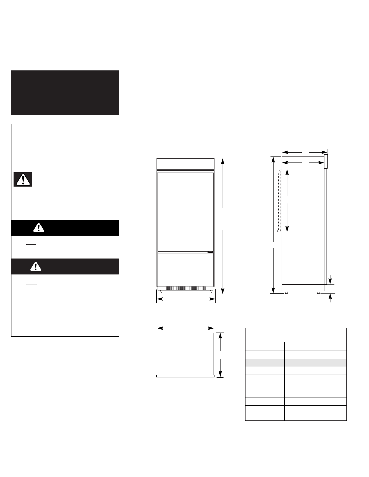
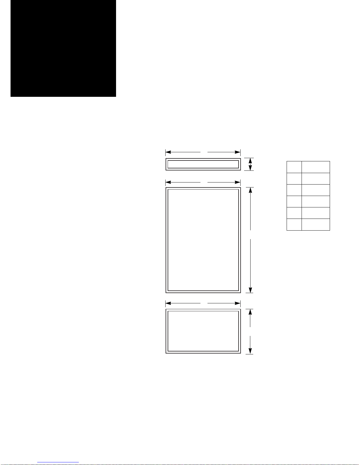
A 36" (91 cm)
B
Panel model 83-5/8" (212 cm)*
B 83-1/8" (211 cm)
C 25-1/8" (64 cm)
D 23-1/2" (60 cm)
E 3-1/2" (9 cm)*
F 83-1/8" (211 cm)*
G 24" (61 cm)
H 35" (89 cm)
I 25" (63.5 cm)
Before you
start...
Keep cardboard shipping piece or
plywood under refrigerator until it is
installed in the operating position.
Front view
A
C
D
G
E
F
Product dimensions
* Dimensions shown are for leg levelers
extended 1/8" (3 mm) below rollers. For
levelers fully extended 1-1/4" (32 mm)
below rollers, add 1-1/8" (29 mm) to this
dimension.
Important:
Observe all governing codes and
ordinances.
It is your responsibility to:
• Comply with installation specifications
and dimensions.
• Properly install refrigerator.
• Remove any moldings or decorative
panels that prevent the refrigerator
from being serviced.
• Make sure that you have these
materials necessary for proper
installation:
1/4" (6 mm) copper tubing with
shutoff valve
Top view
H
I
Your safety and the safety of others
is very important.
We have provided many important
safety messages in this manual and
on your appliance. Always read and
obey all safety messages.
This is the safety alert symbol.
This symbol alerts you to
hazards that can kill or hurt
you and others. All safety messages
will be preceded by the safety alert
symbol and the word “DANGER” or
“WARNING”. These words mean:
All safety messages will identify the
hazard, tell you how to reduce the
chance of injury, and tell you what can
happen if the instructions are not
followed.
You will be killed or seriously
injured if you don’t follow
instructions.
You can be killed or seriously
injured if you don’t follow
instructions.
Side view
1/4" (6 mm) compression fitting
6 – #8 x 3" (7.6 cm) wood screws
(Longer screws may be
required.)
2 – 2" x 4" x 32" (5 cm x 10 cm x
81 cm) min. wood boards
(See Page 4.)
• Assure that floor will support
refrigerator weight (more than
600 lb/272 kg), door panels,
and contents.
• Provide a properly grounded electrical
outlet.
• Assure that location will permit
appliance doors to open 90°
minimum.
B
See
Note.
WARNING
D ANGER
Panel model and wraparound
stainless steel door model
Trimless stainless
steel model
Important:
• Installer: Leave Installation Instructions
with the homeowner.
• Homeowner: Keep Installation
Instructions for future reference.
• Save these Installation Instructions for
the local electrical inspector’s use.
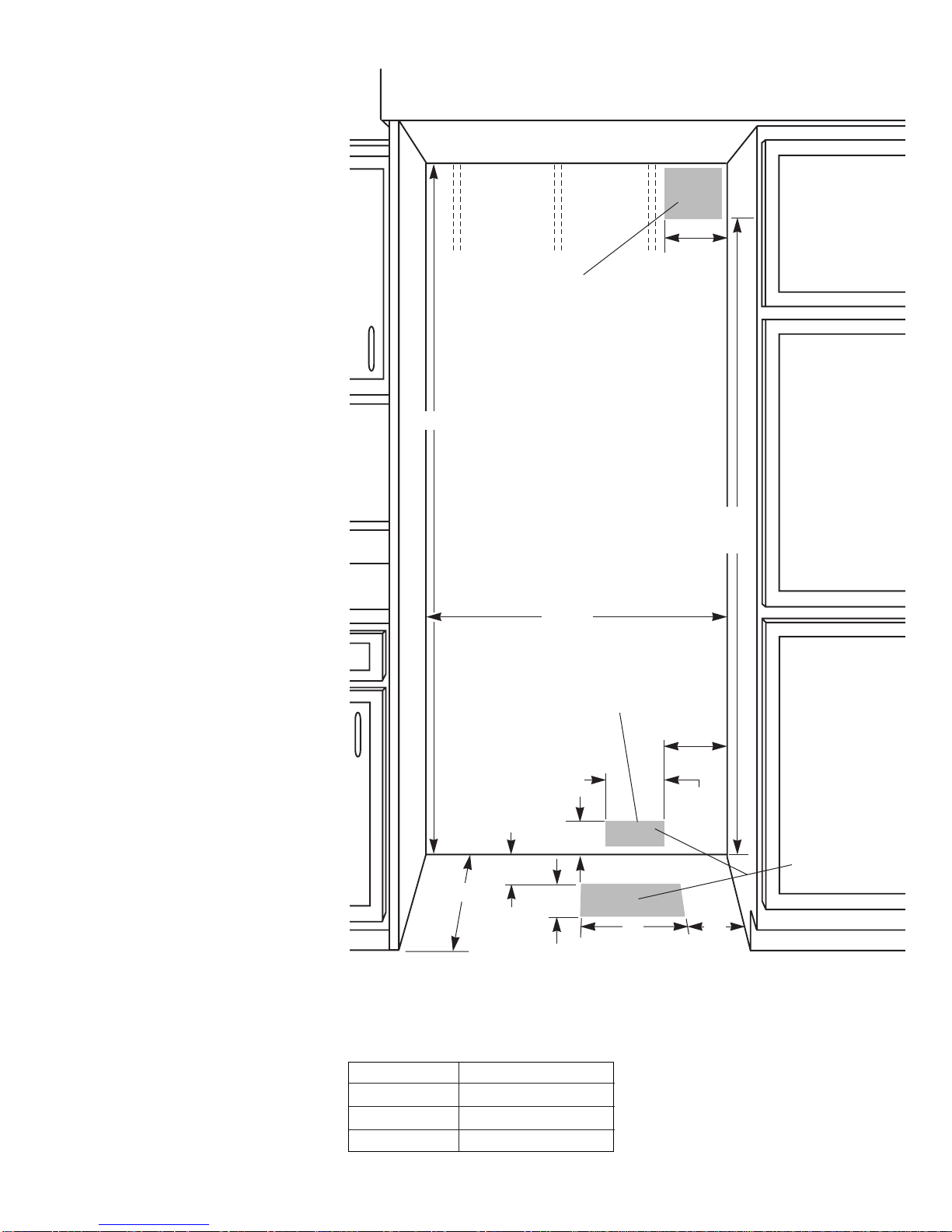
Width min.
Height min.
Height max.
Depth min.
35-1/2" (90 cm)
83-1/4" (211.5 cm)
84-3/4" (215 cm)
23-1/2" (60 cm)
Built-in opening
requirements &
dimensions
All dimensions ±1/8" (3 mm)
Grounded electrical
outlet location
Grounded electrical
outlet is required.
Mark stud
locations on
rear wall
80" - 90"
(203-229 cm)
above floor.
Floor: Must support refrigerator,
contents, and door panels.
Water line must
provide 15-100 psi
(103-690 kPa) water
pressure. Rough in
water line before
installing
refrigerator.
7"
(18 cm)
7"
(18 cm)
5-1/2"
(14 cm)
3"
(7.6 cm)
Install side panel (optional)
support board on rear wall
if opening depth is
25" (63.5 cm) or more.
Height
Depth
Opening dimensions
Page 3
Water line
location can be
through floor
or wall.
10"
(25 cm)
2" (5 cm)
1/2" (12 mm) hole for
plumbing can be
located anywhere
within shaded area.
The built-in refrigerator can be
installed:
• recessed in the cabinet opening.
• at the end of cabinets using a side
panel to enclose the side of the
refrigerator.
Select one method and use dimensions
given. Dimensions shown provide
0" (0 cm) clearance.
77"
(196 cm)
6"
(15 cm)
8"
(20 cm)
Width
A solid soffit or two, 2" x 4" x 32"
(5 cm x 10 cm x 81 cm) wood boards
to cover the width of the compressor
cover are required above the
refrigerator to prevent tipping
during use.
If solid soffit is more than 1 inch
(2.5 cm) above refrigerator, two
2"x 4" x 32" (5 cm x 10 cm x 81 cm)
wood boards must be installed on
the wall 1/4 inch (6 mm) above the
refrigerator cover. The bottom
surface of the boards should be
84 inches (213 cm) from floor. Boards
must be long enough to fully cover
width of compressor cover.
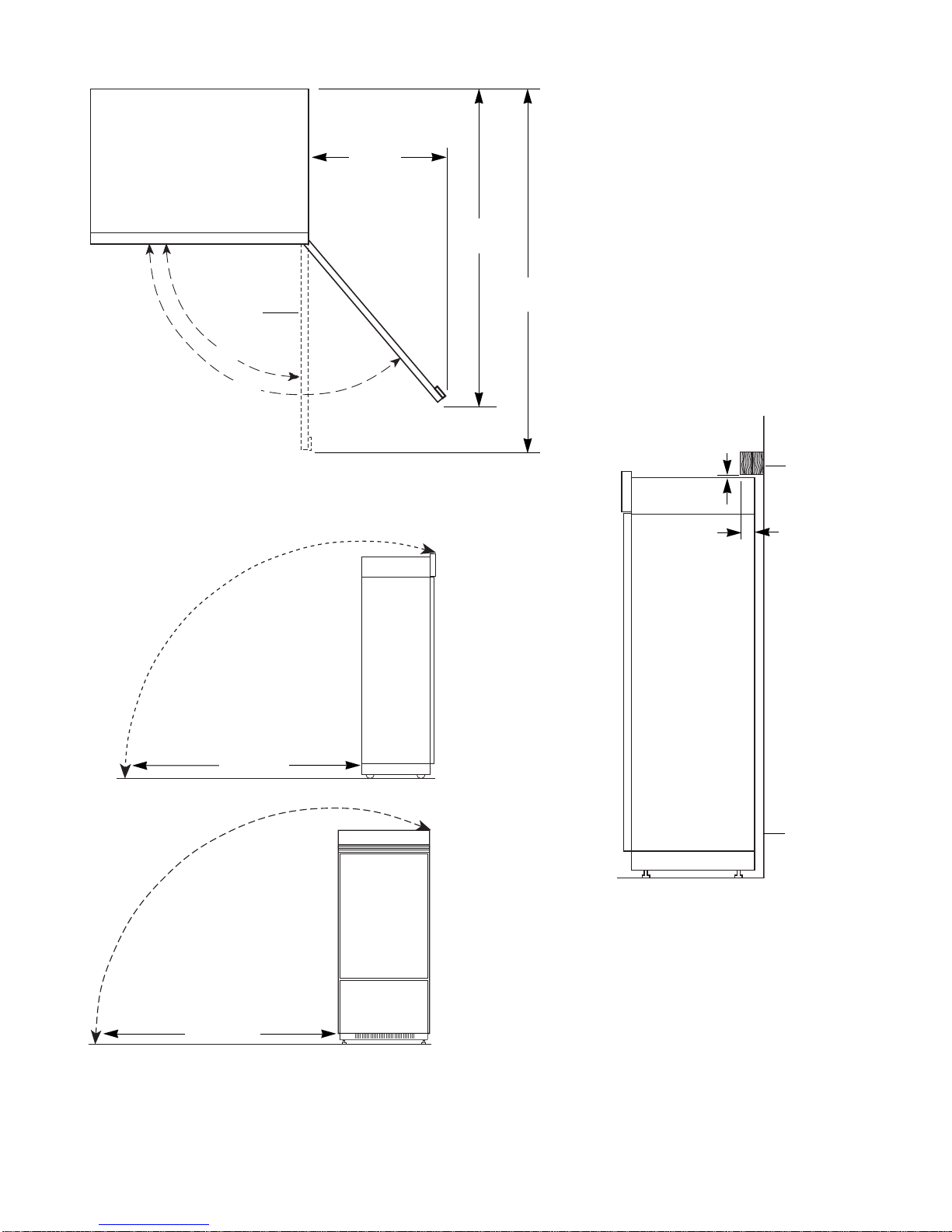
Refrigerator
door
130°
59"
(150 cm)
51"
(130 cm)
Door swing dimensions
If boards are placed before installation of
refrigerator, locate boards so the bottom surface of
the boards are 84 inches (213 cm) from the floor.
During installation, raise the refrigerator up so there
is 1/4 inch (6 mm) maximum between top of
refrigerator and bottom of anti-tip boards.
If solid soffit is 1 inch (2.5 cm) above
refrigerator, anti-tip wood boards are not required.
If solid soffit is not available or soffit is more than
1 inch (2.5 cm) above cover, center wood boards
on rear wall 1/4 inch (6 mm) maximum above
refrigerator. Attach wood boards to wall studs with
wood screws — making sure that screws are
engaged in wall studs 1-1/2 inch (3.8 cm) minimum
and that boards extend 2 inches (5 cm) minimum
over the top rear of refrigerator compressor cover.
Two, 2" x 4" x
32" (5 cm x
10 cm x 81 cm)
anti-tip wood
boards
Attach to wall
studs with six,
#8 x 3" (76 mm)
(or longer)
wood screws.
Boards must be
long enough to
fully cover
width of
compressor
cover.
1/4" (6 mm) max.
2" (5 cm)
min.
rear
wall
Page 4
Anti-tip requirements
Tipping radius
Forward/backward
tipping radius
Side
tipping radius
87-1/4"
(222 cm)
90-1/2"
(230 cm)
Location must permit doors to open to
90° min. For panel models, allow 1 inch
(2.5 cm) min. space between refrigerator
side and corner wall. For wraparound
stainless steel models, allow 4-1/2 inch
(11.5 cm) min. space between
refrigerator side and corner wall.
23"
(58 cm)
90°
Parts that
must be
ordered
separately or
custom made
The custom panel weight must NOT
exceed amounts listed.
Panels weighing more than amounts
listed may cause product damage.
A
C
E
D
F
B
Refrigerator door
panel
Maximum
weight:
60 pounds
(27 kg)
Freezer
door panel
Maximum
weight:
20 pounds
(9 kg)
Page 5
Top grille panel
maximum
weight
10 pounds
(4.5 kg)
NOTE: Dimensions shown have a
±1/16 (1.5 mm) tolerance. Panels
that are more than 1/4" (6 mm) thick
must be routed. If using routed
panels, add 1/16" (1.5 mm) to
dimensions shown.
If panels are less than 1/4" (6 mm)
thick, install a filler panel between
doors and decorative panels.
72" stainless steel Panel kit, Part number 4392934, is for wraparound stainless
steel door models only. It allows 2 units (one left-hand swing and one right-hand
swing) to be installed side by side with a single grille.
A
B
C
D
E
F
35-11/16"
(90.7 cm)
5-3/8"
(13.7 cm)
34-1/4"
(87 cm)
49"
(124.5 cm)
34-1/4"
(87 cm)
20-1/4"
(51.4 cm)
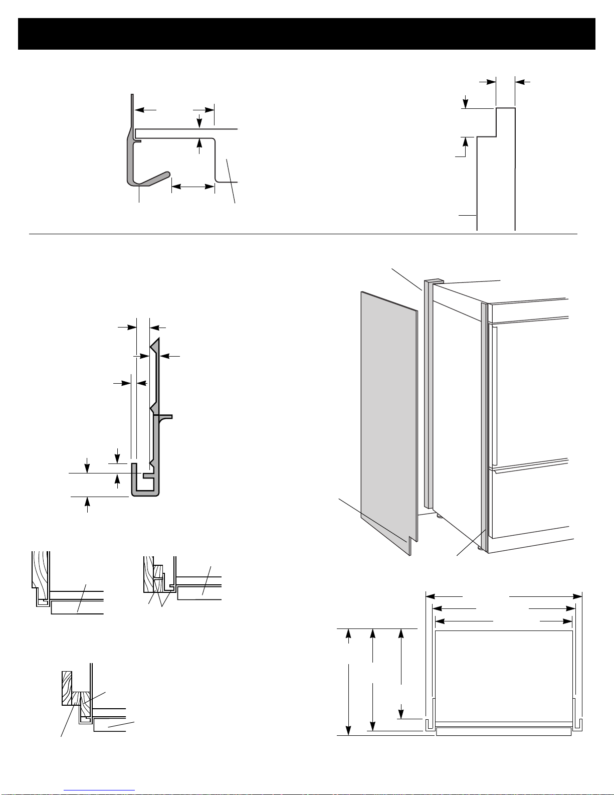
Panel models and wraparound stainless steel door models
Thickness:
1/2" (12 mm)
minimum to
prevent warping.
Width and height:
depend on
installation type.
Notches for toe
panel recess
(if desired).
Determine
installation height
before cutting
notches.
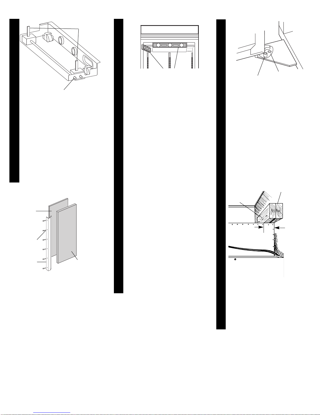
If side panel will be installed inside side trim
and the side panel is more than 1/4" (6 mm)
thick, route front edge of panel to fit trim piece.
side panel
support nailer
side trim piece
End view of side trim piece
5/32"
(4 mm)
1/4"
(6 mm)
1/16"
(1.6 mm)
3/16"
(4.8 mm)
13/32"
(10.5 mm)
side panel inside
side trim piece
side panel outside
side trim piece
door
door
Side panels
door
recessed side panel
outside side trim piece
36" (91 cm)
35.5" (90 cm)
35" (89 cm)
25"
(63.5 cm)
23-3/8"
(59.4 cm)
22-13/16"
(57.9 cm)
Rout front edge of support board or attach
1/4" board for retention in cabinet side trim.
Attach support board with
screw or adhesive compatible
with aluminum and wood.
support
board
support
board
Dimensions for
routing panel
edges
Side view
3/4"
(19 mm)
min.
1/4"
(6 mm) max.
panel
End view of handle side of panel
panel
handle
2" (5 cm)
min.
1/4" (6mm )max.
Custom panels
more than 1/4"
(6 mm) thick:
Route entire length
or selected areas of
handle side of
panels 3-1/4"
(8.25 cm).
3-1/4"
(8.25 cm)
min.
Page 6
Electrical &
water supply
requirements
A 120-volt, 60-Hz, AC-only, 15- or 20ampere, fused, electrical supply is
required. A time-delay fuse or circuit
breaker is recommended. It is
recommended that a separate circuit
serving only this appliance be provided.
This appliance is equipped with a power
supply cord having a 3-prong ground
plug. To minimize possible shock hazard,
the cord must be plugged into a mating
3-prong, ground-type outlet, grounded
in accordance with the National
Electrical Code, ANSI/NFPA 70 — latest
edition* or Canadian Electrical Code,
C22.1-1982 and C22.2 No. 01982 (or
latest edition)**, and all local codes and
ordinances.
Copies of the standard listed may be
obtained from:
* National Fire Protection Association
Batterymarch Park
Quincy, Massachusetts 02269
** Canadian Standard Association
178 Rexdale Boulevard
Etobicoke, Ontario M9W 1R3
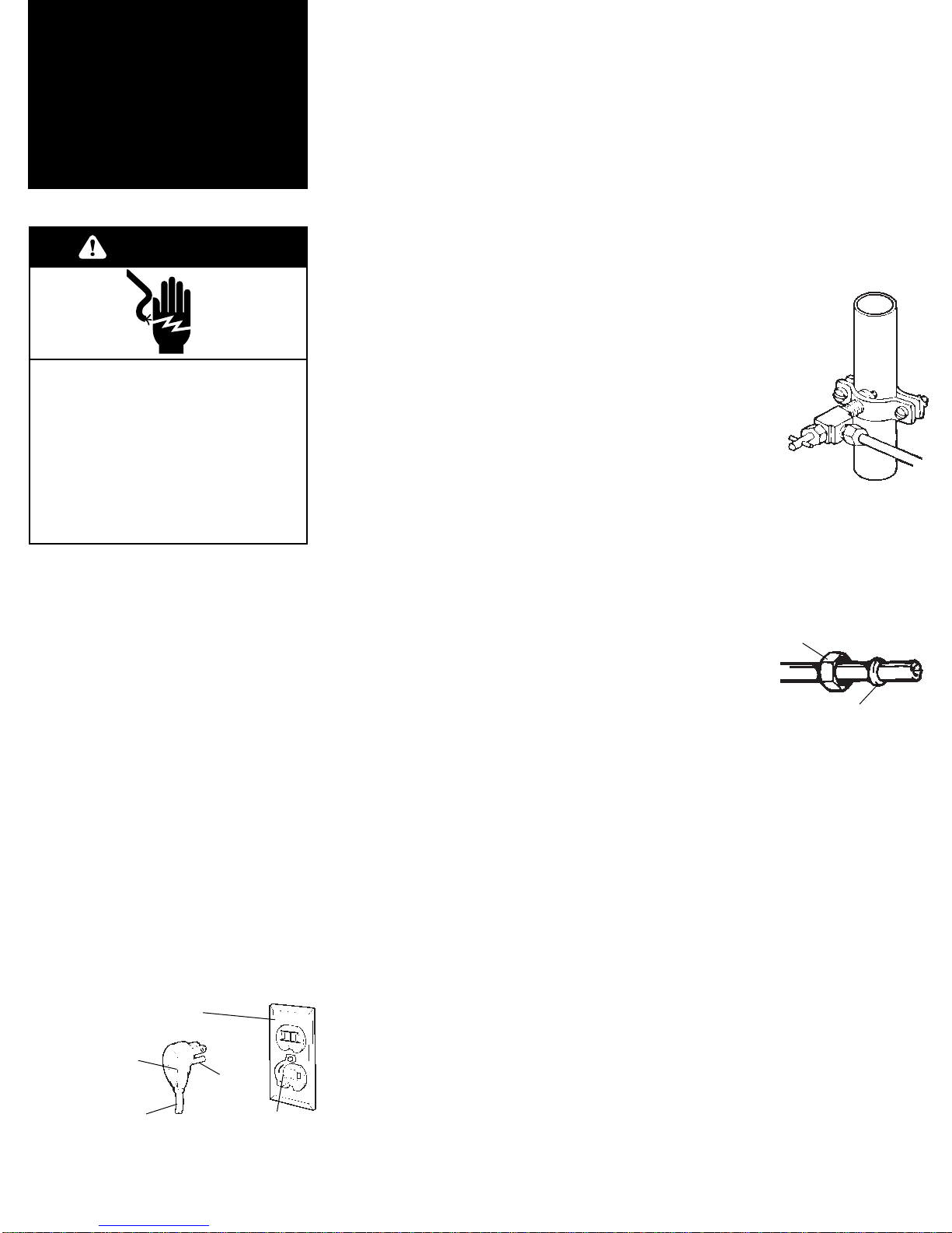
Electrical requirements
ground
prong
power supply
cord
retainer
Water supply requirements
Use only 1/4" (6 mm) copper tubing
for water line.
Do Not install copper tubing in area
where temperatures drop below
32°F (0°C).
Before attaching copper tubing to
refrigerator, flush at least 2 quarts
(1.9 L) of water through the copper
tubing and into a bucket to get rid
of any particles in the water line.
Do Not overtighten clamp or sleeve.
This will crush copper tubing.
Check for leaks around saddle valve.
3. Turn OFF main water supply. Turn ON
nearest faucet long enough to clear line
of water.
4. Vertical cold water line: Use
grounded electric drill or hand drill to
drill 3/16" (4.5 mm) hole in an easily
accessible location in water line.
Horizontal cold water line: Use
grounded electric drill or hand drill to
drill 3/16" (4.5 mm) hole in the top of
the water line. This will keep sediment
from collecting in valve.
5. Position washer over hole in
water line. Turn saddle valve
handle clockwise to expose
piercing lance a maximum of
3/16" (4.5 mm). Align
piercing lance over hole in
water line. Place both
halves of saddle valve
bracket against water
line. Turn saddle
valve handle
clockwise until piercing lance
enters hole in water line and is
firmly seated. The saddle valve is not in
the closed position. Tighten packing nut.
Evenly and firmly tighten bracket screws
so washer will make a water-tight
connection. Do Not overtighten
screws; copper tubing could be
crushed.
6. Check that both
ends of copper
tubing are cut
square. Slide
compression nut
and sleeve onto copper
tubing. Insert end of copper tubing
completely into valve outlet. Tighten
compression nut to outlet with adjustable
wrench. Do Not overtighten.
7. Turn on main water supply. Check for
leaks. Turn saddle valve handle
counterclockwise and run water through
copper tubing and into a bucket. Turn
saddle valve handle clockwise to shut off
water to copper tubing.
8. Route copper tubing to refrigerator
area.
compression nut
sleeve
3-prong ground-type
outlet
3-prong
ground plug
If codes permit and a separate
ground wire is used, it is
recommended that a qualified
electrician determine that the ground
path is adequate.
Do not ground to gas pipe.
Check with a qualified electrician if
you are not sure the appliance is
properly grounded.
Do not have a fuse in the neutral or
ground circuit.
It is the customer’s responsibility:
To contact a qualified electrical
installer.
To assure that the electrical
installation is adequate and in
conformance with the National
Electrical Code, ANSI/NFPA 70 —
latest edition* or Canadian Electrical
Code, C22.1-1982 and C22.2 No.
01982 (or latest edition)**, and all
local codes and ordinances.
WARNING
Electrical Shock Hazard
Plug into a grounded 3-prong
outlet.
Do not remove ground prong.
Do not use an adapter.
Do not use an extension cord.
Failure to follow these
instructions can result in death,
fire, or electrical shock.
Water line to refrigerator must provide
15-100 psi (103-690 kPa) water
pressure.
To calculate length of 1/4" (6 mm)
O.D. copper tubing needed:
1. Locate a vertical 1/2" (1.2 cm) to
1-1/4" (3.2 cm) COLD water line near
refrigerator area. A horizontal COLD
water line can be used if directions in
Step 4 are carefully followed.
2. Measure distance from cold water
line to refrigerator area. Add 24" (61
cm) to this measurement.
To rough in water line:
Page 7
Check that water supply line has
been flushed. See Page 7.
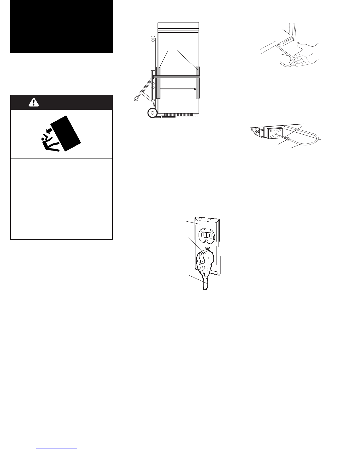
6.Pull water supply line out from
underneath refrigerator. Carefully make
a 3-1/2" or less (180°) hook-shaped end
in the water supply line.
1.Remove and save literature
package and parts bag taped to
refrigerator door. Remove four brackets
(two on each side) attaching shipping
base to refrigerator bottom.
Do not remove tape and door bracing
until refrigerator is in final position.
Installation
steps
Do Not lower the refrigerator
against the shipping base when
removing the shipping base.
Do Not remove protective film until
refrigerator is in operating position.
All four leveling legs must contact
the floor to support and stabilize the
full weight of the refrigerator.
Keep cardboard shipping piece or
plywood under refrigerator until it is
installed in operating position.
Parts supplied for installation:
• base grille
• miscellaneous parts bag
Check that all parts were included.
3.Place pieces of shipping carton
on the floor when rolling dolly and
refrigerator into the house. Move
refrigerator close to built-in opening.
4.Set power
switch at top of
cabinet to “OFF”
position.
Plug power supply cord
into grounded outlet.
Install retainer on
grounded outlet
using screw from
parts bag.
5.Place top of cardboard
carton or plywood under refrigerator.
Remove dolly. Open both doors and
remove all boxes, parts packages and
packing materials from refrigerator and
freezer compartments. Do Not remove
protective film.
Move the refrigerator straight back and
evenly into the opening. Check that:
• copper tubing is not kinked.
• power supply cord is on top of
refrigerator next to cover.
retainer
grounded
outlet
power
supply
cord
2.Place appliance dolly under the
freezer side of refrigerator and loosely
wrap dolly strap around refrigerator.
Insert carton corner posts between
strap and side trim and handles.
Carefully tighten strap, making sure
side trim and handles are protected.
copper
water line to
valve
lower right hand
front corner of
refrigerator
Do not kink water supply line. Remove
cap from water valve. Slide
compression nut, then ferrule, onto
water supply line. Insert water supply
line completely into water valve.
Tighten compression nut to water
valve. Do not overtighten.
Turn water supply line valve to “Open”
position. Turn refrigerator switch to
“On” position. Wait a few minutes.
Check water line connections for leaks.
1/4" (6 mm)
compression
nut
copper line
to valve
ferrule
Tip Over Hazard
Refrigerator is top heavy and tips
easily when not completely
installed.
Keep doors taped closed until
refrigerator is completely
installed.
Use two or more people to move
and install refrigerator.
Failure to do so can result in
death or serious injury.
WARNING
Page 8
corner posts
over side trim/
handle
decorative
panel
Filler panel
required if
panels are less
than 1/4"
(6 mm) thick.
If panels are
more than
1/4" (6 mm)
thick, route
panel edges
on all sides.
door
handle
nylon
washers
Page 9
13.If solid soffit is 1 inch
(2.5 cm) above refrigerator, anti-
tip wood boards are not required.
If solid soffit is not available or
soffit is more than 1 inch
(2.5 cm) above refrigerator,
locate wall studs in refrigerator
opening. Center one wood board
on rear wall 1/4 inch (6 mm)
maximum above refrigerator.
Attach wood board to wall studs
with wood screws — making sure
that screws are engaged in wall
studs 1-1/2 inches (3.8 cm)
minimum. Attach second wood
board to the front of the first
board. Wood boards must extend
2 inches (5 cm) minimum over the
top rear of the refrigerator
compressor cover.
8.Wraparound stainless steel
door models: go to step 9.
Panel models: Remove all tape and
door bracing from refrigerator and
freezer doors. Remove screws attaching
handles to door frames. Slide decorative
door panels into door frames.
If panels are less than 1/4" (6 mm)
thick, install a filler panel between door
and decorative panel.
If panels are more than 1/4" (6 mm)
thick, route panel edges on all sides.
two, 2" x 4" x 32"
(5 cm x 10 cm x 81 cm)
anti-tip wood boards
Center
board 1/4"
(6 mm) max.
above
refrigerator.
cover
2" (5 cm)
Attach to
wall studs
with six,
#8 x 3"
(7.6 cm)
(or longer)
wood
screws.
Boards
must be
long
enough to
fully cover
width of
compressor
cover.
10.Check the alignment of
the refrigerator door.
If the refrigerator door needs to
be adjusted left or right or in or
out, loosen the 3/8" hex head
screws in top hinge.
11.Replace door handles.
If door handles are not
aligned, loosen all handle screws
and adjust door handles as
needed. Tighten screws.
If any of the white door screws
(white trim models only) are
damaged, replace them with
additional screws provided in the
parts package.
C
R
I
T
I
C
A
L
S
T
E
P
S
door stop set screw
(130° position)
90° position
bottom hinge
12. Check that the
refrigerator door can open
freely. If door opens too wide,
remove door stop screw from
bottom door hinge. Hold door
open to a position that is less
than 90°. Replace door stop
screw in the 90° door stop
position in bottom hinge and
tighten screw. If door does not
clear countertop after door has
been adjusted, countertops may
need to be mitered.
C
R
I
T
I
C
A
L
S
T
E
P
9.Open door. Place a level
against inside top of refrigerator as
shown. Adjust leveling legs until
refrigerator is level. Check that all
four leveling legs contact floor and
support the full weight of the
refrigerator. Door panels need to
be installed before leveling.
Check that
refrigerator is
level.
C
R
I
T
I
C
A
L
S
T
E
P
leveling
legs
Use 5/16" (8 mm)
socket and ratchet.
7.Use socket wrench to turn leg
levelers on both sides of
refrigerator to the right (clockwise)
until refrigerator weight is
supported by leveling legs. The
rollers should be off the floor.
Note: All four leveling legs must
contact the floor to support and
stabilize the full weight of
refrigerator. Rollers are for
moving refrigerator and not for
permanent support.
rear
front
 Loading...