

Page 1

KAR-13
TECHNICAL EDUCATION
OUTDOOR AUTOMATIC
ICE MAKER
Model KUIO15NNLS
JOB AID 4317309
Page 2

FORWARD
This KitchenAid Job Aid, “Outdoor Automatic Ice Maker,” (Part No. 4317309), provides the
technician with information on the installation, operation, and service of the Outdoor Automatic Ice
Maker. It is to be used as a training Job Aid and Service Manual. For specific information on the
model being serviced, refer to the “Use and Care Guide,” or “Wiring Diagram” provided with the
ice maker.
The Wiring Diagram and Strip Circuits used in this Job Aid are typical and should be used for
training purposes only. Always use the Wiring Diagram supplied with the product when servicing
the unit.
GOALS AND OBJECTIVES
The goal of this Job Aid is to provide detailed information that will enable the service technician to
properly diagnose malfunctions and repair the KitchenAid Outdoor Automatic Ice Maker.
The objectives of this Job Aid are to:
• Understand and follow proper safety precautions.
• Successfully troubleshoot and diagnose malfunctions.
• Successfully perform necessary repairs.
• Successfully return the ice maker to its proper operational status.
WHIRLPOOL CORPORATION assumes no responsibility for any repairs made
on our products by anyone other than Authorized Service Technicians.
Copyright © 2003, Whirlpool Corporation, Benton Harbor, MI 49022
- ii -
Page 3

TABLE OF CONTENTS
Page
GENERAL............................................................................................................................... 1-1
Safety First......................................................................................................................... 1-1
KitchenAid Model & Serial Number Designations.............................................................. 1-3
Model & Serial Number Label And Wiring Diagram Locations .......................................... 1-4
Specifications..................................................................................................................... 1-5
Outdoor Ice Maker Warranty ............................................................................................. 1-6
INSTALLATION INFORMATION ........................................................................................... 2-1
Electrical Supply Requirements ......................................................................................... 2-1
Water Supply And Drain Connections ............................................................................... 2-2
THEORY OF OPERATION ..................................................................................................... 3-1
The Controls ...................................................................................................................... 3-1
Water And Refrigerant Circuit ............................................................................................ 3-2
COMPONENT ACCESS ......................................................................................................... 4-1
Component Locations ........................................................................................................ 4-1
Removing The Water Inlet Valve ....................................................................................... 4-2
Removing The Evaporator ................................................................................................. 4-3
Removing The Water Recirculation Pump......................................................................... 4-4
Removing The Evaporator Thermistor............................................................................... 4-8
Removing The Bin Thermostat ........................................................................................ 4-10
Removing The Hot Gas Valve And Solenoid ................................................................... 4-12
Removing The Master Switch, Recirculation Pump Motor Capacitor,
And Electronic Control Board ....................................................................................... 4-14
Removing The Condenser Fan Motor ............................................................................. 4-16
Removing The Condenser ............................................................................................... 4-18
Removing The Compressor ............................................................................................. 4-20
Removing The Door, Door Gasket, And Top Cover ........................................................ 4-22
COMPONENT TESTING ........................................................................................................ 5-1
Water Inlet Valve Solenoid ................................................................................................ 5-1
Water Recirculation Pump ................................................................................................. 5-1
Evaporator Thermistor ....................................................................................................... 5-2
Bin Thermostat .................................................................................................................. 5-2
Hot Gas Valve Solenoid..................................................................................................... 5-3
Master Switch .................................................................................................................... 5-3
Recirculation Pump Motor Capacitor ................................................................................. 5-4
Condenser Fan Motor ........................................................................................................ 5-4
Compressor, Overload, & Relay ........................................................................................ 5-5
- iii -
Page 4

Page
DIAGNOSIS & TROUBLESHOOTING ................................................................................... 6-1
Timing Chart ...................................................................................................................... 6-1
Troubleshooting Chart ....................................................................................................... 6-2
WIRING DIAGRAM & STRIP CIRCUITS ............................................................................... 7-1
Wiring Diagram .................................................................................................................. 7-1
Strip Circuits ...................................................................................................................... 7-2
TECH TIPS ............................................................................................................................. 8-1
Cleaning The Ice Maker..................................................................................................... 8-1
Routine Cleaning ......................................................................................................... 8-1
Cleaning The Spray Assembly .................................................................................... 8-2
- iv -
Page 5

GENERAL
SAFETY FIRST
Your safety and the safety of others is very important.
We have provided many important safety messages in this Job Aid and on the appliance. Always
read and obey all safety messages.
This is the safety alert symbol.
This symbol alerts you to hazards that can kill or hurt you and others.
All safety messages will follow the safety alert symbol and either the word
“DANGER” or “WARNING.” These words mean:
You can be killed or seriously injured if you don’t
DANGER
WARNING
All safety messages will tell you what the potential hazard is, tell you how to reduce the chance
of injury, and tell you what can happen if the instructions are not followed.
immediately follow instructions.
You can be killed or seriously injured if you don’t
follow instructions.
ELECTRICAL POWER SUPPLY &
GROUNDING REQUIREMENTS
WARNING
Electrical Shock Hazard
Disconnect power before servicing.
Replace all parts and panels before
operating.
Failure to do so can result in death or
electrical shock.
WARNING
Electrical Shock Hazard
Plug into a grounded 3-prong outlet.
Do not remove ground prong.
Do not use an adapter.
Do not use an extension cord.
Failure to follow these instructions can
result in death, fire, or electrical shock.
1-1
Page 6

WARNING
Electrical Shock Hazard
Connect green ground wire to ground
screw.
Failure to do so can result in death or
electrical shock.
IMPORTANT
Electrostatic Discharge (ESD)
Sensitive Electronics
ESD problems are present everywhere.
ESD may damage or weaken the electronic control assembly. The new control
assembly may appear to work well after
repair is finished, but failure may occur at
a later date due to ESD stress.
• Use an antistatic wrist strap. Connect the
wrist strap to the green ground connection point, or to an unpainted metal surface in the appliance.
- OR -
• Touch your finger repeatedly to a green
ground connection point, or to an unpainted metal surface in the appliance.
• Before removing the part from its package, touch the antistatic bag to a green
ground connection point, or to an unpainted metal surface in the appliance.
• Avoid touching electronic parts, or terminal contacts. Handle the electronic control assembly by the edges only.
• When repackaging the failed electronic
control assembly in an antistatic bag,
observe the previous instructions.
1-2
Page 7

KITCHENAID MODEL & SERIAL NUMBER DESIGNATIONS
MODEL NUMBER
MODEL NUMBER K UI O 15 NN L S 0
INTERNATIONAL SALES IND.
OR MARKETING CHANNEL
IF PRESENT
PRODUCT GROUP
K = KITCHENAID
PRODUCT IDENTIFICATION
UI = UNDERCOUNTER ICE MAKER
MERCHANDISING SCHEME
O = OUTDOOR
CAPACITY / SIZE / SERIES / CONFIGURATION
15 = 15" WIDE
FEATURES
NN = NON-PUMP, NON-REVERSIBLE DOOR
YEAR OF INTRODUCTION
L = 2002
COLOR CODE
S = STAINLESS STEEL
ENGINEERING CHANGE (NUMERIC)
SERIAL NUMBER
SERIAL NUMBER EH P 04 54321
DIVISION RESPONSIBILITY
E = EVANSVILLE, IN / SOURCED
YEAR OF PRODUCTION
P = 2003, R = 2004
WEEK OF PRODUCTION
04 = 4th WEEK
PRODUCT SEQUENCE NUMBER
1-3
Page 8

MODEL & SERIAL NUMBER LABEL
AND WIRING DIAGRAM LOCATIONS
The Model/Serial Number label and Wiring Diagram locations are shown below.
Model & Serial Number Label Location
Wiring Diagram Location
(On Rear Of Front Panel)
1-4
Page 9

SPECIFICATIONS
(
)
(
)
(
)
(
)
AC Power Supply .........................................................................104 To 127 VAC, 60 Hz
Amperage....................................................... 3.4A (5 Minute Freeze @ 104°F/WT 80°F)
Minimum Circuit Capacity ................................................................................... 15 Amps
Maximum Fuse Size............................................................................................ 15 Amps
Ice Production Per 24 Hr. (Approximate) ...........................................................................
Ambient
Temp (°F/°C)
70/21 51 lbs. (23 kg) 46 lbs. (21 kg) 43 lbs. (19 kg)
80/27 47 lbs. (22 kg) 40 lbs. (18 kg) 38 lbs. (17 kg)
90/32 46 lbs. (21 kg) 35 lbs. (16 kg) 32 lbs. (14 kg)
100/38 40 lbs. (18 kg) 34 lbs. (15 kg) 29 lbs. (13 kg)
Water Temperature (°F/°C)
50/10 70/21 90/32
Ice Shape ............................................................................................................. Top Hat
Ice Production Per Cycle........................................................ 24 pcs, 0.595 Ibs. (0.27 kg)
Storage Capacity (Approximate) ............................................................. 28 Ibs. (12.7 kg)
Bin Control Setting ...................................................................................22 Ibs. (10.0 kg)
Exterior Dimensions (W x D x H) ................... 14.9″ x 22.6″ x 33.5″ (378 x 575 x 850mm)
Exterior Finish ....................................... Stainless Steel, Plastic, Galvanized Steel (Rear)
Net Weight ..................................................................................................88 Ibs. (40 kg)
Cube Control System ....................................................... Thermistor & Electronic Control
Harvesting Control System ............................................................. Hot Gas & Thermistor
Ice Making Water Control...................................................................... Electronic Control
Bin Control System ......................................................................................... Thermostat
Refrigerant .............................................................................................................. R134a
Ambient Temperature .................................................................................... 45 To 100°F
Water Supply Pressure ............................................................................... 7 To113 PSIG
Electrical Consumption
Ambient
Temp (°F/°C)
70/21 222 Watts 228 Watts 235 Watts
80/27 227 Watts 237 Watts 242 Watts
90/32 228 Watts 244 Watts 250 Watts
100/38 237 Watts 246 Watts 255 Watts
Ambient
Temp (°F/°C)
70/21 3.1 min. 2.0 min. 2.0 min.
80/27 3.0 min. 2.0 min. 2.0 min.
90/32 3.0 min. 2.4 min. 2.0 min.
100/38 3.0 min. 2.0 min. 2.1 min.
Water Temperature
50/10 70/21 90/32
Water Temperature
50/10 70/21 90/32
°F/°C
°F/°C
Temp (°F/°C)
Temp (°F/°C)
Water Consumption (Per 24 Hrs.)
Ambient
70/21 44 Gal. 38 Gal. 33 Gal.
80/27 39 Gal. 31 Gal. 27 Gal.
90/32 38 Gal. 24 Gal. 20 Gal.
100/38 31 Gal. 23 Gal. 16 Gal.
Ambient
70/21 16 min. 19 min. 23 min.
80/27 18 min. 21 min. 26 min.
90/32 19 min. 24 min. 29 min.
100/38 25 min. 29 min. 33 min.
Water Temperature
50/10 70/21 90/32
Freeze Cycle TimeHarvest Cycle Time
Water Temperature
50/10 70/21 90/32
°F/°C
°F/°C
1-5
Page 10
OUTDOOR ICE MAKER WARRANTY
1-6
Page 11

INSTALLATION INFORMATION
ELECTRICAL SUPPLY REQUIREMENTS
WARNING
Electrical Shock Hazard
• A 115 Volt, 60 Hz, AC only 15 ampere electrical
supply, properly grounded in accordance
with the National Electrical Code and local
codes and ordinances, is required.
• It is recommended that a separate circuit,
serving only the ice maker, be provided. Use
a receptacle which cannot be turned off by a
switch or pull chain.
Plug into a grounded 3 prong outlet.
Do not remove ground prong.
Do not use an adapter.
Do not use an extension cord.
Failure to follow these instructions can
result in death, fire, or electrical shock.
Before you move the ice maker into its final
location, it is important to make sure you have
the proper electrical connection:
Recommended Grounding Method
For personal safety, this appliance must be
grounded. This appliance is equipped with a
power supply cord having a 3-prong grounding
plug. To minimize possible shock hazard, the
cord must be plugged into a mating, 3- prong,
grounding-type wall receptacle, grounded in
accordance with the National Electrical Code
and local codes and ordinances. If a mating
wall receptacle is not available, it is the personal responsibility of the customer to have a
properly grounded, 3-prong wall receptacle
installed by a qualified electrician.
2-1
Page 12

WATER SUPPLY AND DRAIN CONNECTIONS
CAUTION: To prevent damage to the freezer
mechanism, do not operate this ice maker
when the water supply is OFF, or if the pressure is below 10 PSIG (0.7 bar), the recommended water pressure. Stop the ice maker
until proper water pressure is resumed.
• The water supply inlet is 1/2-14 NPT and
must only be connected to a potable water
supply.
• A water supply line shut-off valve and drain
valve must be installed.
• Water supply pressure should be a minimum
of 10 PSIG (0.7 bar), and a maximum of 113
PSIG (7.5 bar). If the pressure exceeds 113
PSIG (7.5 bar), use a pressure reducing
valve.
Ice Maker
• The drain outlet hose is 5/8″ (16mm) I.D. and
internally connected with a 2/3″ (17mm) O.D.
drain outlet.
• The drain must be 1/4″ fall-per-foot (2 cm
fall-per-meter) on horizontal runs for optimum flow.
• Keep a 2 vertical inch (5 vertical cm) air gap
or more between the drain pipe end and the
sink.
• The drain pipe must be used to prevent a
backflow into the storage bin.
• This ice maker should be installed in accordance with applicable national, state,
and local regulations.
Vent
1/4" Fall-Per-Foot
To Approved Floor Drain
Water Supply Inlet = 1/2-14 NPT
Shutoff Valve
Drain Valve (Air or CO2 For
Long Term Storage)
Bin Drain Outlet
Hose 5/8" I.D.
2-2
Page 13

THEORY OF OPERATION
THE CONTROLS
ICE MAKING CONTROL
The freeze and harvest cycles are controlled
by a thermistor and an electronic control.
The electronic controller uses a thermistor that
is attached to the top of the evaporator to
monitor the evaporator temperature. When the
thermistor signals 28°F (–2°C), the control
begins to count down 10 minutes. The electronic control then switches the contacts of
relays X1 and X2, which stops the pump and
fan motors, and engerizes the hot gas and
water valves. This completes the freeze cycle,
and starts the harvest cycle.
HARVEST CONTROL
The ice cubes formed inside the ice making
cells are released by hot gas warming the
evaporator. When a small portion of the ice
melts on the ice making cells interior, the ice
drops down the ice guide into the storage bin.
When the evaporator is warmed further (to
approximately 45°F / 7°C), the thermistor senses the temperature rise, and the electronic
controller begins to count down 50 seconds.
The controller then switches the contacts of the
relays, which starts the pump and fan motors,
and de-energizes the hot gas and water valves.
This completes the harvest cycle, and starts
the freeze cycle. The harvest and freeze cycles
will continue until the bin is full of ice and the bin
thermostat is satisfied.
At low temperature conditions where the harvest cycle exceeds 3 minutes, the water valve
will de-energize after 3 minutes.
At the initial start, or after a power failure, the
ice maker will begin in the harvest cycle, because the compressor is under a “no load”
condition (hot gas valve is energized). During
this time, any ice that is present on the evaporator will be removed.
In the initial cycle at startup, or after shutdown
for bin control, water is supplied for 80 seconds. The water valve de-energizes approximately 30 seconds after the freeze cycle starts.
NO ADJUSTMENT
The thermistor and electronic control are factory adjusted to produce constant ice all year,
and are not affected by changes in the ambient
and water temperatures. No adjustment is required for any frequency 50/60Hz or ambient
temperature from 45 to 100°F.
No Adjustment.
Controls Are Sealed.
If Seals Are Broken,
Replace Control.
3-1
Page 14

WATER AND REFRIGERANT CIRCUIT
3-2
Page 15

COMPONENT ACCESS
This section instructs you on how to service each component inside the Outdoor Automatic Ice
Maker. The components and their locations are shown below.
COMPONENT LOCATIONS
TOP OF UNIT
Bin Thermostat
(On Rear Panel)
Evaporator Thermistor
Water Inlet Valve
Hot Gas Valve
(Behind Compressor)
Water Recirculation Pump
Evaporator
BOTTOM FRONT OF UNIT
Compressor
Condenser
Recirculation Pump
Motor Capacitor
Condenser Fan Motor
Master Switch
Electronic Control Board
4-1
Page 16
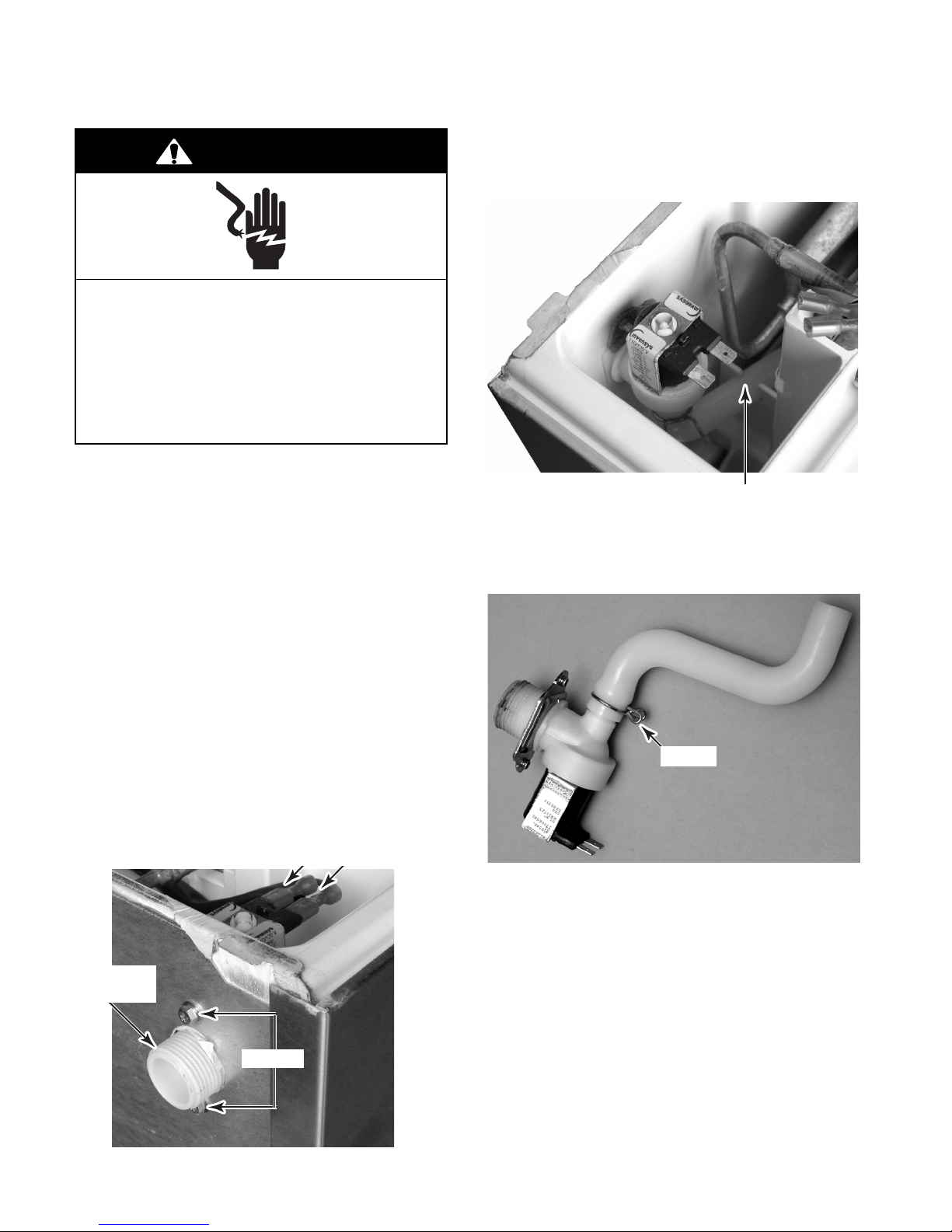
REMOVING THE WATER INLET VALVE
WARNING
Electrical Shock Hazard
Disconnect power before servicing.
Replace all parts and panels before
operating.
Failure to do so can result in death or
electrical shock.
1. Unplug ice maker or disconnect power.
2. Turn off the water supply to the ice maker.
10. Lift the water inlet valve, release the inlet
fill tube from the molded retainer, and
remove them from the ice maker.
Inlet Fill Tube In Retainer
3. Move the ice maker to gain access to the
rear of the unit.
4. Disconnect the drain outlet hose from the
ice maker.
5. Disconnect the water inlet line from the ice
maker.
6. Remove the ice from the storage bin.
7. Remove the ice maker door and the top
cover (see page 4-22 for the procedures).
8. Remove the two screws from the water
inlet valve.
9. Disconnect the two wires from the water
inlet valve solenoid terminals.
Solenoid Wires
Water Inlet
Valve
Screws
11. Remove the clamp from the inlet fill tube
and remove the tube from the water inlet
valve.
Clamp
REASSEMBLY NOTES:
• When you reconnect the inlet fill tube to the
water inlet valve, be sure to position it, as
shown in the photo above.
• When you reinstall the water inlet valve and
inlet fill tube in the ice maker, be sure to fit
the tube inside the molded retainer, as shown
at the top of the page.
4-2
Page 17

REMOVING THE EVAPORATOR
WARNING
Electrical Shock Hazard
Disconnect power before servicing.
Replace all parts and panels before
operating.
Failure to do so can result in death or
electrical shock.
1. Unplug ice maker or disconnect power.
2. Turn off the water supply to the ice maker.
3. Move the ice maker to gain access to the
rear of the unit.
10. Remove the water inlet valve solenoid
wires from the terminals and move them
out of the way.
11. Remove the evaporator thermistor screw
and remove the thermistor from the evaporator. NOTE: You will need to replace the
thermistor and rebond it to the new evaporator using the sealant provided with the
new thermistor.
12. Protect the area surrounding the two
evaporator joints.
4. Disconnect the drain outlet hose from the
ice maker.
5. Disconnect the water inlet line from the ice
maker.
6. Open the ice maker door.
7. Remove the ice from the storage bin.
8. Remove the top cover (see page 4-22 for
the procedure).
9. Remove the four screws from the evaporator.
Evaporator Thermistor
Evaporator Joints
Water Inlet Valve
13. Access the sealed system and discharge
the refrigerant into an approved recovery
system.
14. Unbraze the two evaporator joints from
the sealed system and remove the evaporator.
Screw (1 of 4)
Evaporator
4-3
Page 18

REMOVING THE WATER RECIRCULATION PUMP
WARNING
Electrical Shock Hazard
Disconnect power before servicing.
Replace all parts and panels before
operating.
Failure to do so can result in death or
electrical shock.
1. Unplug ice maker or disconnect power.
11. Squeeze the locking tabs on the tube clip
and remove the tube from the water reservoir.
12. Pull the other end of the tube off the water
recirculation pump.
2. Turn off the water supply to the ice maker.
3. Move the ice maker to gain access to the
rear of the unit.
4. Disconnect the drain outlet hose from the
ice maker.
5. Disconnect the water inlet line from the ice
maker.
6. Open the ice maker door.
7. Remove the ice from the storage bin.
8. Remove the top cover (see page 4-22 for
the procedure).
9. Remove the ice scoop from its holder.
10. Remove the hex screws from the holder
and remove the holder from the unit.
Holder
Ice Scoop
90° Tube Clip
13. Push out on the left and right locking tabs
and pull the water reservoir out of the unit.
Reservoir
Push Locking Tab Out (On Each Side)
4-4
Page 19

14. Remove the screw from the right side of
the water recirculation pump cover. Grasp
the drain hose at the bottom of the cover,
then pull down and forward, and remove
the cover from the unit.
Water Recirculation
Pump Cover
Screw
16. Disconnect the recirculation pump 3-wire
connector.
17. Cut the indicated wire tie.
18. Remove the green ground wire screw.
Ground Screw
Cut Wire Tie
3-Wire Connector
Drain Hose
15. Remove the six screws from the rear channel cover and remove the cover from the
ice maker.
Rear
Channel
Cover
Screw (1 0f 6)
19. Remove the four evaporator screws and
the four ice making housing screws.
Ice Making Housing
Screw (1 of 4)
4-5
Evaporator Screw (1 of 4)
Continued on the next page.
Page 20

20. Lift the rear of the evaporator and the front
of the ice making component housing,
then slide the housing under the evaporator toward the front of the unit until the
housing clears the evaporator.
Evaporator
Ice Making Component Housing
21. Rotate the ice making component housing
so you can easily access the recirculation
pump mounting screws.
22. Use a 9/32″ socket or a phillips screw-
driver, and remove the recirculation pump
mounting screws.
23. Disconnect the end of the water inlet fill
tube from the recirculation pump and remove the pump.
Water Inlet Fill Tube
3 Pump Screws
Rotate Housing Over Evaporator
Water Recirculation Pump
4-6
Page 21

WARNING
Electrical Shock Hazard
Connect green ground wire to ground
screw.
Failure to do so can result in death or
electrical shock.
Perform the following steps to reinstall the
water recirculation pump:
1. Connect the end of the water inlet fill tube
to the recirculation pump.
2. Mount the recirculation pump to the unit
with its three 9/32″ mounting screws.
REASSEMBLY NOTES:
• Be sure to route the water recirculation
pump wire cable toward the back of the unit
and behind the water inlet fill tube.
• Be sure to fit the water inlet fill tube inside the
molded retainer, as shown below.
Water Inlet Fill
Tube In Retainer
3. Reinstall the ice making component housing and evaporator in their proper locations and install the screws.
4. Connect the recirculation pump 3-wire
connector.
5. Install a wire tie around the 3-wire connector.
6. Reinstall the green ground wire with its
mounting screw.
4-7
Page 22

REMOVING THE EVAPORATOR THERMISTOR
WARNING
Electrical Shock Hazard
Disconnect power before servicing.
9. Remove the screw from the evaporator
thermistor mounting bracket, and break
the bracket loose from the evaporator.
10. Remove the rubber grommet and remove
the evaporator thermistor wires from the
grommet.
Evaporator Thermistor Bracket & Screw
Replace all parts and panels before
operating.
Failure to do so can result in death or
electrical shock.
1. Unplug ice maker or disconnect power.
2. Turn off the water supply to the ice maker.
3. Move the ice maker to gain access to the
rear of the unit.
4. Disconnect the drain outlet hose from the
ice maker.
5. Disconnect the water inlet line from the ice
maker.
6. Open the ice maker door.
7. Remove the ice from the storage bin.
8. Remove the top cover (see page 4-22 for
the procedure).
IMPORTANT: You will need to install and
rebond a new evaporator thermistor if the old
thermistor is loose, or is removed from the
evaporator. Make sure that you have the new
thermistor available prior to removing the old
one. The correct sealant is provided with the
new thermistor. The ice maker will not operate
properly if the wrong sealant is used. Do not
use silicone sealant; it will insulate the thermistor, affecting its operation.
Rubber Grommet
11. Remove the six screws from the rear channel cover and remove the cover from the
ice maker.
12. Cut the wire ties from the evaporator thermistor wire down to the control board.
Rear
Channel
Cover
Wire Tie
Screw
(1 of 6)
4-8
Page 23

13. Disconnect the two evaporator thermistor
wire connectors from the electronic control board terminals TH1 and TH2, and
remove the evaporator thermistor. NOTE:
Refer to page 4-14 for the procedure for
accessing the electronic control board.
Evaporator Thermistor Wire Connectors
4-9
Page 24

REMOVING THE BIN THERMOSTAT
10. Remove the two screws from the bin ther-
WARNING
mostat bracket and remove the thermostat.
11. Cut the wire tie from around the plastic bag
and bin thermostat wires and remove the
bag.
Electrical Shock Hazard
Disconnect power before servicing.
Replace all parts and panels before
operating.
Failure to do so can result in death or
electrical shock.
1. Unplug ice maker or disconnect power.
2. Turn off the water supply to the ice maker.
3. Move the ice maker to gain access to the
rear of the unit.
4. Disconnect the drain outlet hose from the
ice maker.
5. Disconnect the water inlet line from the ice
maker.
6. Open the ice maker door.
7. Remove the ice from the storage bin.
8. Remove the top cover (see page 4-22 for
the procedure).
9. Remove the six screws from the rear channel cover and remove the cover from the
ice maker.
Wire Tie
Bin Thermostat
Sensing Tube
12. Dsconnect the two wires from the bin
thermostat terminals.
13. Cut the black and white heater wires from
the harness. IMPORTANT: When reconnecting the wires to the harness, make
sure that you position the open end of the
wire connectors facing down to prevent
moisture from becoming trapped.
Cut Black & White
Heater Wires
Rear
Channel
Cover
Screw (1 0f 6)
Wire Connectors
Bin Thermostat
Screws
4-10
Page 25

NOTE: Before you remove the bin thermostat
sensing tube in the next step, note the way it is
routed.
15. Pull the sensing tube and heater out of the
rear of the unit, and remove the bin thermostat.
14. From inside the ice maker, straighten the
end of the sensing tube, and pull it out of
the holder.
Sensing Tube Holder
Heater Sleeving
REASSEMBLY NOTE: When you reinstall the
sensing tube and heater from the new bin
thermostat, make sure that you keep the
sleeving at the same location inside the ice
maker as the old sensing tube and heater.
Straighten End Of Sensing Tube
4-11
Page 26

REMOVING THE HOT GAS VALVE AND SOLENOID
10. Remove the six screws from the unit com-
WARNING
partment cover, remove the cover, and
pull the power cord and strain relief out of
the u-channel.
Electrical Shock Hazard
Disconnect power before servicing.
Replace all parts and panels before
operating.
Failure to do so can result in death or
electrical shock.
1. Unplug ice maker or disconnect power.
2. Turn off the water supply to the ice maker.
3. Move the ice maker to gain access to the
rear of the unit.
4. Disconnect the drain outlet hose from the
ice maker.
5. Disconnect the water inlet line from the ice
maker.
6. Open the ice maker door.
Power Cord & Strain Relief
Unit Compartment Cover
Screw (1 0f 6)
11. To remove the hot gas valve solenoid:
a) Disconnect the solenoid 2-wire con-
nector from the harness. Cut any wire
ties from around the solenoid wires.
7. Remove the ice from the storage bin.
8. Remove the top cover (see page 4-22 for
the procedure).
9. Remove the six screws from the rear channel cover and remove the cover from the
ice maker.
Rear
Channel
Cover
Screw (1 0f 6)
Hot Gas Valve
Solenoid Connector
4-12
Page 27

b) Remove the 7mm hex-head screw from
the solenoid and lift the solenoid off the
hot gas valve.
Screw
c) Access the sealed system and discharge
the refrigerant into an approved recovery
system.
d) Unbraze the hot gas valve from the
sealed system (see the photo in the left
column for the joints to braze).
Hot Gas
Valve
Solenoid
Tubing Joints
12. To remove the hot gas valve:
a) Remove the hot gas valve solenoid
(see step 11 for the procedure).
b) Shield the tubing insulation.
Hot Gas Valve
REASSEMBLY NOTE: When installing the new
hot gas valve, use a generous amount of
thermal heat trap paste between the valve and
tubing joints to protect the valve when brazing.
4-13
Page 28

REMOVING THE MASTER SWITCH, RECIRCULATION PUMP
MOTOR CAPACITOR, AND ELECTRONIC CONTROL BOARD
4. To remove the master switch:
WARNING
Electrical Shock Hazard
a) Remove the hex nut w/boot from the
master switch.
Electronic Control Board Cover
Disconnect power before servicing.
Replace all parts and panels before
operating.
Failure to do so can result in death or
electrical shock.
1. Unplug ice maker or disconnect power.
2. Remove the screws from the lower front
panel and grille assembly and remove the
assembly.
Nut W/Boot
Cover Screw
b) Disconnect the five wires from the mas-
ter switch terminals and remove the
switch from the enclosure. NOTE: If
necessary, see the switch wiring on
page 5-3.
Master Switch
Front Panel &
Grille Assembly
3. Remove the screw from the electronic
control board cover and remove the cover
(see the photo at the top of the next
column).
4-14
Page 29

5. To remove the recirculation pump mo-
tor capacitor:
a) Disconnect the two wire connectors
from the capacitor terminals.
b) Remove the mounting screw from the
capacitor and remove the capacitor from
the enclosure.
Recirculation Pump
Motor Capacitor
Screw
6. To remove the electronic control board:
a) Disconnect the wire connectors from
the electronic control board terminals.
b) Squeeze the locking tab on each stand-
off while you pull the board off the
standoffs.
Board Standoff
(1 Of 4)
Pink (B1)
Black (C1)
Blue (A1)
Black (C2)
Violet (A2)
Electronic Control Board
TH1 TH2
Black White
4-15
Page 30

REMOVING THE CONDENSER FAN MOTOR
3. Remove the two 8mm hex head bolts from
WARNING
Electrical Shock Hazard
Disconnect power before servicing.
Replace all parts and panels before
operating.
Failure to do so can result in death or
electrical shock.
1. Unplug ice maker or disconnect power.
2. Remove the screws from the lower front
panel and grille assembly and remove the
assembly. Condenser Fan Motor
the condenser fan motor bracket.
Bracket Bolts (1 of 2)
Front Panel & Grille Assembly
4. Cut the wire tie, disconnect the 2-wire
condenser fan motor connector, and remove the fan motor.
Condenser Fan Motor
Wire Connector
Wire Tie
4-16
Page 31

5. Remove the three 1/4″ hex-head screws
from the condenser fan motor and remove
the motor from the bracket.
Condenser Fan Motor
Bracket Screw (1 Of 3)
6. Remove the 7/16″ nut and lockwasher
from the condenser fan motor shaft and
remove the fan blade from the motor.
7/16″ Fan Blade
Nut & Lockwasher
4-17
Page 32

REMOVING THE CONDENSER
WARNING
Electrical Shock Hazard
Disconnect power before servicing.
Replace all parts and panels before
operating.
Failure to do so can result in death or
electrical shock.
1. Unplug ice maker or disconnect power.
2. Turn off the water supply to the ice maker.
3. Move the ice maker to gain access to the
rear of the unit.
9. Remove the two screws from the condenser flanges.
10. Remove the two screws from the top condenser bracket.
Top Condenser Bracket Screws
4. Disconnect the drain outlet hose from the
ice maker.
5. Disconnect the water inlet line from the ice
maker.
6. Open the ice maker door.
7. Remove the ice from the storage bin.
8. Remove the screws from the lower front
panel and grille assembly and remove the
assembly.
Condenser Flange Screws (1 of 2)
11. Remove the six screws from the unit compartment cover, remove the cover, and
pull the power cord and strain relief out of
the u-channel.
Power Cord & Strain Relief
Screw (1 0f 6)
Front Panel & Grille Assembly
Unit Compartment Cover
4-18
Page 33

12. Access the sealed system and discharge
the refrigerant into an approved recovery
system.
13. Unbraze the two condenser joints from the
sealed system and remove the condenser.
Joint Connections
Condenser
4-19
Page 34

REMOVING THE COMPRESSOR
WARNING
9. Remove the six screws from the unit compartment cover, remove the cover, and
pull the power cord and strain relief out of
the u-channel.
Electrical Shock Hazard
Disconnect power before servicing.
Replace all parts and panels before
operating.
Failure to do so can result in death or
electrical shock.
1. Unplug ice maker or disconnect power.
2. Turn off the water supply to the ice maker.
3. Move the ice maker to gain access to the
rear of the unit.
4. Disconnect the drain outlet hose from the
ice maker.
5. Disconnect the water inlet line from the ice
maker.
6. Open the ice maker door.
Power Cord & Strain Relief
Unit Compartment Cover
10. Push in on the front sides of the terminal
cover clip and unhook it from the compressor slots, then remove the terminal cover.
Screw (1 0f 6)
Compressor
7. Remove the ice from the storage bin.
8. Remove the screws from the lower front
panel and grille assembly and remove the
assembly.
Front Panel & Grille Assembly
Terminal Cover Clip
4-20
Page 35

11. Remove the wire connectors from the
relay and the overload protector.
12. Pull the relay and the overload protector
from the compressor pins.
Overload
Protector
Wire
Filter/Drier
Wire
Relay
13. Access the sealed system and discharge
the refrigerant into an approved recovery
system.
14. Cut the suction and discharge lines.
15. Cut the filter/drier (see the photo at the top
of the next column) from the system (do
not use a torch to remove the filter/drier).
Discharge Line
16. Remove the four compressor mounting
screws from the rubber isolators and remove the compressor from the unit.
Compressor Screws
(1 Of 4)
Suction Line
4-21
Page 36

REMOVING THE DOOR, DOOR GASKET, AND TOP COVER
3. To remove the door gasket, grasp the
WARNING
gasket, and pull it out of the door channel.
Electrical Shock Hazard
Disconnect power before servicing.
Replace all parts and panels before
operating.
Failure to do so can result in death or
electrical shock.
1. Unplug ice maker or disconnect power.
2. To remove the ice maker door:
a) Remove the 3/8″ hex-head hinge pin
from the bottom hinge.
Door Gasket
4. To remove the top cover:
a) Remove the two screws from the front
of the cover.
b) Lift the front of the cover, unhook the
rear edge from the clip, and remove the
cover.
Hinge Pin
b) Pull the bottom of the door out and
remove the door from the cabinet.
Unhook
Screws
4-22
Page 37

COMPONENT TESTING
Before testing any of the components, perform
the following checks:
• Control failure can be the result of corrosion
on connectors. Therefore, disconnecting and
reconnecting wires will be necessary throughout test procedures.
• All tests/checks should be made with a VOM
or DVM having a sensitivity of 20,000 ohmsper-volt DC, or greater.
Electrical Shock Hazard
Disconnect power before servicing.
Replace all parts and panels before operating.
Failure to do so can result in death or electrical shock.
• Check all connections before replacing components, looking for broken or loose wires,
failed terminals, or wires not pressed into
connectors far enough.
• Resistance checks must be made with power
cord unplugged from outlet, and with wiring
harness or connectors disconnected.
WARNING
WATER INLET VALVE SOLENOID
Refer to page 4-2 for the procedure for servicing the water inlet valve.
1. Unplug ice maker or disconnect power.
2. Set the ohmmeter to the R x 100 scale.
3. Touch the ohmmeter test leads to the
water inlet valve solenoid terminals. The
meter should indicate between 900 and
1400 Ω.
WATER RECIRCULATION PUMP
Refer to page 4-4 for the procedure for servicing the water recirculation pump.
1. Unplug ice maker or disconnect power.
2. Set the ohmmeter to the R x 100 scale.
3. Touch the ohmmeter test leads to the
indicated water recirculation pump wire
connector pins. The meter should indicate
as follows:
Black & Red Wires = 290 to 325 Ω.
Black & Blue Wires = 210 to 230 Ω.
5-1
Page 38

WARNING
(
)
(
)
(0)
(10)
(21)
(32)
Electrical Shock Hazard
Disconnect power before servicing.
Replace all parts and panels before operating.
Failure to do so can result in death or electrical shock.
EVAPORATOR THERMISTOR
Refer to page 4-8 for the procedure for servicing the evaporator thermistor.
1. Unplug ice maker or disconnect power.
2. Set the ohmmeter to the appropriate scale.
3. Disconnect the wire from electronic control board terminal TH1 or TH2.
BIN THERMOSTAT
Sensor
Refer to page 4-10 for the procedure for servicing the bin thermostat.
NOTE: The bin thermostat is fragile and should
be handled with care.
1. Unplug ice maker or disconnect power.
NOTE: If the evaporator thermistor fails, it will
normally fail completely open or shorted. Use
the chart below to check for the approximate
resistance at a given temperature.
4. Touch the ohmmeter test leads to the two
evaporator thermistor connectors. The
meter should indicate as shown in the
following chart.
Sensor Temperature
°F (°C)
0
–18
10
–12
32
50
70
90
Resistance
12,467 - 14,933
9,373 - 11,227
5,500 - 6,500
3,550 - 4,250
2,275 - 2,725
1,547 - 1,853
2. Set the ohmmeter to the R x 1K scale.
3. Disconnect the wires from the bin thermostat terminals.
4. Touch the ohmmeter test leads to the two
bin thermostat terminals. The meter should
indicate continuity (0 Ω) at room tempera-
ture.
Ω
5-2
Page 39

WARNING
Electrical Shock Hazard
Disconnect power before servicing.
Replace all parts and panels before operating.
Failure to do so can result in death or electrical shock.
HOT GAS VALVE SOLENOID
Refer to page 4-12 for the procedure for servicing the hot gas valve solenoid.
1. Unplug ice maker or disconnect power.
2. Set the ohmmeter to the R x 1 scale.
3. Touch the ohmmeter test leads to the pins
of the hot gas valve solenoid 2-wire connector. The meter should indicate between
240 and 300 Ω.
MASTER SWITCH
1 OR
2 BR
3 OR
Refer to page 4-14 for the procedure for servicing the master switch.
1. Unplug ice maker or disconnect power.
2. Set the ohmmeter to the R x 1 scale.
3. Disconnect the wires from the terminals of
the master switch.
4. Touch the ohmmeter test leads to the
following master switch terminals (the terminal numbers are on the side of the
case). When the switch is in the indicated
position, as shown on the cover, the meter
should read:
Centered Position: All connections are an
open circuit (infinite):
4 BK
5 RD
6 N/C
Ice Position:
Pins 1 and 2 = closed circuit (0 Ω).
Pins 4 and 5 = closed circuit (0 Ω).
Wash Position:
Pins 2 and 3 = closed circuit (0 Ω).
5-3
Page 40

WARNING
Electrical Shock Hazard
Disconnect power before servicing.
Replace all parts and panels before operating.
Failure to do so can result in death or electrical shock.
RECIRCULATION PUMP
MOTOR CAPACITOR
Refer to page 4-14 for the procedure for servicing the recirculation pump motor capacitor.
1. Unplug ice maker or disconnect power.
2. Set the ohmmeter to the R x 10K scale.
3. Touch the ohmmeter test leads to the
capacitor terminals. The meter should
deflect momentarily, and then move to
infinity. To repeat the test, reverse the
ohmmeter test leads. The result should be
the same if the capacitor is good.
CONDENSER FAN MOTOR
Refer to page 4-16 for the procedure for servicing the condenser fan motor.
1. Unplug ice maker or disconnect power.
2. Set the ohmmeter to the R x 1 scale.
3. Touch the ohmmeter test leads to the pins
of the condenser fan motor 2-wire connector. The meter should indicate between 45
and 65 Ω.
5-4
Page 41

WARNING
Electrical Shock Hazard
Disconnect power before servicing.
Replace all parts and panels before operating.
Failure to do so can result in death or electrical shock.
COMPRESSOR, OVERLOAD,
& RELAY
Overload
Relay
Refer to page 4-20 for the procedure for servicing the compressor, overload, and relay.
1. Unplug ice maker or disconnect power.
2. Set the ohmmeter to the R x 1 scale.
3. To test the compressor windings:
a) Touch one of the ohmmeter test leads
to the Common (C) pin, and the other
lead to the Start (S) pin. The meter
should indicate between 8 and 11 Ω.
b) Touch one of the ohmmeter test leads
to the Common (C) pin, and the other
lead to the Run (M) pin. The meter
should indicate between 2 and 3 Ω.
4. To test the overload, touch the ohmme-
ter test leads to the terminals. The meter
should indicate a closed circuit (0 Ω).
Common (C)
Overload
Terminals
5. To test the relay, touch the ohmmeter
test leads to the following test points:
Run (M)Start (S)
Terminal 2 to pin M = 0 Ω.
Terminal 2 to pin S = 4.3 Ω
Pin S
Terminal 2
Pin M
Relay
5-5
Page 42

— NOTES —
5-6
Page 43

DIAGNOSIS & TROUBLESHOOTING
TIMING CHART
6-1
Page 44

TROUBLESHOOTING CHART
PROBLEM CHECK POSSIBLE CAUSE REMEDY
[1] The icemaker will not
start
[2] Compressor will not start a) Compressor 1. Wiring to Compressor 1. Check for loose
[3] Fan Motor or Pump
Motor will not run
[4] Harvest cycle time is
too long
[5] Hot Gas Valve will not
open
a) Power Cord 1. Loose connections 1. Tighten
2. Open circuit-damaged 2. Repair or replace
b) Master Switch 1. "OFF" position 1. Move to “ICE" position
2. Loose connections 2. Tighten
3. Open contacts 3. Check for continuity and
replace
c) Supply Voltage 1. Too low
2. Power supply shared with
other equipment
d) Bin Control Thermostat 1. Ambient temperature too
cool
2. Open contacts 2. Check for continuity and
e) Bin Thermostat Heater 1. Open circuit
Low ambient temperature
2. Coil winding opened 2. Check for continuity
b) Overload 1. Open contacts 1. Check for continuity and
c) Relay 1. Open contacts 1. Check for continuity and
a) Wiring 1. Loose connections or
broken wire
b) Fan Motor, Pump Motor 1. Coil winding opened 1. Replace
c) Fan Blade 1. Fan blade bound 1. Check and repair
d) Pump Motor Impeller 1. Defective or bound
impeller
e) Pump Motor Capacitor 1. Defective 1. Replace
f) Electronic Controller 1. Defective 1. Replace
a) Thermistor 1. Out of position or loose
attachment
2. Loose connections 2. Repair
b) Electronic Controller 1. Defective 1. Replace
a) Wiring 1. Loose connectors or
broken wire
b) Hot Gas Valve 1. Coil winding opened 1. Replace
1
. Contact a qualified
electrician to correct
problem
2.
Contact a qualified
electrician to correct
problem
1. Do not operate below
45°F / 7°C
replace (see page 5-2)
1. Check for continuity and
replace
connection or open, and
replace (see page 5-5)
between terminals and
replace (see page 5-5)
replace (see page 5-5)
replace (see page 5-5)
1. Repair or replace
1. Replace or clean
1. Refer to “Removing The
Evaporator Thermistor”
(see page 4-8)
1. Repair or replace
6-2
Page 45

PROBLEM CHECK POSSIBLE CAUSE REMEDY
[6] Will not fill with water a) Water Supply
b) Water Valve 1. Filter clogged
[7] Water continues to be
supplied in freeze cycle
[8] No water comes from
Water Tank
[9] All components run but
no ice is produced
[10] Large-hole cubes a) Ambient temperature 1. Low 1. No problem. Low ambient
a) Water Valve 1. Diaphragm does not close 1. Check for water filling
b) Electronic Controller 1. Defective 1. Replace
a) Wiring to Pump Motor 1. Loose connectors or
b) Pump Motor 1. Coil winding opened 1. Replace
c) Pump Motor Impeller 1. Defective or bound
d) Pump Motor Capacitor 1. Defective 1. Replace
e)
Water Recirculation
System
f) Water Supply Line 1. Water pressure too low
a)
Water Recirculation
System
b) Nozzle 1. Clogged
c) Refrigerant Circuit 1. Refrigerant leak or 1. Check with a leak
d) Compressor 1. Defective valve 1. Replace Compressor
e) Hot Gas Valve 1. Continues to open in
f) Water Valve 1. Stuck open 1. Replace
b) Electronic Controller 1. Built-in timer does not
1. Shut-off Valve or Water
Tap closed
2. Coil winding opened 2. Replace
broken wire
impeller
1. Water leaks 1.Check connections for
2. Clogged
and water level in Water
Tank too low
1. Water leaks 1. Check connections for
2. Clogged
2. Misaligned Nozzle and
Water
Tank
restriction
2. Undercharged 2. Check for leaks and
3. Air or moisture trapped 3. Replace drier, and
freeze cycle
count 10 min
. Open
1
1. Repair or replace water
valve
with icemaker off
1. Repair or replace
1. Replace or clean
water leaks and repair
2. Clean system (see page
8-1)
1. Check for recommended
pressure
water leaks and repair
2. Clean system (see page
8-1)
1. Clean system (see page
8-1)
2. Place in correct position
detector. Repair & recharge.
Replace refrigerant drier.
recharge
recharge
1. Check and replace
temperature results in ice
cubes with slightly larger
diameter holes.
1. Replace
6-3
Page 46

PROBLEM CHECK POSSIBLE CAUSE REMEDY
[11] Cloudy cubes a) Water Quality 1. High hardness or contains
impurities
b) Noz
zle 1. Clogged
2. Misaligned Nozzle and
Water Tank
c) 1. Scaled up 1. Clean or remove scale
Water Recirculation
System
[12] Freeze cycle time is too
long
[13] Icemaker will not stop
when Bin is filled with ice
[14] Abnormal Ice a) Nozzle 1. Clogged
[15] Some cells on the
evaporator form no ice
a) Ambient temperature 1. T oo high ( freeze cycle
b) Condenser inlet / outlet 1. Blocked. Bad air
c) Thermistor 1. Out of position or loose
d) Refrigerant Circuit 1. Refrigerant leak or
e) Fan Motor 1. See [3]
f) Condenser 1. Blocked 1. Clean
a) Bin Control Thermostat 1. Fused contacts 1. Replace
b) Pump Motor 1. Bearing worn 1. Replace
c) Pump Motor Impeller 1. Defective or bound
d) Compressor 1. Inefficient. 1. Replace
e) Refrigerant Circuit 1. Leak or restriction 1. Repair
a) Nozzle 1. Clogged
2. Water leaks 2.Check connections for
will be extremely long at
more than 40°C / 104°F)
circulation greatly reduces
ice production capacity
attachment
2. Leads short-circuit
restriction
2. Undercharged 2. Check for leaks and
2. Misaligned Nozzle and
Water Tank
impeller
2. Misaligned Nozzle and
Water Tank
1. Install a water filter or
scale treatment
1. Clean system (see page
8-1)
2. Place in correct position
water leaks and repair
1. Check for recommended
ambient temperature
1. Clean condenser
1. Refer to “Removing The
Evaporator Thermistor” (see
page 4-8)
2. Check continuity (see
page 5-2)
1. Check with a leak
detector. Repair & recharge.
Replace the refrigerant
drier.
recharge
1. Clean system (see page
8-1)
2. Place in correct position
1. Replace or clean
1. Clean system (see page
8-1)
2. Place in correct position
6-4
Page 47

WIRING DIAGRAM & STRIP CIRCUITS
WIRING DIAGRAM
BR
2
Master
Switch
5
RD
L1
BK
N
GR
WH
Evaporator Thermistor
2.5K Ω @ 70°F
Bin Control
OR
Thermostat
BK
U
C1
C2
1
3
4
6
6K Ω @ 32°F
TH1 TH2
Electronic
Control Board
Relay
X2
Relay
X1
B1 A1A2
PK
N.O.N.C.
Capacitor
1.0 UF
LBU
V
LBU
OR
Water Pump
RD
BU
A = 314 Ω
A
BK
M
M = 220 Ω
WH
WH
Condenser Fan Motor
PTC Relay
9.7 Ω @ 68°F
Compressor
2.4 Ω @ 68°F
BK
52 Ω
Hot Gas Solenoid
RD
270 Ω
Water Valve Solenoid
VT
1.2K Ω
BK
BU
WH
WH
WH
Bin Thermostat Heater
WHBK
4.1K Ω
WH
BK
Overload
WH
S
C
M
7-1
Page 48

ICE MAKING MODE
STRIP CIRCUITS
L1 N
BK
BR
L1
BK
BR
Master
Switch
2
Master
Switch
2
Bin Control
Thermostat
1
OR
1
OR
BK
Bin Control
Thermostat
Control
Switch
4
BK
5
PTC Relay
RD
X1 Relay
Compressor
S
M
LBU
BK
C
Capacitor
1.0 UF
LBU BU
Fan Motor
Overload
BK WH
Water Pump
OR RD
BK
BK
N
WH
WH
HARVEST MODE
L1
BK
BR
L1
BK
BR
Master
Switch
2
Master
Switch
2
1
1
Bin Control
Thermostat
X1 Relay
OR BK PK RD BU WH
Hot Gas Solenoid
Bin Control
Thermostat
X2 Relay
Water Valve Solenoid
WHVTOR BK
N
N
7-2
Page 49

TECH TIPS
CLEANING THE ICE MAKER
WARNING
Electrical Shock Hazard
Disconnect power before servicing.
6. Push in on each of the ice guards and
unhook them from the hanger rod.
ICE GUARDS
Replace all parts and panels before
operating.
Failure to do so can result in death or
electrical shock.
NOTES:
• KitchenAid recommends cleaning the ice
maker at least once a year. More frequent
cleaning may be required in areas that contain heavy amounts of minerals in the water
supply.
• To prevent damage to the ice maker, do not
use ammonia or abrasive-type cleaners. Use
only LIME-A-WAY® Cleaner (see step 9 on
page 8-2).
• Always wear rubber gloves when handling
cleaning solutions.
ROUTINE CLEANING
1. Set the master switch to OFF and turn off
the water supply to the ice maker.
Hanger Rod
7. Squeeze the locking tabs on the suction
tube to release them and disconnect the
tube from the water tank. Drain the water
from the tank.
2. Unplug the ice maker or disconnect power.
3. Open the ice maker door.
4. Remove the ice from the storage bin.
5. Remove the ice scoop and its holder.
® Economics Laboratory, Inc.
Suction Tube
Locking Tabs
Tank
Continued on the next page.
8-1
Page 50

8. Pull out on the left and right locking tabs,
and pull the reservoir out of the unit. Empty
the reservoir, and then reinstall it.
9. Dilute approximately 5 oz. (148 ml) of
LIME-A-WAY® cleaner with 1 gallon
(3.8 lit.) of water.
10. Slowly pour the cleaning solution into the
reservoir.
CLEANING THE SPRAY ASSEMBLY
NOTE: If the ice maker spray assembly requires further cleaning, perform the following
steps.
1. Lift the ice chute off the front and rear
frame pipes and remove the chute from
the unit.
Rear Frame Pipe
Pull Out
Reservoir
11. Position the master switch to the WASH
position.
12. After circulating the cleaning solution for
30 minutes, position the master switch to
OFF.
13. Remove the reservoir and drain it, then
reinstall it in the unit.
14. Turn on the water to the ice maker.
15. Position the master switch to the WASH
position and allow the water to circulate for
5 minutes.
16. Position the master switch to OFF and
immediately back to WASH and allow the
system to rinse.
17. Repeat steps 15 and 16 three times to
completely rinse the system.
Ice Chute
Front Frame Pipe
2. Pull the end of the discharge tube off the
spray assembly nozzle.
Spray AssemblyDischarge Tube
3. Pull the spray assembly out of the unit.
Master Switch
Spray Assembly
8-2
Page 51

4. Remove the two end caps from the spray
assembly.
End Caps
Spray Assembly
5. Dilute approximately 5 oz. (148 ml) of
LIME-A-WAY® cleaner with 1 gallon
(3.8 lit.) of water.
6. Clean the caps and spray assembly. If the
spray nozzles are clogged, use a wire to
remove the clog, or use a suitable wire
brush.
7. Thoroughly rinse the spray assembly with
clean water.
8. Reinstall the two caps on the spray nozzle
assembly.
9. Reassemble the ice making components.
NOTE: During normal operation, if ice is sticking to the evaporator plate, check the “weep”
holes in the top of the plate. The holes must be
open to allow ice to drop.
Weep Hole (1 of 24)
(Top Of Evaporator)
8-3
Page 52

— NOTES —
8-4
Page 53

— NOTES —
8-5
Page 54

— NOTES —
8-6
Page 55

PRODUCT SPECIFICATIONS
AND
WARRANTY INFORMATION SOURCES
IN THE UNITED STATES:
FOR PRODUCT SPECIFICATIONS AND WARRANTY INFORMATION CALL:
FOR WHIRLPOOL PRODUCTS: 1-800-253-1301
FOR KITCHENAID PRODUCTS: 1-800-422-1230
FOR ROPER PRODUCTS: 1-800-447-6737
FOR TECHNICAL ASSISTANCE WHILE AT THE CUSTOMER’S HOME CALL:
THE TECHNICAL ASSISTANCE LINE: 1-800-253-2870
HAVE YOUR STORE NUMBER READY TO IDENTIFY YOU AS AN
AUTHORIZED SERVICER
FOR LITERATURE ORDERS:
PHONE: 1-800-851-4605
FOR TECHNICAL INFORMATION AND SERVICE POINTERS:
www.servicematters.com
IN CANADA:
FOR PRODUCT SPECIFICATIONS AND WARRANTY INFORMATION CALL:
1-800-461-5681
FOR TECHNICAL ASSISTANCE WHILE AT THE CUSTOMER’S HOME CALL:
THE TECHNICAL ASSISTANCE LINE: 1-800-488-4791
HAVE YOUR STORE NUMBER READY TO IDENTIFY YOU AS AN
AUTHORIZED SERVICER
Page 56

 Loading...